Achieve accurate and reliable data for RPM and speed measurements using LS7366R and PIC32MX460F512L
Counting with confidence: Your quadrature counter solution
Published Oct 19, 2023
Click board™
Counter Click
Dev. board
EasyPIC Fusion v7
Compiler
NECTO Studio
MCU
PIC32MX460F512L
Experience the precision of an advanced quadrature counter, designed to elevate your design with accurate motion measurements
A
A
Hardware Overview
How does it work?
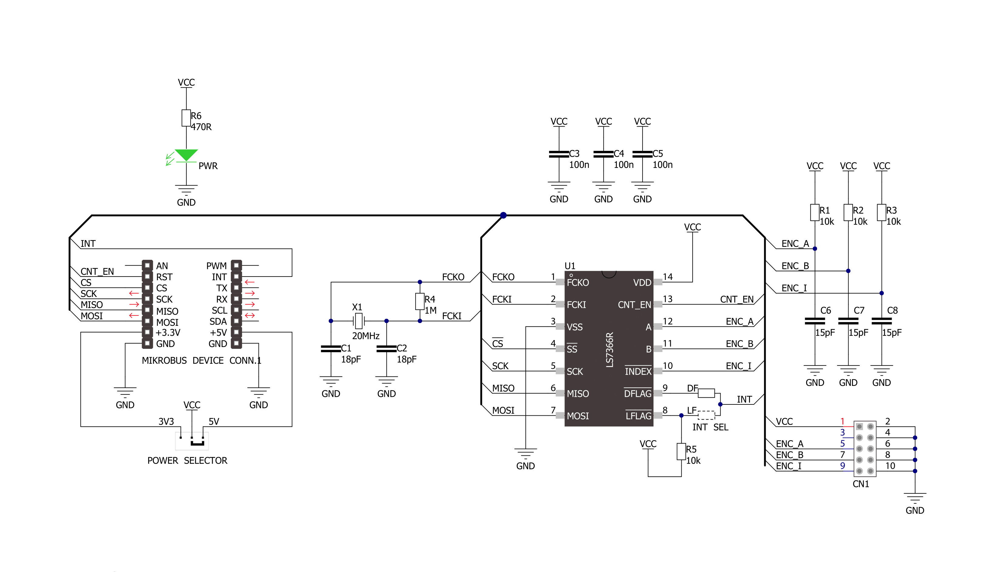
Counter Click is based on the LS7366R, a 32-bit quadrature counter with a serial interface from LSI Computer Systems. It is a CMOS counter with a direct interface for quadrature clocks from incremental encoders. It also interfaces with the index signals from incremental encoders to perform various marker functions. This counter can be configured to operate as a 1, 2, 3, or 4-byte counter. It can also be programmed to work in several counting modes such as Modulo-N, Non-recycle, Range-limit, or Free-running mode. This Click board™ features a 2x5 header (2.54mm pitch) with pins to interface the LS7366R inputs, VCC, and a few GNDs, basically the power supply
pins of the Click board™ itself. The VCC and GND pins can power the quadrature incremental encoder. This header also includes ENCA and ENCB, the input A and B pins of the LS7366R, to directly apply the quadrature clock outputs from incremental encoders on them, and Index (ENCI) pin, a programmable input driven directly by an incremental encoder's index output. The LS7366R uses a standard 4-wire SPI serial interface to communicate with the host MCU over the mikroBUS™ socket. The counter is enabled when EN input is in a high logic state; otherwise, it is disabled with a LOW logic level. In addition, this Click board™ features interrupt over INT pin that
can be configured to use LFLAG or DFLAG over the LF and DF solder jumpers with DFLAG set by default. This way, users can choose LFLAG, an open drain latched output, or DFLAG, an instantaneous push-pull output, thus using these outputs to flag Carry, Borrow, Compare, and Index occurrences. This Click board™ can operate with either 3.3V or 5V logic voltage levels selected via the PWR SEL jumper. This way, both 3.3V and 5V capable MCUs can use the communication lines properly. Also, this Click board™ comes equipped with a library containing easy-to-use functions and an example code that can be used as a reference for further development.

Features overview
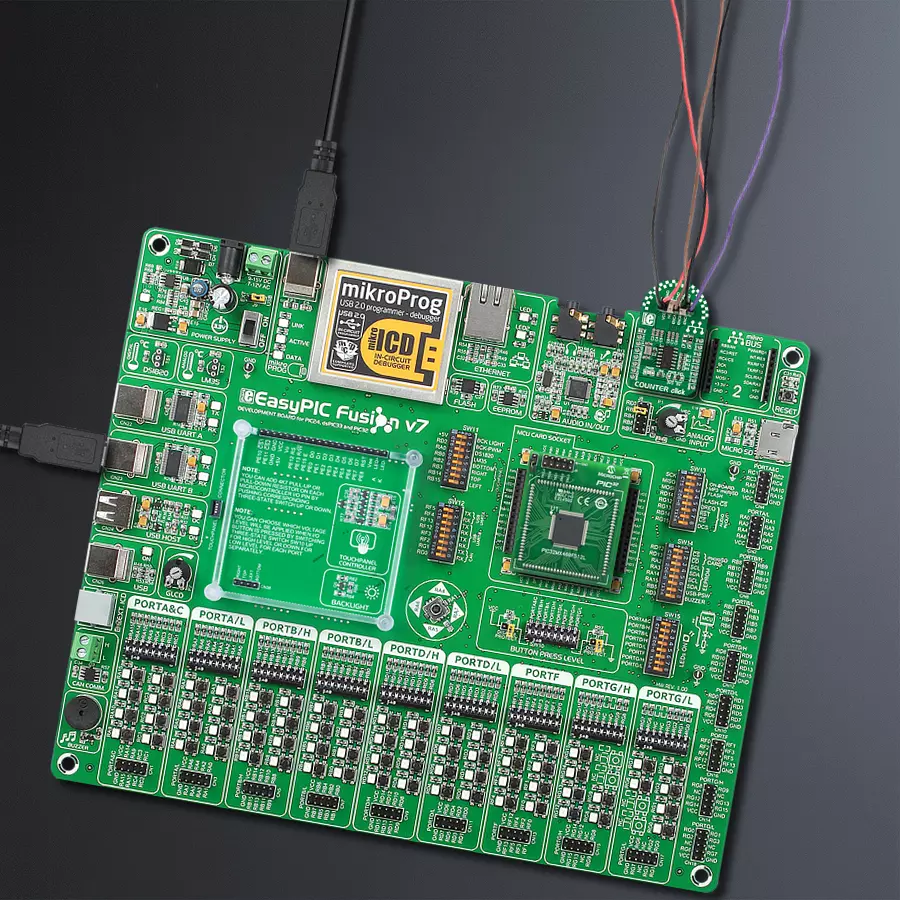
Development board
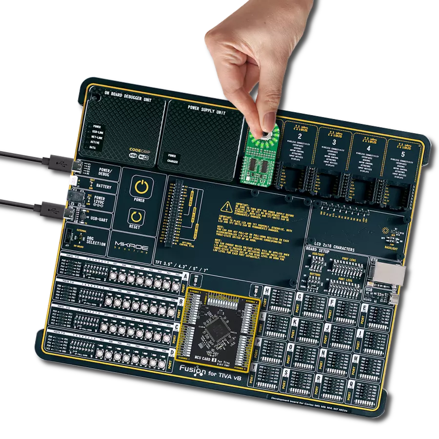
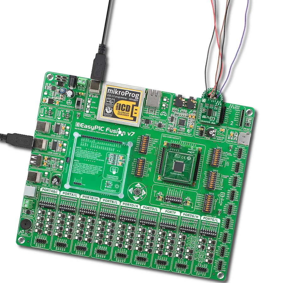
EasyPIC Fusion v7 is the seventh generation of PIC development boards specially designed to develop embedded applications rapidly. It supports a wide range of 16/32-bit PIC microcontrollers from Microchip and a broad set of unique functions, such as a powerful onboard mikroProg programmer and In-Circuit debugger over USB-B. The development board is well organized and designed so that the end-user has all the necessary elements, such as switches, buttons, indicators, connectors, and others, in one place. With two different connectors for each port, EasyPIC Fusion v7 allows you to connect accessory boards, sensors, and custom electronics more efficiently than ever. Each part of
the EasyPIC Fusion v7 development board contains the components necessary for the most efficient operation of the same board. An integrated mikroProg, a fast USB 2.0 programmer with mikroICD hardware In-Circuit Debugger, offers many valuable programming/debugging options and seamless integration with the Mikroe software environment. Besides it also includes a clean and regulated power supply block for the development board. It can use a wide range of external power sources, including an external 12V power supply, 7-12V AC or 9-15V DC via DC connector/screw terminals, and a power source via the USB Type-B (USB-B) connector. Communication options such
as USB-UART, USB-HOST, CAN, and Ethernet are also included, including the well-established mikroBUS™ standard, one display option for the TFT board line of products, and a standard TQFP socket for the seventh-generation MCU cards. This socket covers a wide range of 16-bit dsPIC/PIC24 and 32-bit PIC32 MCUs. EasyPIC Fusion v7 is an integral part of the Mikroe ecosystem for rapid development. Natively supported by Mikroe software tools, it covers many aspects of prototyping and development thanks to a considerable number of different Click boards™ (over a thousand boards), the number of which is growing every day.

Microcontroller Overview
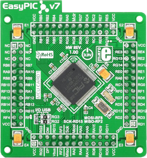
MCU Card / MCU
Type
7th Generation
Architecture
PIC32
MCU Memory (KB)
512
Silicon Vendor
Microchip
Pin count
100
RAM (Bytes)
32768
Used MCU Pins
mikroBUS™ mapper
Take a closer look
Click board™ Schematic
Step by step
Project assembly

Start by selecting your development board and Click board™. Begin with the EasyPIC Fusion v7 as your development board.


Track your results in real time
Application Output
1. Application Output - In Debug mode, the 'Application Output' window enables real-time data monitoring, offering direct insight into execution results. Ensure proper data display by configuring the environment correctly using the provided tutorial.

2. UART Terminal - Use the UART Terminal to monitor data transmission via a USB to UART converter, allowing direct communication between the Click board™ and your development system. Configure the baud rate and other serial settings according to your project's requirements to ensure proper functionality. For step-by-step setup instructions, refer to the provided tutorial.

3. Plot Output - The Plot feature offers a powerful way to visualize real-time sensor data, enabling trend analysis, debugging, and comparison of multiple data points. To set it up correctly, follow the provided tutorial, which includes a step-by-step example of using the Plot feature to display Click board™ readings. To use the Plot feature in your code, use the function: plot(*insert_graph_name*, variable_name);. This is a general format, and it is up to the user to replace 'insert_graph_name' with the actual graph name and 'variable_name' with the parameter to be displayed.

Software Support
Library Description
This library contains API for Counter Click driver.
Key functions:
counter_read_cntr- This function reads CNTR, using click object.counter_read_str- This function reads STR, using click object.counter_read_otr- This function reads OTR, using click object.
Open Source
Code example
The complete application code and a ready-to-use project are available through the NECTO Studio Package Manager for direct installation in the NECTO Studio. The application code can also be found on the MIKROE GitHub account.
/*!
 * \file
 * \brief Counter Click example
 *
 * # Description
 * This application measures the speed and the position of the DC motor shafts.
 *
 * The demo application is composed of two sections :
 *
 * ## Application Init
 * Initializes driver and configures the Click board.
 *
 * ## Application Task
 * Reads data from the CNTR register and calculates the speed of the motor in Rad/s.
 * All data is being displayed on the USB UART terminal where you can track their changes.
 * The CNTR is a software configurable 8, 16, 24 or 32-bit up/down counter which
 * counts the up/down pulses resulting from the quadrature clocks applied at the
 * A and B inputs, or alternatively, in non-quadrature mode, pulses applied at the A input.
 *
 * ## NOTE
 * An appropriate motor with optical encoder needs to be connected to the Click board.
 *
 * \author MikroE Team
 *
 */
// ------------------------------------------------------------------- INCLUDES

#include "board.h"
#include "log.h"
#include "counter.h"

// ------------------------------------------------------------------ VARIABLES

static counter_t counter;
static log_t logger;

static int32_t count;
static int32_t count_old;
static float speed;

// ------------------------------------------------------ APPLICATION FUNCTIONS

void application_init ( void )
{
    log_cfg_t log_cfg;
    counter_cfg_t cfg;

    /**
     * Logger initialization.
     * Default baud rate: 115200
     * Default log level: LOG_LEVEL_DEBUG
     * @note If USB_UART_RX and USB_UART_TX
     * are defined as HAL_PIN_NC, you will
     * need to define them manually for log to work.
     * See @b LOG_MAP_USB_UART macro definition for detailed explanation.
     */
    LOG_MAP_USB_UART( log_cfg );
    log_init( &logger, &log_cfg );
    log_info( &logger, "---- Application Init ----" );

    //  Click initialization.

    counter_cfg_setup( &cfg );
    COUNTER_MAP_MIKROBUS( cfg, MIKROBUS_1 );
    counter_init( &counter, &cfg );

    counter_default_cfg( &counter );
    Delay_ms ( 300 );
}

void application_task ( void )
{
    count = counter_read_cntr( &counter );
    log_printf( &logger, "Counter: %ld\r\n",  count );
    speed = ( float ) ( count - count_old ) / 3600.0;
    speed *= 6.283185;
    log_printf( &logger, "Speed: %.4f Rad/s\r\n",  speed );
    count_old = count;
    log_printf( &logger, "-------------------------\r\n" );
    Delay_ms ( 1000 );
}

int main ( void )
{
    /* Do not remove this line or clock might not be set correctly. */
    #ifdef PREINIT_SUPPORTED
    preinit();
    #endif

    application_init( );

    for ( ; ; )
    {
        application_task( );
    }

    return 0;
}


// ------------------------------------------------------------------------ END