Unleash your creative potential with MI9639BO-B2 and dsPIC33EP512MU810
Shine brighter with monochrome

Published Sep 15, 2023
Click board™
OLED B Click
Dev. board
EasyPIC Fusion v7
Compiler
NECTO Studio
MCU
dsPIC33EP512MU810
See how our OLED solution empowers you to push the boundaries of design, functionality, and energy efficiency, making your products stand out in the market
A
A
Hardware Overview
How does it work?
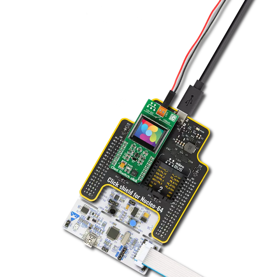
OLED B Click is based on the MI9639BO-B2, a 19.3x7.8mm 96x39px light blue monochrome passive matrix OLED display from Multi-Inno Technology. The MI9639BO-B2 display features an SSD1306, a 128x64 dot-matrix OLED/PLED segment/common driver with a controller. The controller has built-in functionalities like contrast control (256-step brightness control), normal or inverse image display, vertical and horizontal scrolling functions, and much more accessible through the I2C serial interface. OLEDs are emissive and don't require a separate backlight as LCD technology does, reducing the OLED display's overall power consumption compared to LCDs. It also does not suffer from loss of contrast due to bleed-through of the backlight in the "off" pixels. OLEDs, being emissive, have a consistent contrast ratio greater than 100:1 with no limitation in viewing angle. In addition, they don't suffer from temperature-related response time delays and
contrast changes. Like any OLED display, the MI9639BO-B2 is made from a thin film of an organic compound that emits light when exposed to a current. A small monochrome display like this represents an ideal solution for displaying text or icons. The MI9639BO-B2 display is bright, has a wide viewing angle, and has low power consumption. In addition to the display's main power supply, taken from the +3.3V microBUS™ power rail, the MI9639BO-B2 has another power pin, more precisely, the power supply for the DC/DC converter circuit. This pin is the power supply pin for the internal buffer of the DC/DC voltage converter. Therefore, for this pin, the Click board™ uses a low dropout linear regulator AP7331 from Diodes Incorporated, providing a 3.6V power supply out of 5V mikroBUS™ rail. OLED B Click communicates with MCU using the standard I2C 2-Wire interface to read data and configure settings. It allows the communication-enable
feature to be routed to the CS pin of the mikroBUS™ socket, enabling the OLED B Click for MCU communication only when the CS pin is pulled to a low logic state. In addition, it has two more pins. The first is related to the reset function, routed to the RST pin on the mikroBUS™ socket (when the pin is in a low logic state, the initialization of the chip is executed), and the second is labeled as D/C and routed to the PWM pin on the mikroBUS™ socket is I2C slave address selection pin. This Click board™ is designed to be operated only with a 3.3V logic voltage level, while 5V is used as a supply voltage of the AP7331 LDO. The board must perform appropriate logic voltage level conversion before use with MCUs with different logic levels. However, the Click board™ comes equipped with a library containing easy-to-use functions and an example code that can be used as a reference for further development.


Features overview
Development board
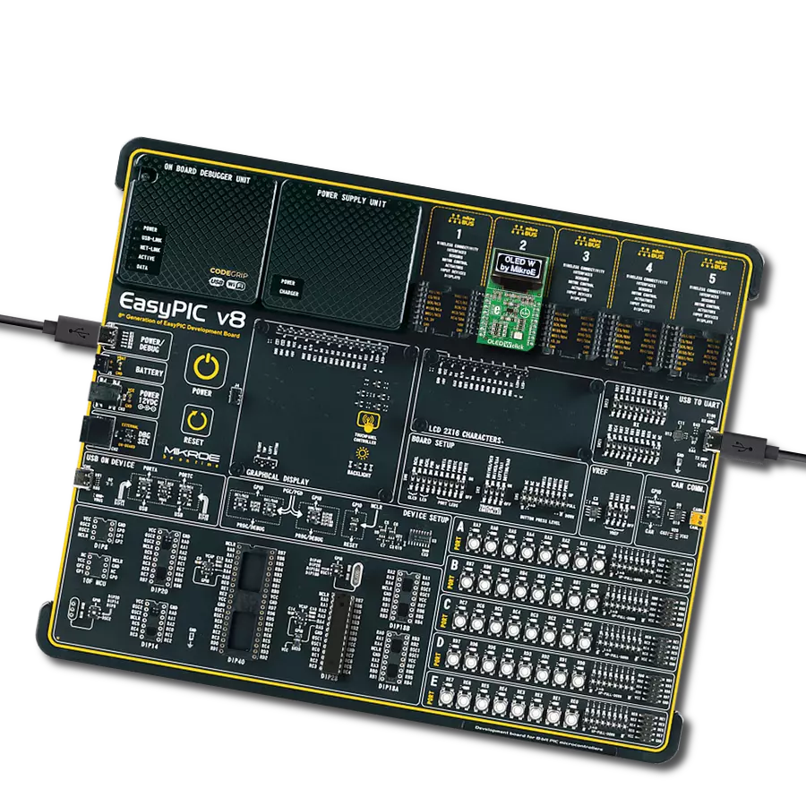
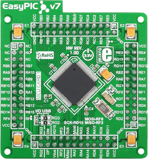
EasyPIC Fusion v7 is the seventh generation of PIC development boards specially designed to develop embedded applications rapidly. It supports a wide range of 16/32-bit PIC microcontrollers from Microchip and a broad set of unique functions, such as a powerful onboard mikroProg programmer and In-Circuit debugger over USB-B. The development board is well organized and designed so that the end-user has all the necessary elements, such as switches, buttons, indicators, connectors, and others, in one place. With two different connectors for each port, EasyPIC Fusion v7 allows you to connect accessory boards, sensors, and custom electronics more efficiently than ever. Each part of
the EasyPIC Fusion v7 development board contains the components necessary for the most efficient operation of the same board. An integrated mikroProg, a fast USB 2.0 programmer with mikroICD hardware In-Circuit Debugger, offers many valuable programming/debugging options and seamless integration with the Mikroe software environment. Besides it also includes a clean and regulated power supply block for the development board. It can use a wide range of external power sources, including an external 12V power supply, 7-12V AC or 9-15V DC via DC connector/screw terminals, and a power source via the USB Type-B (USB-B) connector. Communication options such
as USB-UART, USB-HOST, CAN, and Ethernet are also included, including the well-established mikroBUS™ standard, one display option for the TFT board line of products, and a standard TQFP socket for the seventh-generation MCU cards. This socket covers a wide range of 16-bit dsPIC/PIC24 and 32-bit PIC32 MCUs. EasyPIC Fusion v7 is an integral part of the Mikroe ecosystem for rapid development. Natively supported by Mikroe software tools, it covers many aspects of prototyping and development thanks to a considerable number of different Click boards™ (over a thousand boards), the number of which is growing every day.

Microcontroller Overview
MCU Card / MCU
Type
7th Generation
Architecture
dsPIC
MCU Memory (KB)
512
Silicon Vendor
Microchip
Pin count
100
RAM (Bytes)
53248
Used MCU Pins
mikroBUS™ mapper
Take a closer look
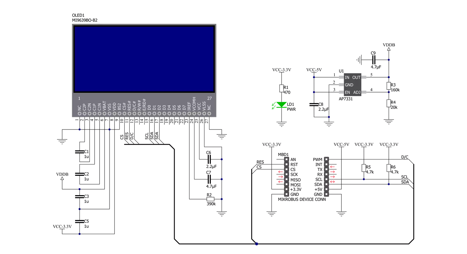
Click board™ Schematic
Step by step
Project assembly

Start by selecting your development board and Click board™. Begin with the EasyPIC Fusion v7 as your development board.


Software Support
Library Description
This library contains API for OLED B Click driver.
Key functions:
oledb_display_picture- This function allows user to display picture for on the screenoledb_clear_display- This function clears SSD1306 controller displayoledb_write_string- This function writes a text string from the selected position in a 5x7 or 6x8 font size
Open Source
Code example
The complete application code and a ready-to-use project are available through the NECTO Studio Package Manager for direct installation in the NECTO Studio. The application code can also be found on the MIKROE GitHub account.
/*!
 * @file main.c
 * @brief OLEDB Click example
 *
 # Description
 * This example demonstrates the use (control) of the OLED B display.
 *
 * The demo application is composed of two sections :
 *
 * ## Application Init
 * Configures the microcontroller for communication and initializes the Click
 * board to default state.
 *
 * ## Application Task
 * This section contains the main program that is executed showing a practical
 * example on how to use the implemented functions.
 *
 * @author MikroE Team
 *
 */

#include "board.h"
#include "log.h"
#include "oledb.h"

static oledb_t oledb;
static log_t logger;

void application_init ( void )
{
    log_cfg_t log_cfg;  /**< Logger config object. */
    oledb_cfg_t oledb_cfg;  /**< Click config object. */

    /**
     * Logger initialization.
     * Default baud rate: 115200
     * Default log level: LOG_LEVEL_DEBUG
     * @note If USB_UART_RX and USB_UART_TX
     * are defined as HAL_PIN_NC, you will
     * need to define them manually for log to work.
     * See @b LOG_MAP_USB_UART macro definition for detailed explanation.
     */
    LOG_MAP_USB_UART( log_cfg );
    log_init( &logger, &log_cfg );
    log_info( &logger, " Application Init " );

    // Click initialization.
    oledb_cfg_setup( &oledb_cfg );
    OLEDB_MAP_MIKROBUS( oledb_cfg, MIKROBUS_1 );
    err_t init_flag  = oledb_init( &oledb, &oledb_cfg );
    if ( ( I2C_MASTER_ERROR == init_flag ) || ( SPI_MASTER_ERROR == init_flag ) )
    {
        log_error( &logger, " Application Init Error. " );
        log_info( &logger, " Please, run program again... " );
        for ( ; ; );
    }

    oledb_default_cfg ( &oledb );
    log_info( &logger, " Application Task " );
}

void application_task ( void )
{
    oledb_clear_display( &oledb );
    Delay_ms ( 100 );

    oledb_write_string( &oledb, OLEDB_FONT_6X8, 0, 0, "     MIKROE     " );
    oledb_write_string( &oledb, OLEDB_FONT_6X8, 1, 0, "  OLED B Click  " );
    oledb_write_string( &oledb, OLEDB_FONT_6X8, 2, 0, "  with SSD1306  " );
    oledb_write_string( &oledb, OLEDB_FONT_6X8, 3, 0, "   controller   " );
    oledb_write_string( &oledb, OLEDB_FONT_6X8, 4, 0, "  TEST EXAMPLE  " );
    Delay_ms ( 1000 );
    Delay_ms ( 1000 );
    Delay_ms ( 1000 );

    oledb_write_string( &oledb, OLEDB_FONT_6X8, 0, 0, " TEXT SCROLL EXAMPLE " );
    oledb_write_string( &oledb, OLEDB_FONT_6X8, 4, 0, " TEXT SCROLL EXAMPLE " );
    Delay_ms ( 1000 );

    oledb_scroll_right( &oledb, 4, 0 );
    // 6 seconds delay
    Delay_ms ( 1000 );
    Delay_ms ( 1000 );
    Delay_ms ( 1000 );
    Delay_ms ( 1000 );
    Delay_ms ( 1000 );
    Delay_ms ( 1000 );
    oledb_stop_scroll( &oledb );

    oledb_clear_display( &oledb );
    Delay_ms ( 100 );

    oledb_display_picture( &oledb, oledb_img_mikroe );
    Delay_ms ( 500 );
    oledb_send_cmd( &oledb, OLEDB_INVERTDISPLAY );
    Delay_ms ( 500 );
    oledb_send_cmd( &oledb, OLEDB_NORMALDISPLAY );
    Delay_ms ( 500 );
    oledb_send_cmd( &oledb, OLEDB_INVERTDISPLAY );
    Delay_ms ( 500 );
    oledb_send_cmd( &oledb, OLEDB_NORMALDISPLAY );
    Delay_ms ( 300 );

    for ( uint8_t contrast = 0xAF; contrast > 0x00; contrast-- )
    {
        oledb_set_contrast( &oledb, contrast );
        Delay_ms ( 5 );
    }

    for ( uint8_t contrast = 0x00; contrast < 0xAF; contrast++ )
    {
        oledb_set_contrast( &oledb, contrast );
        Delay_ms ( 5 );
    }

    oledb_scroll_left( &oledb, 0, 4 );
    Delay_ms ( 1000 );
    oledb_stop_scroll( &oledb );

    oledb_scroll_right( &oledb, 0, 4 );
    Delay_ms ( 1000 );
    Delay_ms ( 1000 );
    oledb_stop_scroll( &oledb );

    oledb_scroll_left( &oledb, 0, 4 );
    Delay_ms ( 1000 );
    oledb_stop_scroll( &oledb );
}

int main ( void )
{
    /* Do not remove this line or clock might not be set correctly. */
    #ifdef PREINIT_SUPPORTED
    preinit();
    #endif

    application_init( );

    for ( ; ; )
    {
        application_task( );
    }

    return 0;
}

// ------------------------------------------------------------------------ END
Additional Support
Resources
Category:OLED