Measure tilt on both the X and Y axes with exceptional accuracy using the SCL3400-D01 and EasyMx PRO v7 for Tiva MCU card with TM4C123GH6PMI
Digital 2-axis inclinometer based on capacitive 3D-MEMS technology

Published May 27, 2024
Click board™
Inclinometer 3 Click
Dev. board
EasyMx PRO v7 for Tiva
Compiler
NECTO Studio
MCU
TM4C123GH6PMI
Provide high-precision tilt and leveling measurement capabilities for various applications requiring accurate angular orientation sensing
A
A
Hardware Overview
How does it work?
Inclinometer 3 Click is based on the SCL3400-D01, a high-performance, two-axis (XY) inclinometer sensor from Murata, employing their advanced capacitive 3D-MEMS technology for precise tilt sensing. This sensor integrates a sophisticated mixed-signal ASIC that provides signal processing through a flexible SPI digital interface, enhancing its functionality and ease of integration. Housed in a durable 12-pin pre-molded plastic casing, the SCL3400-D01 ensures consistent performance and reliability across its operational lifespan. This sensor is meticulously designed, manufactured, and tested to meet rigorous stability, reliability, and quality standards, making it exceptionally dependable across various temperatures and vibrations. Additionally, it incorporates several
advanced self-diagnostic features that further bolster its operational integrity. Idealfor applications requiring unmatched stability and accuracy in challenging environments, the SCL3400-D01 stands out with its selectable measurement modes of ±30° with a 10Hz Low Pass Filter (LPF) and ±90° with a 40Hz LPF, providing flexible deployment options. It has an ultra-low noise density and a high resolution of up to 32768LSB/g, ensuring precise and clear signal outputs under various conditions. Typical uses of this inclinometer solution include leveling, tilt sensing, structural health monitoring, and more complex applications such as inertial measurement units (IMUs) and positioning and guidance systems, where precise movement and position tracking are crucial. As mentioned, the
Inclinometer 3 Click Click communicates with the host MCU through a standard 4-wire SPI, capable of up to 10MHz operational frequency (2MHz is the typical frequency). Although the SCL3400-D01 is designed to operate only at 3.3V, this Click board™ also includes a TXB0106 logic level translator, which ensures the operation of this Click board™ with both 3.3V and 5V capable MCUs. This Click board™ can operate with either 3.3V or 5V logic voltage levels selected via the VIO SEL jumper. This way, both 3.3V and 5V capable MCUs can use the communication lines properly. Also, this Click board™ comes equipped with a library containing easy-to-use functions and an example code that can be used as a reference for further development.

Features overview
Development board
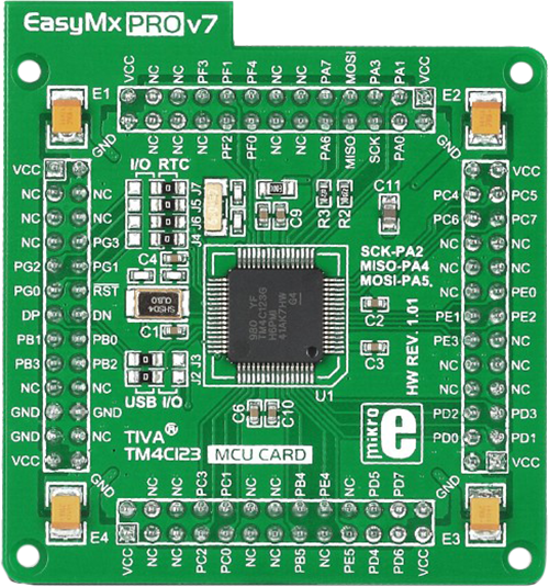
EasyMx PRO v7 for TIVA is the seventh generation of ARM development boards specially designed for the needs of rapid development of embedded applications. It supports a wide range of 32-bit ARM microcontrollers from Texas Instruments and a broad set of unique functions, such as a powerful onboard mikroProg programmer and In-Circuit debugger over USB-B. The development board is well organized and designed so that the end-user has all the necessary elements, such as switches, buttons, indicators, connectors, and others, in one place. With two different connectors for each port, EasyMx PRO v7 for TIVA allows you to connect accessory boards, sensors, and custom electronics more efficiently than ever. Each part of the EasyMx
PRO v7 for TIVA development board contains the components necessary for the most efficient operation of the same board. An integrated mikroProg, a fast USB 2.0 programmer with mikroICD hardware In-Circuit Debugger, offers many valuable programming/debugging options and seamless integration with the Mikroe software environment. Besides it also includes a clean and regulated power supply block for the development board. It can use a wide range of external power sources, including an external 12V power supply, 7-23V AC or 9-32V DC via DC connector/screw terminals, and a power source via the USB Type-B (USB-B) connector. Communication options such as USB-UART, USB-HOST/DEVICE, CAN, and
Ethernet are also included, including the well-established mikroBUS™ standard, one display option for the TFT board line of products, and a standard TQFP socket for the seventh-generation MCU cards. This socket covers a wide range of 32-bit TIVA-series ARM Cortex-M4 MCUs. EasyMx PRO v7 for TIVA is an integral part of the Mikroe ecosystem for rapid development. Natively supported by Mikroe software tools, it covers many aspects of prototyping and development thanks to a considerable number of different Click boards™ (over a thousand boards), the number of which is growing every day.

Microcontroller Overview
MCU Card / MCU
Type
7th Generation
Architecture
ARM Cortex-M4
MCU Memory (KB)
256
Silicon Vendor
Texas Instruments
Pin count
64
RAM (Bytes)
32k
Used MCU Pins
mikroBUS™ mapper
Take a closer look
Click board™ Schematic

Step by step
Project assembly

Start by selecting your development board and Click board™. Begin with the EasyMx PRO v7 for Tiva as your development board.


Software Support
Library Description
This library contains API for Inclinometer 3 Click driver.
Key functions:
inclinometer3_get_axes- This function reads the accelerometer sensor axes data by using SPI serial interface.inclinometer3_get_temperature- This function reads the temperature measurement data by using SPI serial interface.
Open Source
Code example
The complete application code and a ready-to-use project are available through the NECTO Studio Package Manager for direct installation in the NECTO Studio. The application code can also be found on the MIKROE GitHub account.
/*!
 * @file main.c
 * @brief Inclinometer 3 Click example
 *
 * # Description
 * This library contains API for the Inclinometer 3 Click driver.
 * The library initializes and defines the SPI drivers to
 * write and read data from registers, as well as the default configuration
 * for the reading accelerator and temperature data.
 *
 * The demo application is composed of two sections :
 *
 * ## Application Init
 * The initialization of the SPI module, log UART, and additional pins.
 * After the driver init, the app executes a default configuration.
 *
 * ## Application Task
 * This example demonstrates the use of the Inclinometer 3 Click board.
 * Measures and displays acceleration data for the XY-axis [mg]
 * and temperature [degree Celsius] data.
 * Results are being sent to the UART Terminal, where you can track their changes.
 *
 * @author Nenad Filipovic
 *
 */

#include "board.h"
#include "log.h"
#include "inclinometer3.h"

static inclinometer3_t inclinometer3;
static log_t logger;

void application_init ( void )
{
    log_cfg_t log_cfg;  /**< Logger config object. */
    inclinometer3_cfg_t inclinometer3_cfg;  /**< Click config object. */

    /**
     * Logger initialization.
     * Default baud rate: 115200
     * Default log level: LOG_LEVEL_DEBUG
     * @note If USB_UART_RX and USB_UART_TX
     * are defined as HAL_PIN_NC, you will
     * need to define them manually for log to work.
     * See @b LOG_MAP_USB_UART macro definition for detailed explanation.
     */
    LOG_MAP_USB_UART( log_cfg );
    log_init( &logger, &log_cfg );
    log_info( &logger, " Application Init " );

    // Click initialization.
    inclinometer3_cfg_setup( &inclinometer3_cfg );
    INCLINOMETER3_MAP_MIKROBUS( inclinometer3_cfg, MIKROBUS_1 );
    if ( SPI_MASTER_ERROR == inclinometer3_init( &inclinometer3, &inclinometer3_cfg ) )
    {
        log_error( &logger, " Communication init." );
        for ( ; ; );
    }

    if ( INCLINOMETER3_ERROR == inclinometer3_default_cfg ( &inclinometer3 ) )
    {
        log_error( &logger, " Default configuration." );
        for ( ; ; );
    }

    log_info( &logger, " Application Task " );
    log_printf( &logger, " ________________________ \r\n" );
}

void application_task ( void )
{
    float temperature = 0, x_axes = 0, y_axes = 0;
    if ( ( INCLINOMETER3_OK == inclinometer3_get_temperature( &inclinometer3, &temperature ) ) &&
         ( INCLINOMETER3_OK == inclinometer3_get_axes( &inclinometer3, &x_axes, &y_axes ) ) )
    {
        log_printf( &logger, " Accel X: %.2f mg\r\n", x_axes );
        log_printf( &logger, " Accel Y: %.2f mg\r\n\r\n", y_axes );
        log_printf( &logger, " Temperature : %.2f degC\r\n", temperature );
        log_printf( &logger, " ________________________ \r\n" );
        Delay_ms ( 1000 );
    }
}

int main ( void )
{
    /* Do not remove this line or clock might not be set correctly. */
    #ifdef PREINIT_SUPPORTED
    preinit();
    #endif

    application_init( );

    for ( ; ; )
    {
        application_task( );
    }

    return 0;
}

// ------------------------------------------------------------------------ END
Additional Support
Resources
Category:Motion


