Maintain your battery in prime condition with LTC3337 and STM32L496AG
Keep tabs on your batteries anytime, anywhere!
Published Jul 22, 2025
Click board™
BATT-MON 4 Click
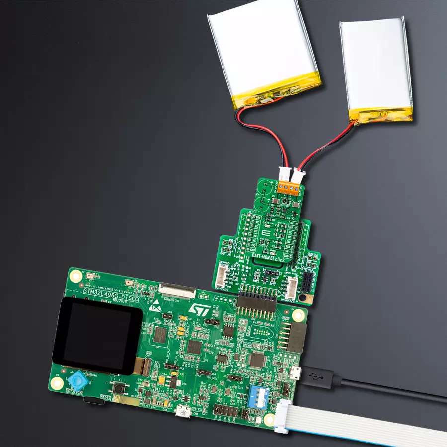
Dev. board
Discovery kit with STM32L496AG MCU
Compiler
NECTO Studio
MCU
STM32L496AG
Upgrade your solution with advanced battery diagnostics technology - predict end-of-service or early battery failure and stay ahead of potential issues
A
A
Hardware Overview
How does it work?
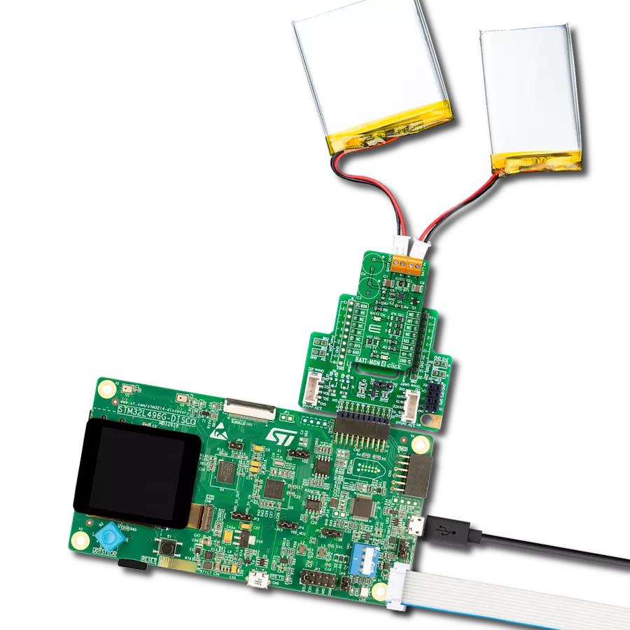
BATT-MON 4 Click is based on the LTC3337, a primary battery state of health monitor from Analog Devices, designed to be placed in series with a primary battery with minimal associated series voltage drop. The LTC3337 integrates a precision coulomb counter that monitors the accumulated charge transferred from a primary battery connected to its BATT IN terminal to an output load connected to its BATT OUT terminal. The patented infinite dynamic range coulomb counter tallies all accumulated battery discharge and stores it in an internal register accessible via an I2C interface. This Click board™ communicates with MCU using the standard I2C 2-Wire interface to read data and configure settings, supporting Standard Mode operation with a clock frequency of 100kHz and Fast Mode up to 400kHz. The LTC3337 also integrates additional state of health monitoring, which measures and reports through the I2C interface, such as battery voltage, battery impedance, and temperature, to quantify the battery's charge state and health. In addition, it also has a programmable discharge alarm threshold based on this state of charge (SOC).
When the threshold is reached, an interrupt is generated at the INT pin of the mikroBUS™ socket. An integrated coulomb counter operates with a configurable peak current limit. The LTC3337 supports input voltages from 1.8V to 5.5V and a peak current of up to 100mA; more precisely, the peak input current limit is selectable from 5mA to 100mA. The selection can be made by positioning SMD jumpers labeled IPK SEL to an appropriate position of 0 or 1. Coulombs can be calculated for either the BATT IN or BATT OUT terminal, determined by the selected position of the AVCC SEL jumper. The AVCC SEL is the power supply for all internal LTC3337 circuits and can be connected to the BATT IN or OUT terminal. With AVCC connected to BATT OUT, the coulomb counter counts all coulombs coming out of the battery, including those associated with the LTC3337's quiescent current, which effectively parallels the output load at BATT OUT. When connecting AVCC to BATT IN, the LTC3337's quiescent current represents an error on coulombs out of the battery. However, coulombs associated purely with the output load are now more accurately counted,
which may benefit output power metering applications. BATT-MON 4 Click also possesses one green LED indicator labeled as BATT OK used as a battery status indicator, alongside the option of utilizing a stack of two supercapacitors, C4 and C3, an integrated ±10mA supercapacitor balancer available to balance a stack of two supercapacitors at the BATT OUT terminal. This option is turned off by default with capacitors C4 and C3 unpopulated and resistor R5 populated. To activate this feature, remove the R5 resistor and populate C4 and C3 capacitors (an example of capacitors used on this board is SCCR20B335PRB). This Click board™ can operate with either 3.3V or 5V logic voltage levels selected via the VIO SEL jumper. This way, both 3.3V and 5V capable MCUs can use the communication lines properly. However, the Click board™ comes equipped with a library containing easy-to-use functions and an example code that can be used, as a reference, for further development.

Features overview
Development board
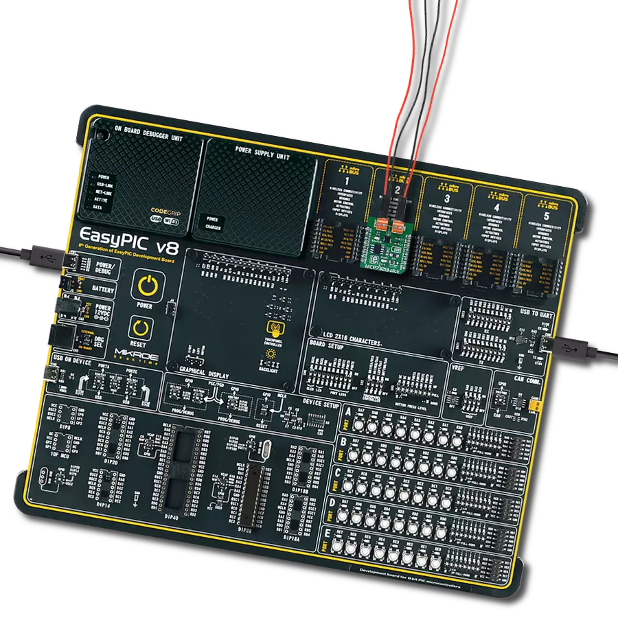
The 32L496GDISCOVERY Discovery kit serves as a comprehensive demonstration and development platform for the STM32L496AG microcontroller, featuring an Arm® Cortex®-M4 core. Designed for applications that demand a balance of high performance, advanced graphics, and ultra-low power consumption, this kit enables seamless prototyping for a wide range of embedded solutions. With its innovative energy-efficient
architecture, the STM32L496AG integrates extended RAM and the Chrom-ART Accelerator, enhancing graphics performance while maintaining low power consumption. This makes the kit particularly well-suited for applications involving audio processing, graphical user interfaces, and real-time data acquisition, where energy efficiency is a key requirement. For ease of development, the board includes an onboard ST-LINK/V2-1
debugger/programmer, providing a seamless out-of-the-box experience for loading, debugging, and testing applications without requiring additional hardware. The combination of low power features, enhanced memory capabilities, and built-in debugging tools makes the 32L496GDISCOVERY kit an ideal choice for prototyping advanced embedded systems with state-of-the-art energy efficiency.

Microcontroller Overview
MCU Card / MCU

Architecture
ARM Cortex-M4
MCU Memory (KB)
1024
Silicon Vendor
STMicroelectronics
Pin count
169
RAM (Bytes)
327680
You complete me!
Accessories
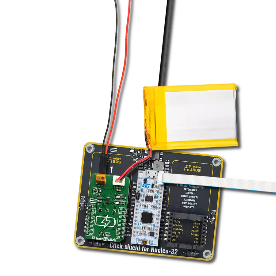
Li-Polymer Battery is the ideal solution for devices that demand a dependable and long-lasting power supply while emphasizing mobility. Its compatibility with mikromedia boards ensures easy integration without additional modifications. With a voltage output of 3.7V, the battery meets the standard requirements of many electronic devices. Additionally, boasting a capacity of 2000mAh, it can store a substantial amount of energy, providing sustained power for extended periods. This feature minimizes the need for frequent recharging or replacement. Overall, the Li-Polymer Battery is a reliable and autonomous power source, ideally suited for devices requiring a stable and enduring energy solution. You can find a more extensive choice of Li-Polymer batteries in our offer.

Used MCU Pins
mikroBUS™ mapper
Take a closer look
Click board™ Schematic

Step by step
Project assembly

Start by selecting your development board and Click board™. Begin with the Discovery kit with STM32L496AG MCU as your development board.


Track your results in real time
Application Output
1. Application Output - In Debug mode, the 'Application Output' window enables real-time data monitoring, offering direct insight into execution results. Ensure proper data display by configuring the environment correctly using the provided tutorial.

2. UART Terminal - Use the UART Terminal to monitor data transmission via a USB to UART converter, allowing direct communication between the Click board™ and your development system. Configure the baud rate and other serial settings according to your project's requirements to ensure proper functionality. For step-by-step setup instructions, refer to the provided tutorial.

3. Plot Output - The Plot feature offers a powerful way to visualize real-time sensor data, enabling trend analysis, debugging, and comparison of multiple data points. To set it up correctly, follow the provided tutorial, which includes a step-by-step example of using the Plot feature to display Click board™ readings. To use the Plot feature in your code, use the function: plot(*insert_graph_name*, variable_name);. This is a general format, and it is up to the user to replace 'insert_graph_name' with the actual graph name and 'variable_name' with the parameter to be displayed.

Software Support
Library Description
This library contains API for BATT-MON 4 Click driver.
Key functions:
battmon4_get_die_temperatureThis function reads the chip DIE temperature in Celsius.battmon4_get_batt_in_voltageThis function reads the voltage from BATT IN when Ipeak is ON and OFF.battmon4_get_batt_out_voltageThis function reads the voltage from BATT OUT when Ipeak is ON and OFF.
Open Source
Code example
The complete application code and a ready-to-use project are available through the NECTO Studio Package Manager for direct installation in the NECTO Studio. The application code can also be found on the MIKROE GitHub account.
/*!
 * @file main.c
 * @brief BATTMON4 Click example
 *
 * # Description
 * This example demonstrates the use of BATT-MON 4 Click board by reading
 * the battery voltage and the chip internal temperature.
 *
 * The demo application is composed of two sections :
 *
 * ## Application Init
 * Initializes the driver and logger.
 *
 * ## Application Task
 * Reads the chip DIE temperature and voltage from BATT IN and BATT OUT and displays
 * the results on the USB UART approximately once per second.
 *
 * @author Stefan Filipovic
 *
 */

#include "board.h"
#include "log.h"
#include "battmon4.h"

static battmon4_t battmon4;
static log_t logger;

void application_init ( void )
{
    log_cfg_t log_cfg;  /**< Logger config object. */
    battmon4_cfg_t battmon4_cfg;  /**< Click config object. */

    /**
     * Logger initialization.
     * Default baud rate: 115200
     * Default log level: LOG_LEVEL_DEBUG
     * @note If USB_UART_RX and USB_UART_TX
     * are defined as HAL_PIN_NC, you will
     * need to define them manually for log to work.
     * See @b LOG_MAP_USB_UART macro definition for detailed explanation.
     */
    LOG_MAP_USB_UART( log_cfg );
    log_init( &logger, &log_cfg );
    log_info( &logger, " Application Init " );

    // Click initialization.
    battmon4_cfg_setup( &battmon4_cfg );
    BATTMON4_MAP_MIKROBUS( battmon4_cfg, MIKROBUS_1 );
    if ( I2C_MASTER_ERROR == battmon4_init( &battmon4, &battmon4_cfg ) )
    {
        log_error( &logger, " Communication init." );
        for ( ; ; );
    }

    log_info( &logger, " Application Task " );
}

void application_task ( void )
{
    float die_temperature, batt_in_v_ipeak_on, batt_in_v_ipeak_off, batt_out_v_ipeak_on, batt_out_v_ipeak_off;

    if ( BATTMON4_OK == battmon4_get_die_temperature ( &battmon4, &die_temperature ) )
    {
        log_printf ( &logger, " Die Temperature: %.2f C \r\n\n", die_temperature );
    }

    if ( BATTMON4_OK == battmon4_get_batt_in_voltage ( &battmon4, &batt_in_v_ipeak_on, &batt_in_v_ipeak_off ) )
    {
        log_printf ( &logger, " BATT IN \r\n Ipeak ON: %.1f mV \r\n Ipeak OFF: %.1f mV \r\n\n",
                     batt_in_v_ipeak_on, batt_in_v_ipeak_off );
    }

    if ( BATTMON4_OK == battmon4_get_batt_out_voltage ( &battmon4, &batt_out_v_ipeak_on, &batt_out_v_ipeak_off ) )
    {
        log_printf ( &logger, " BATT OUT \r\n Ipeak ON: %.1f mV \r\n Ipeak OFF: %.1f mV \r\n\n",
                     batt_out_v_ipeak_on, batt_out_v_ipeak_off );
    }

    Delay_ms ( 1000 );
}

int main ( void )
{
    /* Do not remove this line or clock might not be set correctly. */
    #ifdef PREINIT_SUPPORTED
    preinit();
    #endif

    application_init( );

    for ( ; ; )
    {
        application_task( );
    }

    return 0;
}

// ------------------------------------------------------------------------ END
Additional Support
Resources
Category:Battery charger