Experience precise and reliable motion sensing with ADXL367 and STM32F746ZG
Get ready to rumble!
Published Apr 07, 2023
Click board™
Accel 22 Click
Dev. board
UNI-DS v8
Compiler
NECTO Studio
MCU
STM32F746ZG
A tiny yet mighty accelerometer that's turning the world of motion sensing on its head!
A
A
Hardware Overview
How does it work?
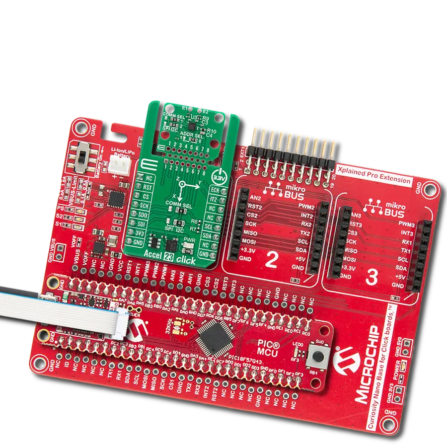
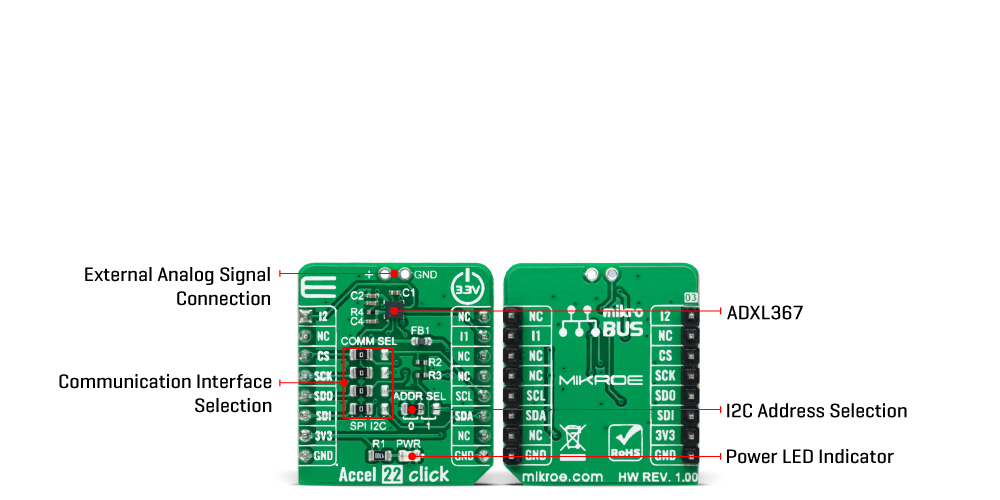
Accel 22 Click is based on the ADXL367, a complete 3-axis acceleration measurement system from Analog Devices that operate at low power consumption levels. It consists of an ADC for synchronous conversion of an input from a third sensor and one internal temperature sensor. It measures both dynamic accelerations, resulting from motion or shock, and static acceleration, such as tilt, and allows selectable full-scale acceleration measurements in ranges of ±2g, ±4g, and ±8g with a resolution of 0.25mg/LSB on the ±2g range. Acceleration is reported digitally, communicating via the SPI or the I2C protocol and providing 14-bit output resolution. The ADXL367 has three operating modes: Measurement mode for continuous wide-bandwidth sensing, Wake-up mode for limited bandwidth activity detection, and Standby mode for power conservation. Measurement mode represents its normal operating mode, and in this mode, acceleration data is read continuously, while the Wake-Up mode is ideal for simple detection of the presence or absence of motion at low power consumption.
Wake-up mode helps implement a motion-activated ON/OFF switch, allowing the rest of the system to Power-Down until the activity is detected. In addition, the Standby mode suspends measurement and reduces power consumption. Accel 22 Click allows using both I2C and SPI interfaces. The selection can be made by positioning SMD jumpers labeled as COMM SEL in an appropriate position. Note that all the jumpers' positions must be on the same side, or the Click board™ may become unresponsive. While the I2C interface is selected, the ADXL367 allows choosing the least significant bit (LSB) of its I2C slave address using the SMD jumper labeled ADDR SEL. This Click board™ also possesses two register-configurated interrupt pins, I1 and I2, routed to the INT and AN pins on the mikroBUS™, which has a dual function that can trigger interrupts to alert the host of certain status conditions. They can be used as classic interrupt pins to signal MCU that an event has been sensed or can be used, e.g., I1 as an input for external clocking and I2 as input for synchronized sampling.
One or both of these alternate functions can be used concurrently; however, if an interrupt pin is used for its alternate function, it cannot simultaneously be used for its primary function, to signal interrupts. The ADXL367 incorporates a 14-bit analog-to-digital converter (ADC) to digitize the external analog signal, connected to a header at the top of the board, which is unpopulated by default. The ADC converts analog inputs ranging from 10% to 90% of the internally regulated voltage, limiting the external ADC's input range to a maximum of 1V. This Click board™ can only be operated with a 3.3V logic voltage level. The board must perform appropriate logic voltage level conversion before using MCUs with different logic levels. However, the Click board™ comes equipped with a library containing functions and an example code that can be used as a reference for further development.
Features overview
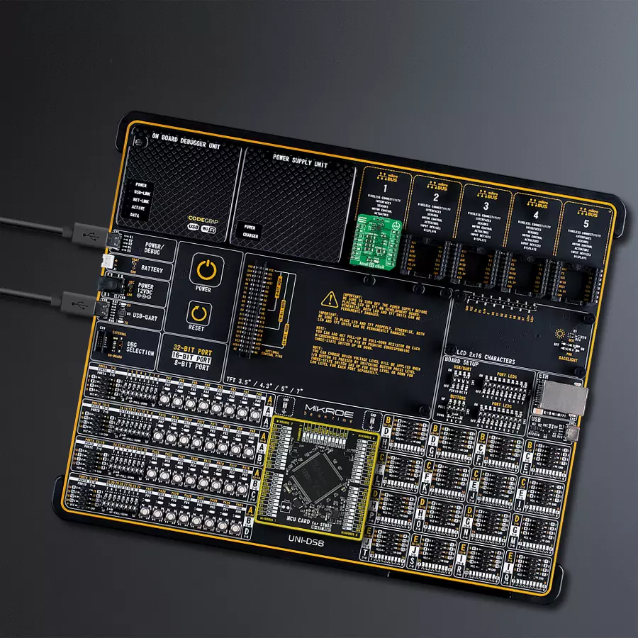
Development board
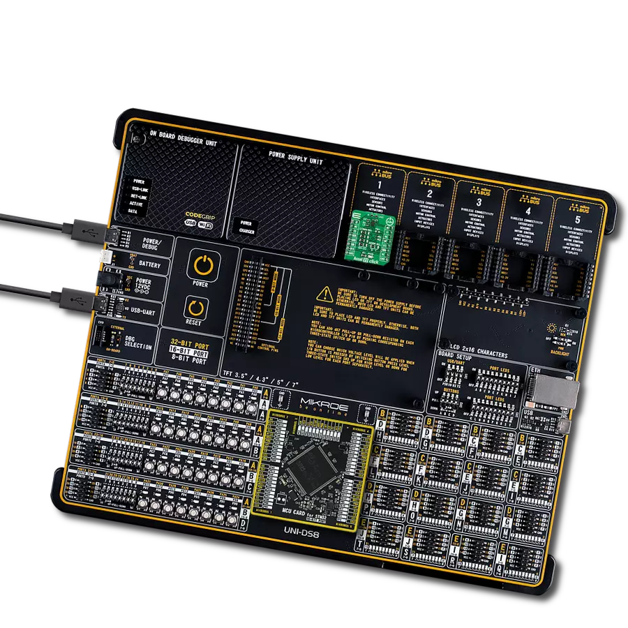
UNI-DS v8 is a development board specially designed for the needs of rapid development of embedded applications. It supports a wide range of microcontrollers, such as different STM32, Kinetis, TIVA, CEC, MSP, PIC, dsPIC, PIC32, and AVR MCUs regardless of their number of pins, and a broad set of unique functions, such as the first-ever embedded debugger/programmer over WiFi. The development board is well organized and designed so that the end-user has all the necessary elements, such as switches, buttons, indicators, connectors, and others, in one place. Thanks to innovative manufacturing technology, UNI-DS v8 provides a fluid and immersive working experience, allowing access anywhere and under any
circumstances at any time. Each part of the UNI-DS v8 development board contains the components necessary for the most efficient operation of the same board. An advanced integrated CODEGRIP programmer/debugger module offers many valuable programming/debugging options, including support for JTAG, SWD, and SWO Trace (Single Wire Output)), and seamless integration with the Mikroe software environment. Besides, it also includes a clean and regulated power supply module for the development board. It can use a wide range of external power sources, including a battery, an external 12V power supply, and a power source via the USB Type-C (USB-C) connector. Communication options such as USB-UART, USB
HOST/DEVICE, CAN (on the MCU card, if supported), and Ethernet is also included. In addition, it also has the well-established mikroBUS™ standard, a standardized socket for the MCU card (SiBRAIN standard), and two display options for the TFT board line of products and character-based LCD. UNI-DS v8 is an integral part of the Mikroe ecosystem for rapid development. Natively supported by Mikroe software tools, it covers many aspects of prototyping and development thanks to a considerable number of different Click boards™ (over a thousand boards), the number of which is growing every day.

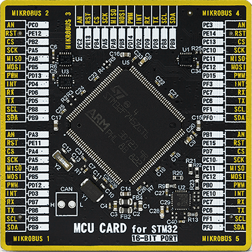
Microcontroller Overview
MCU Card / MCU
Type
8th Generation
Architecture
ARM Cortex-M7
MCU Memory (KB)
1024
Silicon Vendor
STMicroelectronics
Pin count
144
RAM (Bytes)
327680
Used MCU Pins
mikroBUS™ mapper
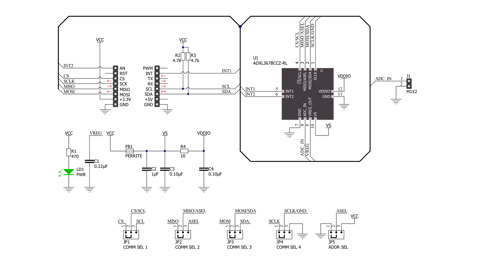
Take a closer look
Click board™ Schematic
Step by step
Project assembly

Start by selecting your development board and Click board™. Begin with the UNI-DS v8 as your development board.


Track your results in real time
Application Output
1. Application Output - In Debug mode, the 'Application Output' window enables real-time data monitoring, offering direct insight into execution results. Ensure proper data display by configuring the environment correctly using the provided tutorial.

2. UART Terminal - Use the UART Terminal to monitor data transmission via a USB to UART converter, allowing direct communication between the Click board™ and your development system. Configure the baud rate and other serial settings according to your project's requirements to ensure proper functionality. For step-by-step setup instructions, refer to the provided tutorial.

3. Plot Output - The Plot feature offers a powerful way to visualize real-time sensor data, enabling trend analysis, debugging, and comparison of multiple data points. To set it up correctly, follow the provided tutorial, which includes a step-by-step example of using the Plot feature to display Click board™ readings. To use the Plot feature in your code, use the function: plot(*insert_graph_name*, variable_name);. This is a general format, and it is up to the user to replace 'insert_graph_name' with the actual graph name and 'variable_name' with the parameter to be displayed.

Software Support
Library Description
This library contains API for Accel 22 Click driver.
Key functions:
accel22_get_axesThis function reads accel X, Y, and Z axis data in mg.accel22_get_temperatureThis function reads the temperature in Celsius.accel22_get_adcThis function reads the ADC voltage.
Open Source
Code example
The complete application code and a ready-to-use project are available through the NECTO Studio Package Manager for direct installation in the NECTO Studio. The application code can also be found on the MIKROE GitHub account.
/*!
 * @file main.c
 * @brief Accel22 Click example
 *
 * # Description
 * This example demonstrates the use of Accel 22 Click board by reading and displaying
 * Accel data (X, Y, and Z axis) as well as temperature and ADC measurements on the USB UART.
 *
 * The demo application is composed of two sections :
 *
 * ## Application Init
 * Initializes the driver and performs the Click default configuration.
 *
 * ## Application Task
 * Reads and displays the Accel data (X, Y, and Z axis) as well as temperature and ADC measurements
 * on the USB UART every 100ms approximately.
 *
 * @author Stefan Filipovic
 *
 */

#include "board.h"
#include "log.h"
#include "accel22.h"

static accel22_t accel22;
static log_t logger;

void application_init ( void )
{
    log_cfg_t log_cfg;  /**< Logger config object. */
    accel22_cfg_t accel22_cfg;  /**< Click config object. */

    /**
     * Logger initialization.
     * Default baud rate: 115200
     * Default log level: LOG_LEVEL_DEBUG
     * @note If USB_UART_RX and USB_UART_TX
     * are defined as HAL_PIN_NC, you will
     * need to define them manually for log to work.
     * See @b LOG_MAP_USB_UART macro definition for detailed explanation.
     */
    LOG_MAP_USB_UART( log_cfg );
    log_init( &logger, &log_cfg );
    log_info( &logger, " Application Init " );

    // Click initialization.
    accel22_cfg_setup( &accel22_cfg );
    ACCEL22_MAP_MIKROBUS( accel22_cfg, MIKROBUS_1 );
    err_t init_flag  = accel22_init( &accel22, &accel22_cfg );
    if ( ( I2C_MASTER_ERROR == init_flag ) || ( SPI_MASTER_ERROR == init_flag ) )
    {
        log_error( &logger, " Communication init." );
        for ( ; ; );
    }

    if ( ACCEL22_ERROR == accel22_default_cfg ( &accel22 ) )
    {
        log_error( &logger, " Default configuration." );
        for ( ; ; );
    }

    log_info( &logger, " Application Task " );
}

void application_task ( void )
{
    accel22_axes_t axes;
    // Wait for data ready indication
    while ( !accel22_get_int1_pin ( &accel22 ) );
    if ( ACCEL22_OK == accel22_get_axes ( &accel22, &axes ) )
    {
        log_printf( &logger, " X: %.2f mg\r\n", axes.x );
        log_printf( &logger, " Y: %.2f mg\r\n", axes.y );
        log_printf( &logger, " Z: %.2f mg\r\n", axes.z );
    }

    if ( ACCEL22_OK == accel22_enable_temperature_measurement ( &accel22 ) )
    {
        float temperature = 0;
        // Wait for data ready indication
        while ( !accel22_get_int1_pin ( &accel22 ) );
        if ( ACCEL22_OK == accel22_get_temperature ( &accel22, &temperature ) )
        {
            log_printf( &logger, " Temperature: %.2f C\r\n", temperature );
        }
    }

    if ( ACCEL22_OK == accel22_enable_adc_measurement ( &accel22 ) )
    {
        float adc_voltage = 0;
        // Wait for data ready indication
        while ( !accel22_get_int1_pin ( &accel22 ) );
        if ( ACCEL22_OK == accel22_get_adc ( &accel22, &adc_voltage ) )
        {
            log_printf( &logger, " ADC: %.2f V\r\n\n", adc_voltage );
        }
    }
    Delay_ms ( 100 );
}

int main ( void )
{
    /* Do not remove this line or clock might not be set correctly. */
    #ifdef PREINIT_SUPPORTED
    preinit();
    #endif

    application_init( );

    for ( ; ; )
    {
        application_task( );
    }

    return 0;
}

// ------------------------------------------------------------------------ END