Measure air pressure quickly using ICP-20100 and STM32F439ZG
Keeping the air in check

Published Mar 07, 2023
Click board™
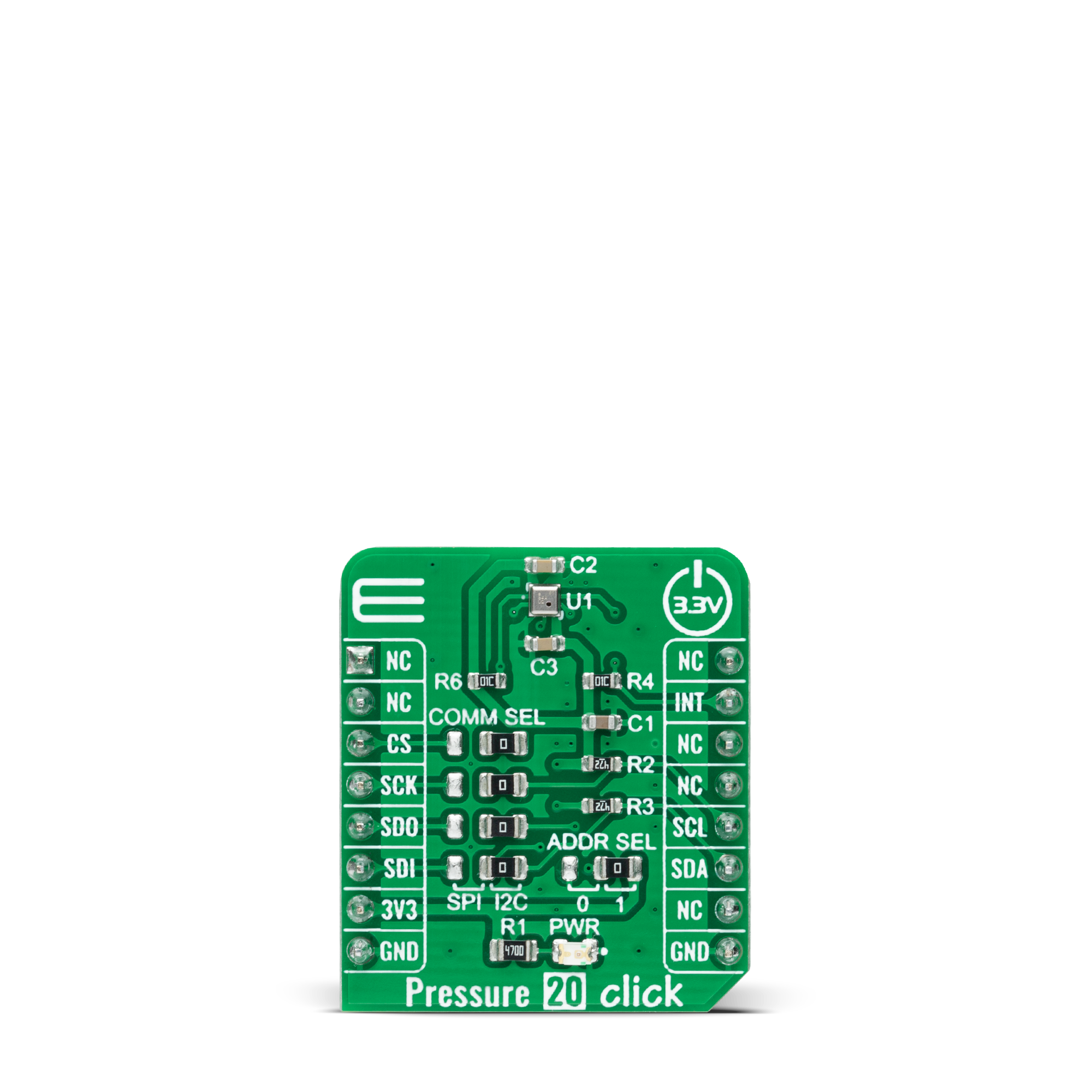
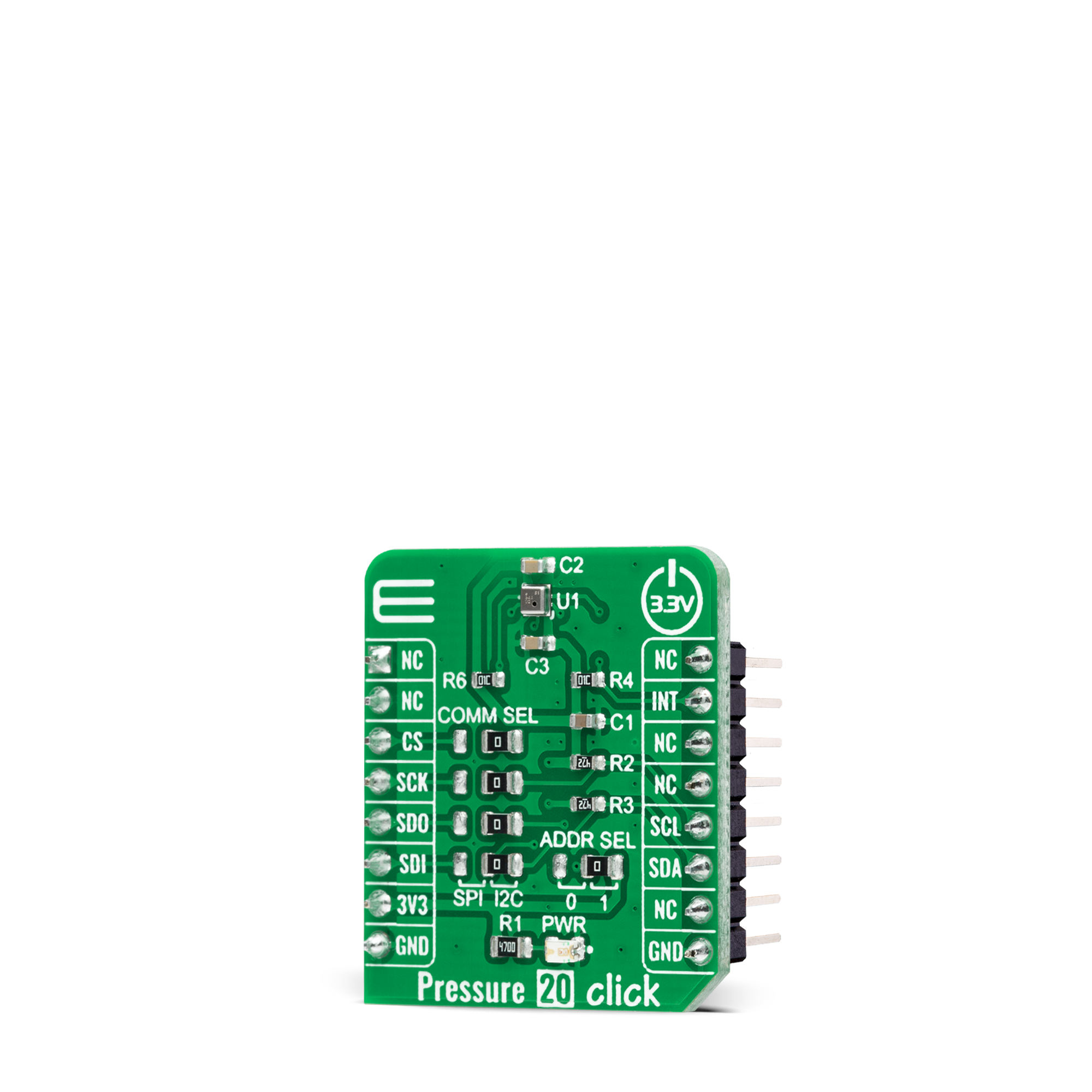
Pressure 20 Click
Dev. board
UNI-DS v8
Compiler
NECTO Studio
MCU
STM32F439ZG
Monitor atmospheric pressure changes anywhere
A
A
Hardware Overview
How does it work?
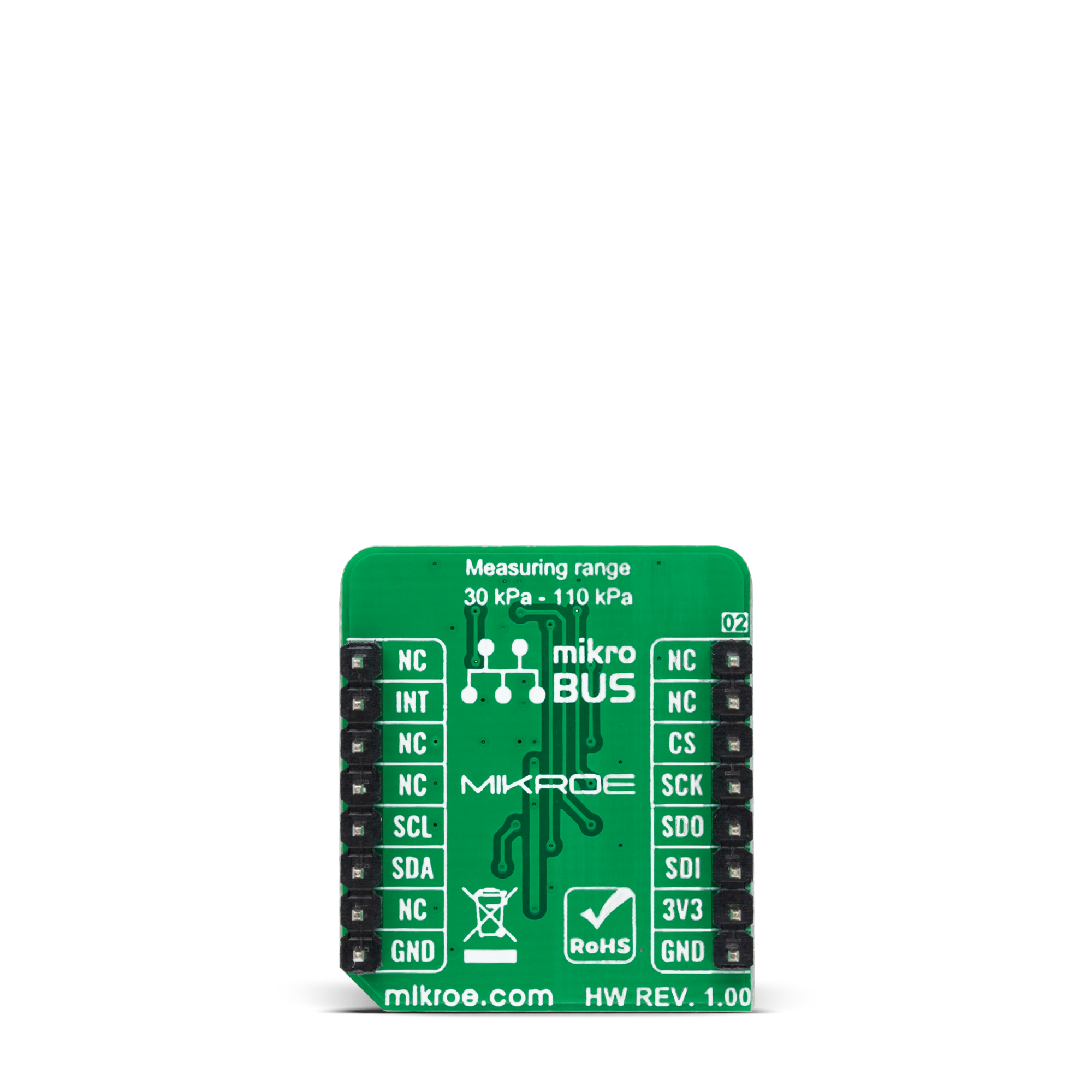
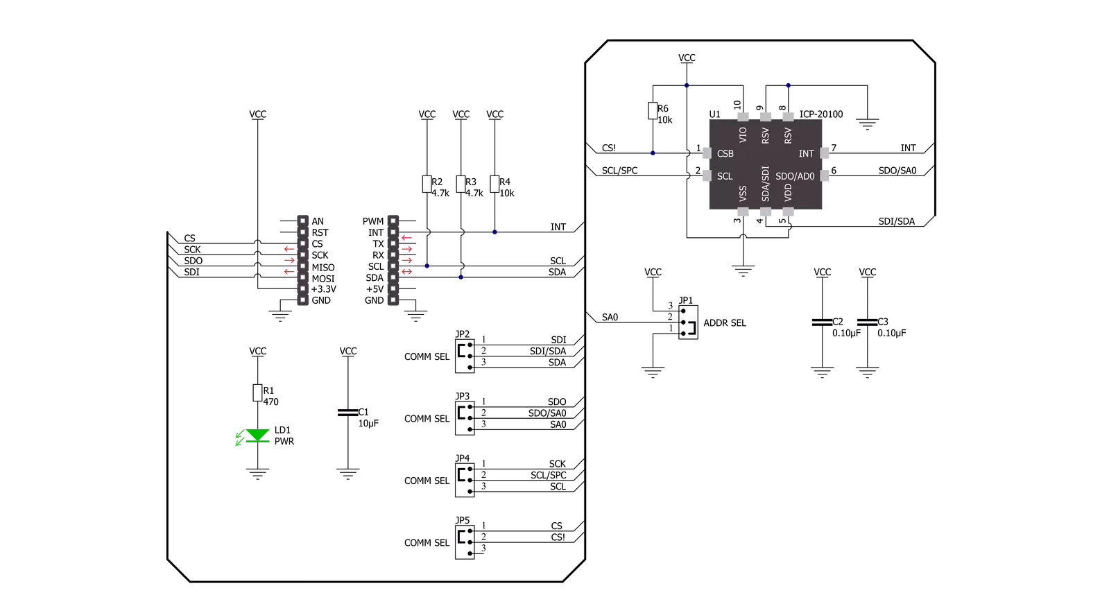
Pressure 20 Click is based on the ICP-20100, a high accuracy, low power, barometric pressure, and temperature sensor solution from TDK InvenSense. It integrates a capacitive pressure sensor for monitoring pressure changes from 30kPa to 110kPa with an accuracy of ±20Pa over a wide operating temperature range. The ICP-20100 achieves the industry's lowest pressure noise of 0.4Pa RMS while attaining the industry's lowest power consumption and retains excellent temperature stability with a temperature coefficient of ±0.4Pa/°C. This MEMS sensor consists of a capacitive pressure sensor whose capacitance changes according to the pressure applied. An integrated temperature sensor on the same MEMS
sensor allows accurate temperature measurements. Other industry-leading features include 20-bit output data, programmable digital filters, calibration, FIFO, and programmable interrupts. Pressure 20 Click allows using I2C and SPI interfaces with a maximum frequency of 1MHz for I2C and 12MHz for SPI communication. The selection can be made by positioning SMD jumpers labeled as COMM SEL in an appropriate position. Note that all the jumpers' positions must be on the same side, or the Click board™ may become unresponsive. While the I2C interface is selected, the ICP-20100 allows choosing the least significant bit (LSB) of its I2C slave address using the SMD jumper labeled ADDR SEL.
This Click board™ also possesses an additional interrupt pin, routed to the INT pin on the mikroBUS™ socket, indicating when a specific interrupt event occurs, such as FIFO overflow/underflow, the threshold over/underrun, and more. This Click board™ can only be operated from a 3.3V logic voltage level. Therefore, the board must perform appropriate logic voltage conversion before using MCUs with different logic levels. However, the Click board™ comes equipped with a library containing functions and an example code that can be used as a reference for further development.
Features overview
Development board
UNI-DS v8 is a development board specially designed for the needs of rapid development of embedded applications. It supports a wide range of microcontrollers, such as different STM32, Kinetis, TIVA, CEC, MSP, PIC, dsPIC, PIC32, and AVR MCUs regardless of their number of pins, and a broad set of unique functions, such as the first-ever embedded debugger/programmer over WiFi. The development board is well organized and designed so that the end-user has all the necessary elements, such as switches, buttons, indicators, connectors, and others, in one place. Thanks to innovative manufacturing technology, UNI-DS v8 provides a fluid and immersive working experience, allowing access anywhere and under any
circumstances at any time. Each part of the UNI-DS v8 development board contains the components necessary for the most efficient operation of the same board. An advanced integrated CODEGRIP programmer/debugger module offers many valuable programming/debugging options, including support for JTAG, SWD, and SWO Trace (Single Wire Output)), and seamless integration with the Mikroe software environment. Besides, it also includes a clean and regulated power supply module for the development board. It can use a wide range of external power sources, including a battery, an external 12V power supply, and a power source via the USB Type-C (USB-C) connector. Communication options such as USB-UART, USB
HOST/DEVICE, CAN (on the MCU card, if supported), and Ethernet is also included. In addition, it also has the well-established mikroBUS™ standard, a standardized socket for the MCU card (SiBRAIN standard), and two display options for the TFT board line of products and character-based LCD. UNI-DS v8 is an integral part of the Mikroe ecosystem for rapid development. Natively supported by Mikroe software tools, it covers many aspects of prototyping and development thanks to a considerable number of different Click boards™ (over a thousand boards), the number of which is growing every day.

Microcontroller Overview
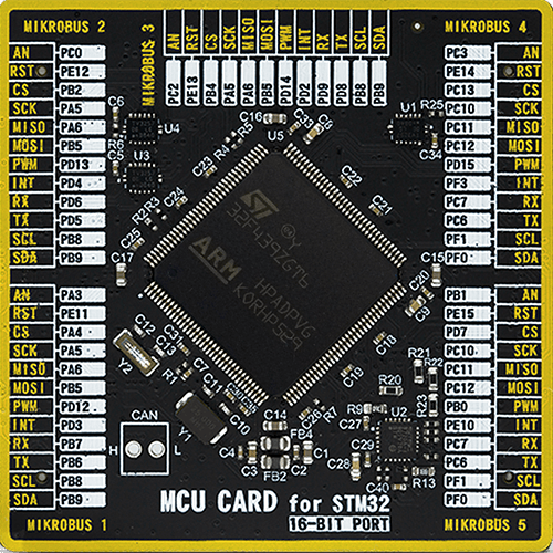
MCU Card / MCU
Type
8th Generation
Architecture
ARM Cortex-M4
MCU Memory (KB)
1024
Silicon Vendor
STMicroelectronics
Pin count
144
RAM (Bytes)
262144
Used MCU Pins
mikroBUS™ mapper
Take a closer look
Click board™ Schematic
Step by step
Project assembly

Start by selecting your development board and Click board™. Begin with the UNI-DS v8 as your development board.


Software Support
Library Description
This library contains API for Pressure 20 Click driver.
Key functions:
pressure20_get_int_pinThis function returns the INT pin logic state.pressure20_clear_interruptsThis function reads and clears the interrupt status register.pressure20_read_dataThis function reads the pressure [mBar] and temperature [Celsius] data.
Open Source
Code example
The complete application code and a ready-to-use project are available through the NECTO Studio Package Manager for direct installation in the NECTO Studio. The application code can also be found on the MIKROE GitHub account.
/*!
 * @file main.c
 * @brief Pressure20 Click example
 *
 * # Description
 * This example demonstrates the use of Pressure 20 Click board by reading and displaying
 * the pressure and temperature data on the USB UART.
 *
 * The demo application is composed of two sections :
 *
 * ## Application Init
 * Initializes the driver and performs the Click default configuration.
 *
 * ## Application Task
 * Waits for the data ready interrupt, clears the interrupts and than reads
 * the pressure [mBar] and temperature [Celsius] data and displays them on the USB UART
 * at the set output data rate (25Hz by default).
 *
 * @author Stefan Filipovic
 *
 */

#include "board.h"
#include "log.h"
#include "pressure20.h"

static pressure20_t pressure20;
static log_t logger;

void application_init ( void )
{
    log_cfg_t log_cfg;  /**< Logger config object. */
    pressure20_cfg_t pressure20_cfg;  /**< Click config object. */

    /**
     * Logger initialization.
     * Default baud rate: 115200
     * Default log level: LOG_LEVEL_DEBUG
     * @note If USB_UART_RX and USB_UART_TX
     * are defined as HAL_PIN_NC, you will
     * need to define them manually for log to work.
     * See @b LOG_MAP_USB_UART macro definition for detailed explanation.
     */
    LOG_MAP_USB_UART( log_cfg );
    log_init( &logger, &log_cfg );
    log_info( &logger, " Application Init " );

    // Click initialization.
    pressure20_cfg_setup( &pressure20_cfg );
    PRESSURE20_MAP_MIKROBUS( pressure20_cfg, MIKROBUS_1 );
    err_t init_flag  = pressure20_init( &pressure20, &pressure20_cfg );
    if ( ( I2C_MASTER_ERROR == init_flag ) || ( SPI_MASTER_ERROR == init_flag ) )
    {
        log_error( &logger, " Communication init." );
        for ( ; ; );
    }

    if ( PRESSURE20_ERROR == pressure20_default_cfg ( &pressure20 ) )
    {
        log_error( &logger, " Default configuration." );
        for ( ; ; );
    }

    log_info( &logger, " Application Task " );
}

void application_task ( void )
{
    // Wait for the data ready interrupt
    while ( pressure20_get_int_pin ( &pressure20 ) );
    float pressure, temperature;
    if ( ( PRESSURE20_OK == pressure20_clear_interrupts ( &pressure20 ) ) &&
         ( PRESSURE20_OK == pressure20_read_data ( &pressure20, &pressure, &temperature ) ) )
    {
        log_printf ( &logger, " Pressure: %.1f mBar\r\n", pressure );
        log_printf ( &logger, " Temperature: %.2f C\r\n\n", temperature );
    }
}

int main ( void )
{
    /* Do not remove this line or clock might not be set correctly. */
    #ifdef PREINIT_SUPPORTED
    preinit();
    #endif

    application_init( );

    for ( ; ; )
    {
        application_task( );
    }

    return 0;
}

// ------------------------------------------------------------------------ END


