使用ADS1230和PIC32MZ1024EFH064测量物体的力或重量
力计
已发布 6月 26, 2024
点击板
Load Cell 7 Click
开发板
PIC32MZ clicker
编译器
NECTO Studio
微控制器单元
PIC32MZ1024EFH064
桥接传感应用的完整前端解决方案。
A
A
硬件概览
它是如何工作的?
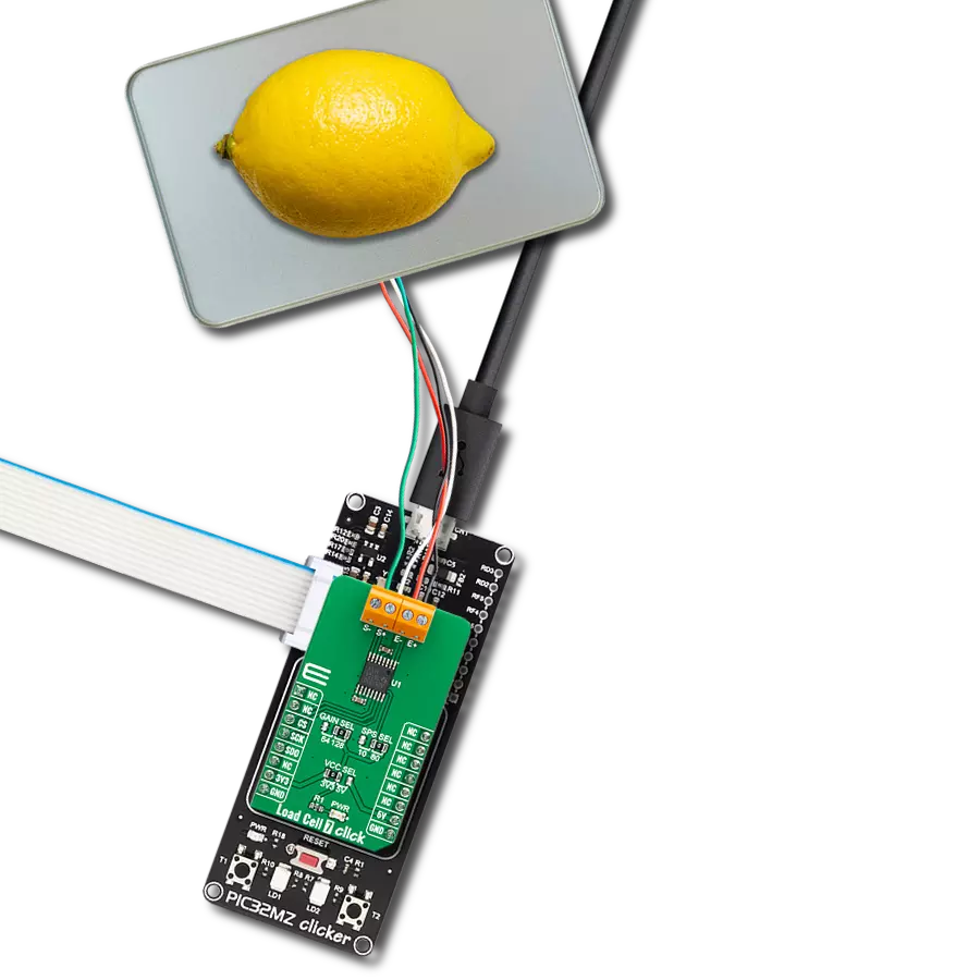
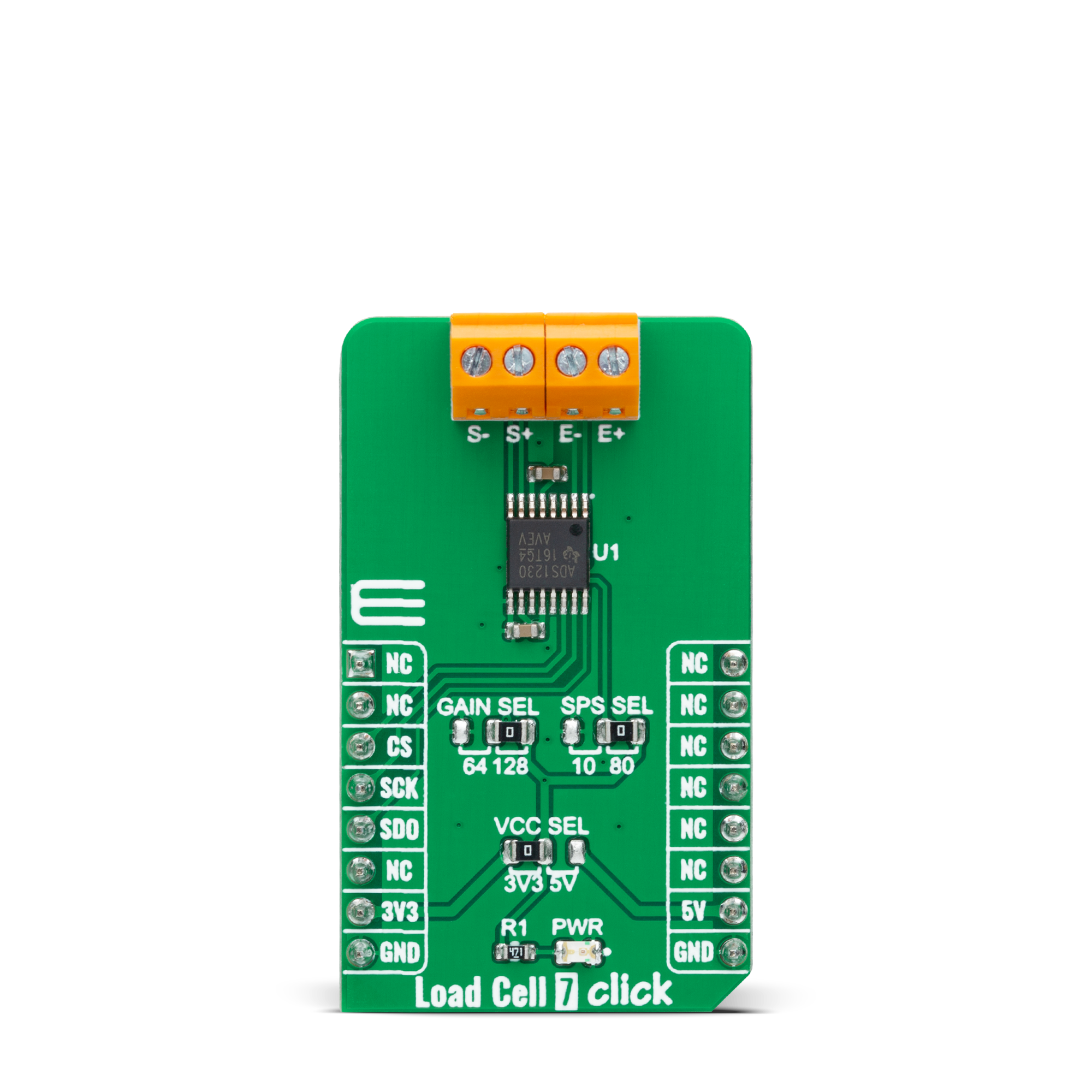
Load Cell 7 Click 基于 ADS1230,这是一款来自德州仪器的高精度、低噪声、低功耗的 20 位 ΣΔ ADC,具有卓越的噪声性能。它包括一个低噪声 PGA、内部振荡器、三级 ΔΣ 调制器和四级数字滤波器,从而为桥接传感器应用提供完整的前端解决方案。ADS1230 易于配置,所有数字控制通过专用引脚完成,无需可编程寄存器。来自 ADS1230 的转换数据通过 SPI 串行接口发送到 MCU,数字信息被转换为重量。低噪声 PGA 具有可选择的增益,通过板载标记为 GAIN
SEL 的 SMD 跳线设置为 64 和 128,分别支持 ±39mV 或 ±19.5mV 的全量程差分输入。此外,当需要更高速度时,数据可以以 10SPS 输出,具有出色的 50Hz 和 60Hz 抑制,或以 80SPS 输出。板载标记为 SPS SEL 的 SMD 跳线可以选择此功能,将其放置在标记为 10 和 80 的适当位置。ADS1230 可以进入低功耗待机模式或完全关闭的掉电模式。此 Click board™ 使用四线制负载单元配置,具有两个感应引脚和两个输出连接。连接到 AD7780 参考输
入的负载单元差分 S 线创建了一个免疫低频电源激励电压变化的比例配置。这些感应引脚连接到惠斯通电桥的高低两侧,无论由于布线电阻造成的电压降如何,电压都可以精确测量。此 Click board™ 可在 3.3V 或 5V 逻辑电压水平下工作,通过 VCC SEL 跳线选择。这种方式使得 3.3V 和 5V 的 MCU 都可以正确使用通信线路。此外,这款 Click board™ 配备了一个包含易于使用的函数库和示例代码的库,可以作为进一步开发的参考。
功能概述
开发板
PIC32MZ Clicker 是一款紧凑型入门开发板,它将 Click 板™的灵活性带给您喜爱的微控制器,使其成为实现您想法的完美入门套件。它配备了一款板载 32 位带有浮点单元的 Microchip PIC32MZ 微控制器,一个 USB 连接器,LED 指示灯,按钮,一个 mikroProg 连接器,以及一个用于与外部电子设备接口的头部。得益于其紧凑的设计和清晰易识别的丝网标记,它提供了流畅且沉浸式的工作体验,允许在任
何情况下、任何地方都能访问。PIC32MZ Clicker 开 发套件的每个部分都包含了使同一板块运行最高效的必要组件。除了可以选择 PIC32MZ Clicker 的编程方式,使用 USB HID mikroBootloader 或通过外部 mikroProg 连接器为 PIC,dsPIC 或 PIC32 编程外,Clicker 板还包括一个干净且调节过的开发套件电源供应模块。USB Micro-B 连接可以提供多达 500mA 的电流,这足以操作所有板载和附加模块。所有
mikroBUS™ 本身支持的通信方法都在这块板上,包 括已经建立良好的 mikroBUS™ 插槽、重置按钮以及若干按钮和 LED 指示灯。PIC32MZ Clicker 是 Mikroe 生态系统的一个组成部分,允许您在几分钟内创建新的应用程序。它由 Mikroe 软件工具原生支持,得益于大量不同的 Click 板™(超过一千块板),其数量每天都在增长,它涵盖了原型制作的许多方面。

微控制器概述
MCU卡片 / MCU

建筑
PIC32
MCU 内存 (KB)
1024
硅供应商
Microchip
引脚数
64
RAM (字节)
524288
使用的MCU引脚
mikroBUS™映射器
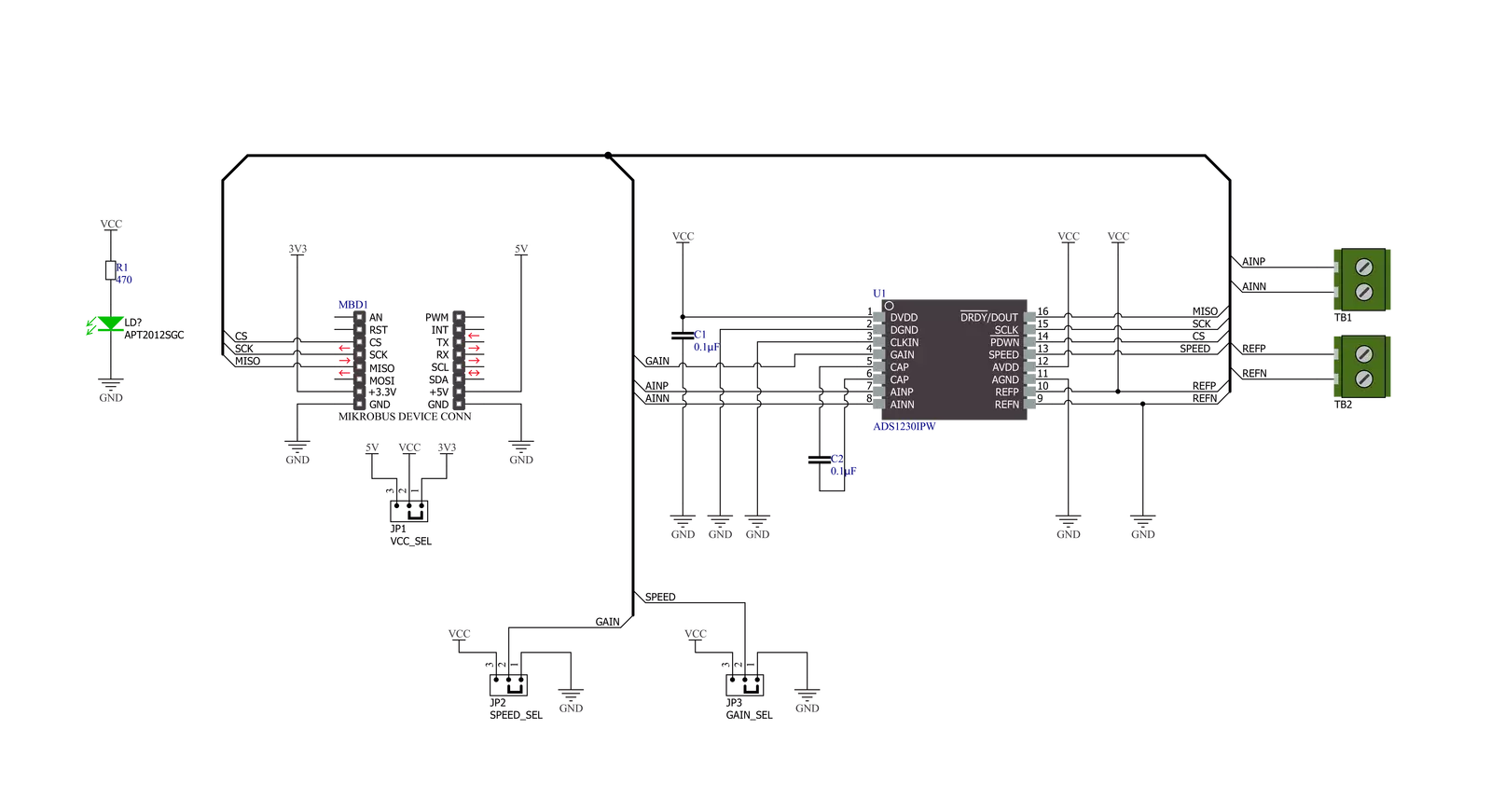
“仔细看看!”
Click board™ 原理图
一步一步来
项目组装

从选择您的开发板和Click板™开始。以PIC32MZ clicker作为您的开发板开始。


实时跟踪您的结果
应用程序输出
1. 应用程序输出 - 在调试模式下,“应用程序输出”窗口支持实时数据监控,直接提供执行结果的可视化。请按照提供的教程正确配置环境,以确保数据正确显示。

2. UART 终端 - 使用UART Terminal通过USB to UART converter监视数据传输,实现Click board™与开发系统之间的直接通信。请根据项目需求配置波特率和其他串行设置,以确保正常运行。有关分步设置说明,请参考提供的教程。

3. Plot 输出 - Plot功能提供了一种强大的方式来可视化实时传感器数据,使趋势分析、调试和多个数据点的对比变得更加直观。要正确设置,请按照提供的教程,其中包含使用Plot功能显示Click board™读数的分步示例。在代码中使用Plot功能时,请使用以下函数:plot(insert_graph_name, variable_name);。这是一个通用格式,用户需要将“insert_graph_name”替换为实际图表名称,并将“variable_name”替换为要显示的参数。

软件支持
库描述
该库包含 Load Cell 7 Click 驱动程序的 API。
关键功能:
loadcell7_tare_scale- 此函数计算 @b ctx->tare_scale,即空容器的原始 ADC 读数。loadcell7_calibrate_weight- 此函数通过计算输入校准重量的 @b ctx->weight_scale 来校准重量。loadcell7_get_weight- 此函数计算货物的重量(单位:克)。
开源
代码示例
完整的应用程序代码和一个现成的项目可以通过NECTO Studio包管理器直接安装到NECTO Studio。 应用程序代码也可以在MIKROE的GitHub账户中找到。
/*!
 * @file main.c
 * @brief Load Cell 7 Click example
 *
 * # Description
 * This example demonstrates the use of Load Cell 7 Click by measuring the weight
 * in grams of the goods from the load cell sensor connected to the Click board.
 *
 * The demo application is composed of two sections :
 *
 * ## Application Init
 * Initializes the driver and reads the tare scale of the empty container, and after
 * that, it calibrates the weight scale with a known calibration weight.
 *
 * ## Application Task
 * Reads the net weight of the goods in grams approximately once per second and logs the
 * results on the USB UART.
 *
 * @author Stefan Filipovic
 *
 */

#include "board.h"
#include "log.h"
#include "loadcell7.h"

// Enter below the weight in grams of the goods with a known weight which
// you will use to calibrate the scale weight.
#define LOADCELL7_CALIBRATION_WEIGHT_G  1000.0

static loadcell7_t loadcell7;
static log_t logger;

void application_init ( void )
{
    log_cfg_t log_cfg;  /**< Logger config object. */
    loadcell7_cfg_t loadcell7_cfg;  /**< Click config object. */

    /**
     * Logger initialization.
     * Default baud rate: 115200
     * Default log level: LOG_LEVEL_DEBUG
     * @note If USB_UART_RX and USB_UART_TX
     * are defined as HAL_PIN_NC, you will
     * need to define them manually for log to work.
     * See @b LOG_MAP_USB_UART macro definition for detailed explanation.
     */
    LOG_MAP_USB_UART( log_cfg );
    log_init( &logger, &log_cfg );
    log_info( &logger, " Application Init " );

    // Click initialization.
    loadcell7_cfg_setup( &loadcell7_cfg );
    LOADCELL7_MAP_MIKROBUS( loadcell7_cfg, MIKROBUS_1 );
    if ( SPI_MASTER_ERROR == loadcell7_init( &loadcell7, &loadcell7_cfg ) )
    {
        log_error( &logger, " Communication init." );
        for ( ; ; );
    }

    log_printf( &logger, " Remove all goods from the scale in the following 5 sec.\r\n");
    Delay_ms ( 1000 );
    Delay_ms ( 1000 );
    Delay_ms ( 1000 );
    Delay_ms ( 1000 );
    Delay_ms ( 1000 );
    log_printf( &logger, " Calculating tare scale...\r\n");
    if ( LOADCELL7_OK == loadcell7_tare_scale ( &loadcell7 ) )
    {
        log_printf( &logger, " Tarring complete!\r\n\n");
    }
    else
    {
        log_error( &logger, " Calculating tare scale.");
        for ( ; ; );
    }

    log_printf( &logger, " Place a %ug calibration weight on the scale in the following 5 sec.\r\n",
                ( uint16_t ) LOADCELL7_CALIBRATION_WEIGHT_G );
    Delay_ms ( 1000 );
    Delay_ms ( 1000 );
    Delay_ms ( 1000 );
    Delay_ms ( 1000 );
    Delay_ms ( 1000 );
    log_printf( &logger, " Calibrating weight...\r\n");
    if ( LOADCELL7_OK == loadcell7_calibrate_weight ( &loadcell7, LOADCELL7_CALIBRATION_WEIGHT_G ) )
    {
        log_printf( &logger, " Calibration complete!\r\n\n");
    }
    else
    {
        log_error( &logger, " Calibrating weight.");
        for ( ; ; );
    }

    log_info( &logger, " Application Task " );
}

void application_task ( void )
{
    float weight;
    if ( LOADCELL7_OK == loadcell7_get_weight ( &loadcell7, &weight ) )
    {
        log_printf(&logger, " Weight : %.2f g\r\n", weight );
    }
}

int main ( void )
{
    /* Do not remove this line or clock might not be set correctly. */
    #ifdef PREINIT_SUPPORTED
    preinit();
    #endif

    application_init( );

    for ( ; ; )
    {
        application_task( );
    }

    return 0;
}

// ------------------------------------------------------------------------ END


