使用MAX11270和PIC18F57Q43实现高效精准的重量测量,节省时间
释放每一克的潜力

已发布 6月 24, 2024
点击板
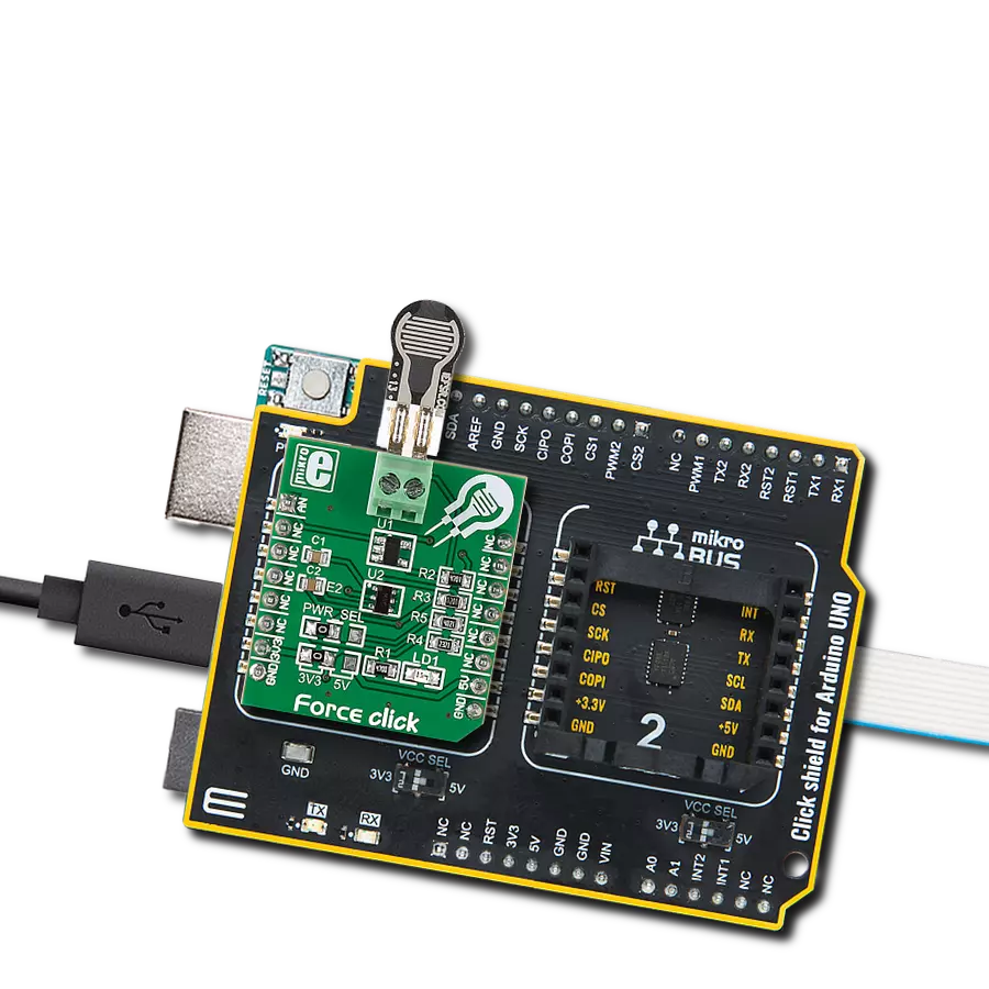
Load Cell 6 Click
开发板
Curiosity Nano with PIC18F57Q43
编译器
NECTO Studio
微控制器单元
PIC18F57Q43
通过一致的重量追踪来改进库存管理。
A
A
硬件概览
它是如何工作的?
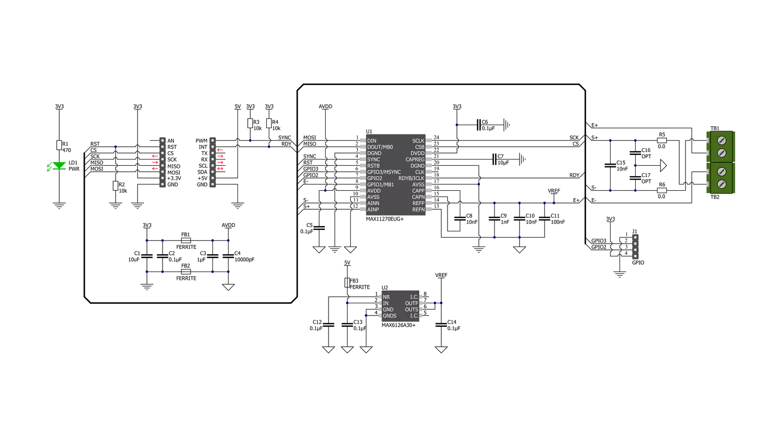
Load Cell 6 Click基于MAX11270,这是Analog Devices提供的一款引脚可编程、超低功耗的24位ΣΔ ADC,具有非常高的动态范围。MAX11270在消耗超低10mW功耗的同时,实现了卓越的130dB SNR。它允许用户选择增益设置在1x到128x之间的可编程增益放大器、单位增益缓冲器或将信号直接连接到ΔΣ采样网络。此ADC能够解析模拟输入的微伏级变化,非常适合地震、仪器和ATE应用。MAX11270测量缓冲、直接连接或PGA中的差分模拟输入(S+,S-)。默认配置为直接连接,PGA和输入缓冲器关闭。这些可选缓冲器将信号输入与开关电容采样网络隔离,使MAX11270可以与高阻抗源一起使用,而不会影响可用的动态范围。ADC
输入范围可编程为单极(0到VREF)范围,由通过MAX6126获得的参考电压值设置,MAX6126是一款3V高精度电压参考,也路由到E+端子。Load Cell 6 Click通过标准SPI接口与MCU通信,支持高达5MHz的时钟速度。MAX11270可以通过SPI接口访问的内部寄存器进行高度配置。它有两种模式:转换模式或寄存器访问模式,由命令字节选择。这些寄存器包括PGA增益选择、偏移和增益校准,以及可扩展的采样率以优化性能。它还提供软件可选的输出数据速率,高达12.8 kps无数据延迟和64 kps连续,以优化数据速率和噪声。此外,连接到mikroBUS™插座RST引脚的复位引脚用于完全复位所有数字功能,导致上电复位默认状态,而
连接到mikroBUS™插座INT引脚的标记为RDY的数据就绪信号在数据准备好时通知主机MCU。同步复位信号也被使用,标记为SYN,并连接到mikroBUS™插座的PWM引脚,它重置数字滤波器和调制器。它还具有一个GPIO头,包含两个来自MAX11270的通用引脚,可由用户配置。尽管该板使用了两个mikroBUS™电源轨,但此Click board™只能在3.3V逻辑电压水平下运行(5V仅用作电压参考电源)。在使用不同逻辑电平的MCU之前,必须进行适当的逻辑电压电平转换。此外,此Click board™配备了包含易于使用的函数和示例代码的库,可用作进一步开发的参考。


功能概述
开发板
PIC18F57Q43 Curiosity Nano 评估套件是一款尖端的硬件平台,旨在评估 PIC18-Q43 系列内的微控制器。其设计的核心是包含了功能强大的 PIC18F57Q43 微控制器(MCU),提供先进的功能和稳健的性能。这个评估套件的关键特点包括一个黄 色用户 LED 和一个响应灵敏的机械用户开关,提供无
缝的交互和测试。为一个 32.768kHz 水晶振荡器足迹提供支持,确保精准的定时能力。套件内置的调试器拥有一个绿色电源和状态 LED,使编程和调试变得直观高效。此外,增强其实用性的还有虚拟串行端口 (CDC)和一个调试 GPIO 通道(DGI GPIO),提供广泛的连接选项。该套件通过 USB 供电,拥有由
MIC5353 LDO 调节器提供支持的可调目标电压功能,确保在 1.8V 至 5.1V 的输出电压范围内稳定运行,最大输出电流为 500mA,受环境温度和电压限制。

微控制器概述
MCU卡片 / MCU

建筑
PIC
MCU 内存 (KB)
128
硅供应商
Microchip
引脚数
48
RAM (字节)
8196
你完善了我!
配件
Curiosity Nano Base for Click boards 是一款多功能硬件扩展平台,专为简化 Curiosity Nano 套件与扩展板之间的集成而设计,特别针对符合 mikroBUS™ 标准的 Click 板和 Xplained Pro 扩展板。这款创新的基板(屏蔽板)提供了无缝的连接和扩展可能性,简化了实验和开发过程。主要特点包括从 Curiosity Nano 套件提供 USB 电源兼容性,以及为增强灵活性而提供的另一种外部电源输入选项。板载锂离子/锂聚合物充电器和管理电路确保电池供电应用的平稳运行,简化了使用和管理。此外,基板内置了一个固定的 3.3V 电源供应单元,专用于目标和 mikroBUS™ 电源轨,以及一个固定的 5.0V 升压转换器,专供 mikroBUS™ 插座的 5V 电源轨,为各种连接设备提供稳定的电力供应。

使用的MCU引脚
mikroBUS™映射器
“仔细看看!”
Click board™ 原理图
一步一步来
项目组装

从选择您的开发板和Click板™开始。以Curiosity Nano with PIC18F57Q43作为您的开发板开始。


实时跟踪您的结果
应用程序输出
1. 应用程序输出 - 在调试模式下,“应用程序输出”窗口支持实时数据监控,直接提供执行结果的可视化。请按照提供的教程正确配置环境,以确保数据正确显示。

2. UART 终端 - 使用UART Terminal通过USB to UART converter监视数据传输,实现Click board™与开发系统之间的直接通信。请根据项目需求配置波特率和其他串行设置,以确保正常运行。有关分步设置说明,请参考提供的教程。

3. Plot 输出 - Plot功能提供了一种强大的方式来可视化实时传感器数据,使趋势分析、调试和多个数据点的对比变得更加直观。要正确设置,请按照提供的教程,其中包含使用Plot功能显示Click board™读数的分步示例。在代码中使用Plot功能时,请使用以下函数:plot(insert_graph_name, variable_name);。这是一个通用格式,用户需要将“insert_graph_name”替换为实际图表名称,并将“variable_name”替换为要显示的参数。

软件支持
库描述
该库包含 Load Cell 6 Click 驱动程序的 API。
关键功能:
loadcell6_get_weight- Load Cell 6 获取重量功能loadcell6_calibration- Load Cell 6 校准功能loadcell6_tare- Load Cell 6 去皮功能
开源
代码示例
完整的应用程序代码和一个现成的项目可以通过NECTO Studio包管理器直接安装到NECTO Studio。 应用程序代码也可以在MIKROE的GitHub账户中找到。
/*!
* @file main.c
* @brief LoadCell6 Click example
*
* # Description
* This library contains API for the Load Cell 6 Click driver.
* The library initializes and defines the SPI bus drivers to read status and ADC data.
* The library also includes a function for tare, calibration and weight measurement.
*
* The demo application is composed of two sections :
*
* ## Application Init
* Initialization of SPI module and log UART.
* After driver initialization, app performs the power on
* sets tare the scale, calibrate scale and start measurements.
*
* ## Application Task
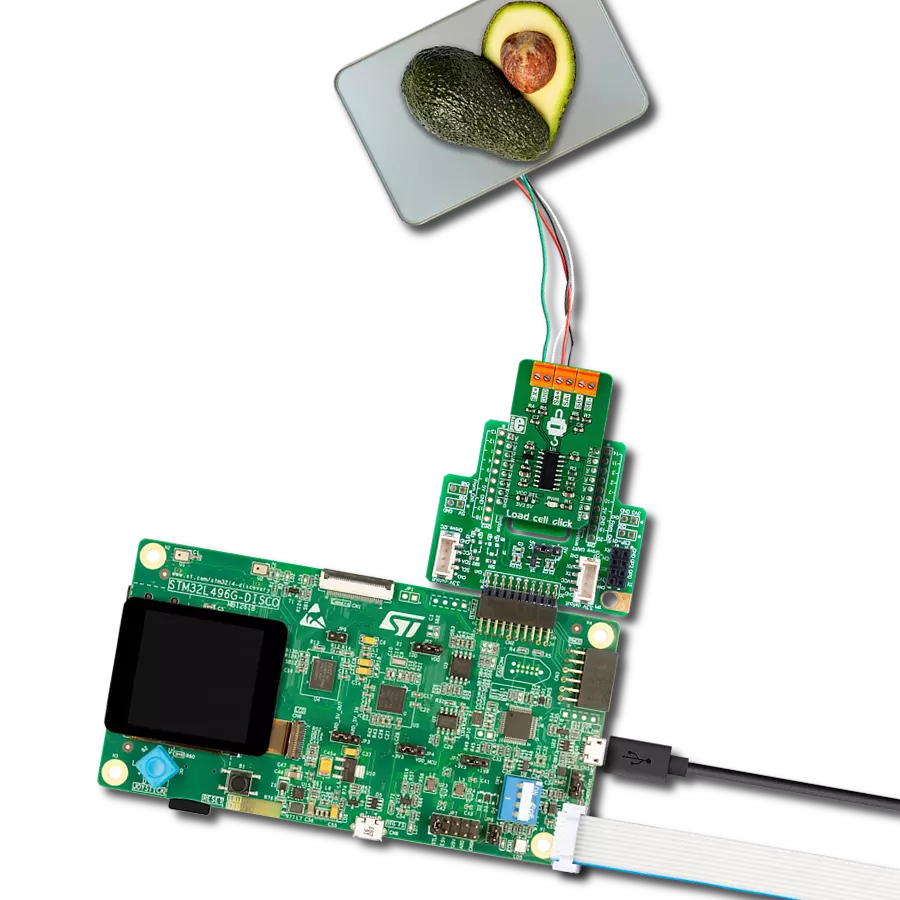
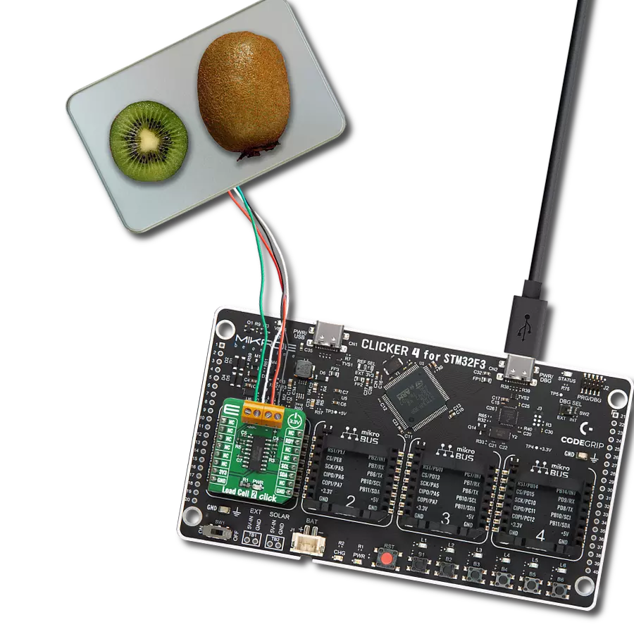
* This is an example that demonstrates the use of the Load Cell 6 Click board™.
* The Load Cell 6 Click board™ can be used to measure weight and
* shows the measurement of scales in grams [ g ].
* Results are being sent to the Usart Terminal where you can track their changes.
*
* @author Nenad Filipovic
*
*/
#include "board.h"
#include "log.h"
#include "loadcell6.h"
static loadcell6_t loadcell6;
static log_t logger;
static loadcell6_data_t cell_data;
void application_init ( void )
{
log_cfg_t log_cfg; /**< Logger config object. */
loadcell6_cfg_t loadcell6_cfg; /**< Click config object. */
/**
* Logger initialization.
* Default baud rate: 115200
* Default log level: LOG_LEVEL_DEBUG
* @note If USB_UART_RX and USB_UART_TX
* are defined as HAL_PIN_NC, you will
* need to define them manually for log to work.
* See @b LOG_MAP_USB_UART macro definition for detailed explanation.
*/
LOG_MAP_USB_UART( log_cfg );
log_init( &logger, &log_cfg );
log_info( &logger, " Application Init " );
// Click initialization.
loadcell6_cfg_setup( &loadcell6_cfg );
LOADCELL6_MAP_MIKROBUS( loadcell6_cfg, MIKROBUS_1 );
if ( SPI_MASTER_ERROR == loadcell6_init( &loadcell6, &loadcell6_cfg ) )
{
log_error( &logger, " Communication init." );
for ( ; ; );
}
if ( LOADCELL6_ERROR == loadcell6_default_cfg( &loadcell6 ) )
{
log_error( &logger, " Default configuration." );
for ( ; ; );
}
Delay_ms ( 1000 );
log_printf( &logger, "-------------------------\r\n");
log_printf( &logger, " Tare the scale : \r\n");
log_printf( &logger, "- - - - - - - - - - - - -\r\n");
log_printf( &logger, " >> Remove all object << \r\n");
log_printf( &logger, "- - - - - - - - - - - - -\r\n");
log_printf( &logger, " In the following 10 sec \r\n");
log_printf( &logger, " please remove all object\r\n");
log_printf( &logger, " from the scale. \r\n");
// 10 seconds delay
Delay_ms ( 1000 );
Delay_ms ( 1000 );
Delay_ms ( 1000 );
Delay_ms ( 1000 );
Delay_ms ( 1000 );
Delay_ms ( 1000 );
Delay_ms ( 1000 );
Delay_ms ( 1000 );
Delay_ms ( 1000 );
Delay_ms ( 1000 );
log_printf( &logger, "-------------------------\r\n");
log_printf( &logger, " Start tare scales \r\n");
loadcell6_tare( &loadcell6, &cell_data );
Delay_ms ( 500 );
log_printf( &logger, "-------------------------\r\n");
log_printf( &logger, " Tarring is complete \r\n");
log_printf( &logger, "-------------------------\r\n");
log_printf( &logger, " Calibrate Scale : \r\n");
log_printf( &logger, "- - - - - - - - - - - - -\r\n");
log_printf( &logger, " >>> Load etalon <<< \r\n");
log_printf( &logger, "- - - - - - - - - - - - -\r\n");
log_printf( &logger, " In the following 10 sec \r\n");
log_printf( &logger, "place 200g weight etalon\r\n");
log_printf( &logger, " on the scale for \r\n");
log_printf( &logger, " calibration purpose. \r\n");
// 10 seconds delay
Delay_ms ( 1000 );
Delay_ms ( 1000 );
Delay_ms ( 1000 );
Delay_ms ( 1000 );
Delay_ms ( 1000 );
Delay_ms ( 1000 );
Delay_ms ( 1000 );
Delay_ms ( 1000 );
Delay_ms ( 1000 );
Delay_ms ( 1000 );
log_printf( &logger, "-------------------------\r\n");
log_printf( &logger, " Start calibration \r\n");
if ( LOADCELL6_OK == loadcell6_calibration( &loadcell6, LOADCELL6_WEIGHT_200G, &cell_data ) )
{
log_printf( &logger, "-------------------------\r\n");
log_printf( &logger, " Calibration Done \r\n");
log_printf( &logger, "- - - - - - - - - - - - -\r\n");
log_printf( &logger, " >>> Remove etalon <<< \r\n");
log_printf( &logger, "- - - - - - - - - - - - -\r\n");
log_printf( &logger, " In the following 5 sec \r\n");
log_printf( &logger, " remove 200g weight \r\n");
log_printf( &logger, " etalon on the scale. \r\n");
Delay_ms ( 1000 );
Delay_ms ( 1000 );
Delay_ms ( 1000 );
Delay_ms ( 1000 );
Delay_ms ( 1000 );
}
else
{
log_printf( &logger, "-------------------------\r\n");
log_printf( &logger, " Calibration Error \r\n");
for ( ; ; );
}
log_printf( &logger, "-------------------------\r\n");
log_printf( &logger, " Start measurements : \r\n");
log_printf( &logger, "-------------------------\r\n");
}
void application_task ( void )
{
static float weight_g;
if ( LOADCELL6_OK == loadcell6_get_weight( &loadcell6, &cell_data, &weight_g ) )
{
log_printf(&logger, " Weight : %.2f g\r\n", weight_g );
}
}
int main ( void )
{
/* Do not remove this line or clock might not be set correctly. */
#ifdef PREINIT_SUPPORTED
preinit();
#endif
application_init( );
for ( ; ; )
{
application_task( );
}
return 0;
}
// ------------------------------------------------------------------------ END
额外支持
资源
类别:力