使用AD9834和STM32L496AG塑造您的信号
频率激励/波形生成
已发布 7月 22, 2025
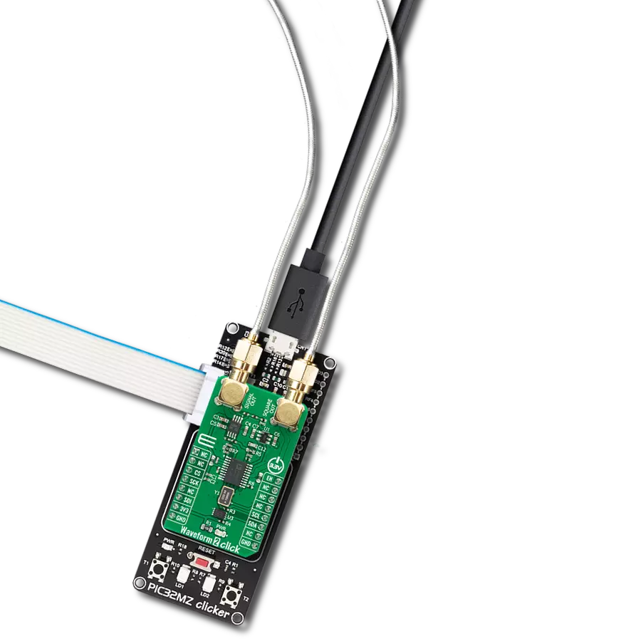
点击板
Waveform 2 Click
开发板
Discovery kit with STM32L496AG MCU
编译器
NECTO Studio
微控制器单元
STM32L496AG
通过先进的波形发生器实现正弦和三角波输出以及频率相位调谐和调制。
A
A
硬件概览
它是如何工作的?
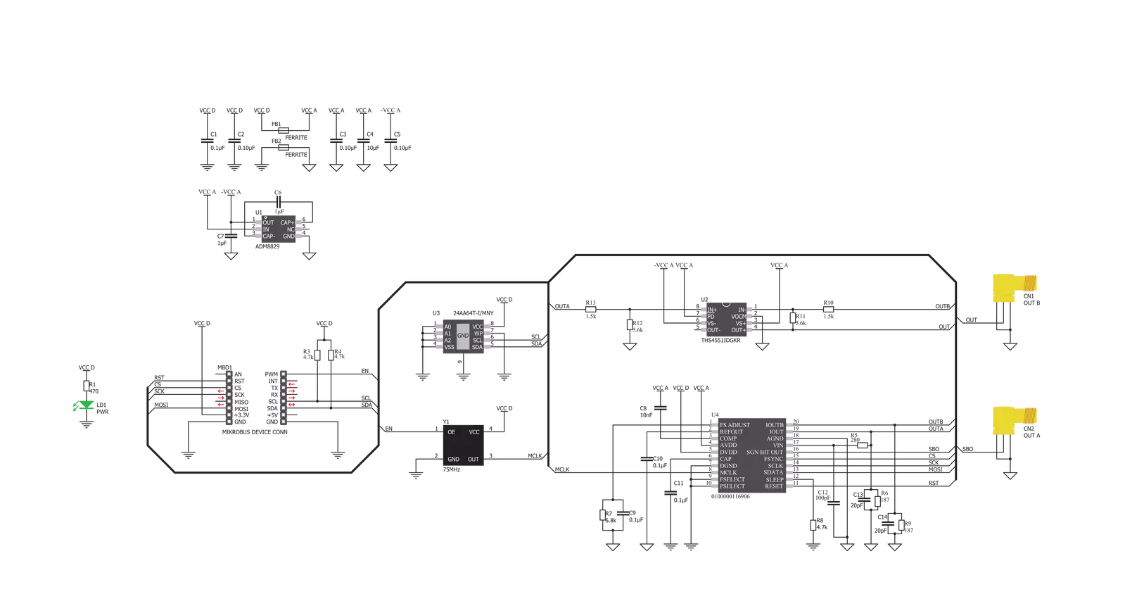
Waveform 2 Click 基于 Analog Devices 的 AD9834,这是一款 75 MHz 低功耗 DDS 设备,能够产生高性能的正弦波、三角波和方波输出。AD9834 可以实现多种简单和复杂的调制方案,这些调制方案在数字域中完全实现,允许使用 DSP 技术精确实现复杂的调制算法。它包含一个通过 SPI 串行接口访问的 16 位控制寄存器,可根据用户的需求设置 AD9834 的操作方式。AD9834 的内部电路包括数控振荡器 (NCO)、频率和相位调制器、SIN ROM、DAC、比较器和稳压器。AD9834 的输出通过 RC 网络滤波,然后通过 THS4551 放大,THS4551 是一个差分放大器,提供了从单端源到德州仪器的高精度模数转换器所需的差分输
出的简便接口。AD9834 的输出信号沿两条路径传输。当发生器的输出波形为正弦波或三角波时,一条路径被路由到标记为 Signal Out 的输出连接器;而当发生器的输出波形为方波时,另一条路径被路由到标记为 Square Out 的输出连接器。除了正电源电压要求外,THS4551 放大器还需要负电源电压,这是通过 ADM8829 实现的,ADM8829 是一个电荷泵电压逆变器,用于从 Analog Devices 的正输入生成负电源电压。该 Click 板™ 还具有 75MHz 的外部振荡器,由 mikroBUS™ 插座的 EN 引脚启用,代表 AD9834 可以接受的最大频率。75MHz 时钟在高频率下产生最干净的正弦波形,而低频率则会产生误差。除了这些功能
外,Waveform 2 Click 还具有 EEPROM 存储器 IC 24AA64,这是 Microchip 的一款 I2C 可配置的 64K 串行 EEPROM,可用于各种存储应用。Waveform 2 Click 使用兼容标准 SPI、QSPI™ 和 MICROWIRE™ 的 3 线 SPI 串行接口与 MCU 通信,操作时钟速率最高可达 40 MHz。此外,它还具备复位功能,这是 AD9834 初始化过程中所需的,通过 mikroBUS™ 插座的 RST 引脚实现和路由。该 Click 板™ 只能在 3.3V 逻辑电压水平下工作。在使用不同逻辑电平的 MCU 之前,必须执行适当的逻辑电压电平转换。不过,该 Click 板™ 配备了包含易于使用的函数库和示例代码的库,可用作进一步开发的参考。


功能概述
开发板
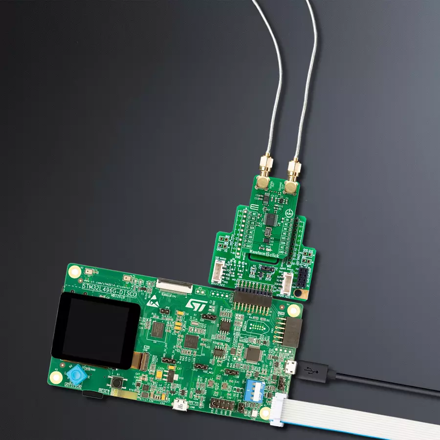
32L496GDISCOVERY Discovery 套件是一款功能全面的演示和开发平台,专为搭载 Arm® Cortex®-M4 内核的 STM32L496AG 微控制器设计。该套件适用于需要在高性能、先进图形处理和超低功耗之间取得平衡的应用,支持无缝原型开发,适用于各种嵌入式解决方案。STM32L496AG 采用创新的节能架构,集成
了扩展 RAM 和 Chrom-ART 图形加速器,在提升图形性能的同时保持低功耗,使其特别适用于音频处理、图形用户界面和实时数据采集等对能效要求较高的应用。为了简化开发流程,该开发板配备了板载 ST-LINK/V2-1 调试器/编程器,提供即插即用的调试和编程体验,使用户无需额外硬件即可轻松加载、调
试和测试应用程序。凭借低功耗特性、增强的内存能力以及内置调试工具,32L496GDISCOVERY 套件是开发先进嵌入式系统、实现高效能解决方案的理想选择。

微控制器概述
MCU卡片 / MCU

建筑
ARM Cortex-M4
MCU 内存 (KB)
1024
硅供应商
STMicroelectronics
引脚数
169
RAM (字节)
327680
使用的MCU引脚
mikroBUS™映射器
“仔细看看!”
Click board™ 原理图
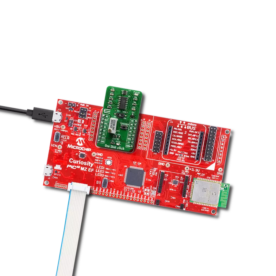
一步一步来
项目组装

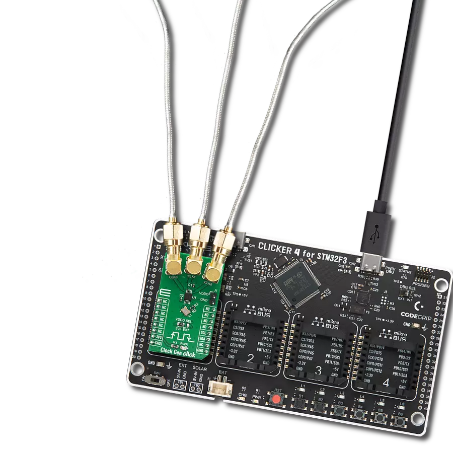
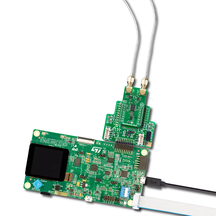
从选择您的开发板和Click板™开始。以Discovery kit with STM32L496AG MCU作为您的开发板开始。


软件支持
库描述
该库包含 Waveform 2 Click 驱动程序的 API。
关键功能:
waveform2_set_freq- 设置输出频率的功能waveform2_sine_output- 设置正弦波输出的功能waveform2_triangle_output- 设置三角波输出的功能
开源
代码示例
完整的应用程序代码和一个现成的项目可以通过NECTO Studio包管理器直接安装到NECTO Studio。 应用程序代码也可以在MIKROE的GitHub账户中找到。
/*!
 * @file main.c
 * @brief Waveform2 Click example
 *
 * # Description
 * This is an example that demonstrates the use of the Waveform 2 Click board.
 *
 * The demo application is composed of two sections :
 *
 * ## Application Init
 * Initialize the communication interface, preforming hardware reset, and configure the Click board.
 *
 * ## Application Task
 * Predefined characters are inputed from the serial port.
 * Depending on the character sent the signal frequency, waveform or amplitude
 * will be changed.
 *
 * - Command:
 * [ + ] - Increase frequency
 * [ - ] - Decrease frequency
 * [ t ] - Triangle-shaped signal
 * [ s ] - The signal in the form of a sinusoid
 *
 * - Additional Functions :
 * aprox_freq_calculation( float freqency ) - This function is used to calculate the aproximate
 * value that will be written to the frequency set register.
 *
 * @author Stefan Ilic
 *
 */

#include "board.h"
#include "log.h"
#include "waveform2.h"

static waveform2_t waveform2;
static log_t logger;

float value = 100000;
char demo_rx_buf[ 10 ];
char demo_tx_buf[ 10 ] = "MikroE";

/**
 * @brief Aproximate frequency calculation function.
 * @details This function is used to calculate the aproximate value that will be
 * written to the frequency set register..
 */
uint32_t aprox_freq_calculation ( float freqency );

void application_init ( void ) {
    log_cfg_t log_cfg;  /**< Logger config object. */
    waveform2_cfg_t waveform2_cfg;  /**< Click config object. */

    /**
     * Logger initialization.
     * Default baud rate: 115200
     * Default log level: LOG_LEVEL_DEBUG
     * @note If USB_UART_RX and USB_UART_TX
     * are defined as HAL_PIN_NC, you will
     * need to define them manually for log to work.
     * See @b LOG_MAP_USB_UART macro definition for detailed explanation.
     */
    LOG_MAP_USB_UART( log_cfg );
    log_init( &logger, &log_cfg );
    log_info( &logger, " Application Init " );

    // Click initialization.
    waveform2_cfg_setup( &waveform2_cfg );
    WAVEFORM2_MAP_MIKROBUS( waveform2_cfg, MIKROBUS_1 );
    err_t init_flag  = waveform2_init( &waveform2, &waveform2_cfg );
    if ( ( I2C_MASTER_ERROR == init_flag ) || ( SPI_MASTER_ERROR == init_flag ) ) {
        log_error( &logger, " Application Init Error. " );
        log_info( &logger, " Please, run program again... " );

        for ( ; ; );
    }
    waveform2_default_cfg ( &waveform2 );

    log_printf( &logger, "---- EEPROM test ----\r\n " );
    log_printf( &logger, ">> Write [MikroE] to address 0x0123\r\n " );
    waveform2_eeprom_write_string( &waveform2, 0x0123, demo_tx_buf, 6 );
    waveform2_eeprom_read_string ( &waveform2, 0x0123, demo_rx_buf, 6 );
    log_printf( &logger, ">> Read data: %s  from address 0x0123.... \r\n ", demo_rx_buf );
    Delay_ms ( 1000 );
    waveform2_hw_reset( &waveform2 );
    Delay_ms ( 1000 );

    log_printf( &logger, "---- Waveform set freqency ----\r\n" );
    int32_t freqency;
    freqency = aprox_freq_calculation( value );
    waveform2_set_freq( &waveform2, freqency );
    waveform2_triangle_output( &waveform2 );
    Delay_ms ( 1000 );
    log_info( &logger, " Application Task " );
}

void application_task ( void ) {
    char rx_data;
    uint32_t freq_data;

    if ( log_read( &logger, &rx_data, 1 ) ) {
        switch ( rx_data ) {
            case '+': {
                if ( value > 200000 ) {
                    value = 0;
                }
                value += 100000;
                freq_data = aprox_freq_calculation( value );
                waveform2_set_freq( &waveform2, freq_data );
                log_printf( &logger, ">> Increasing the frequency \r\n " );
                break;
            }

            case '-': {
                if ( value < 200000 ) {
                    value = 400000;
                }
                value -= 100000;
                freq_data = aprox_freq_calculation( value );
                waveform2_set_freq( &waveform2, freq_data );
                log_printf( &logger, ">> Decreasing the frequency \r\n " );
                break;
            }

            case 't': {
                waveform2_triangle_output( &waveform2 );
                log_printf( &logger, ">> Triangle output \r\n " );
                break;
            }

            case 's': {
                waveform2_sine_output( &waveform2 );
                log_printf( &logger,  ">> Sinusoid output \r\n " );
                break;
            }
        }
    }
}

int main ( void )
{
    /* Do not remove this line or clock might not be set correctly. */
    #ifdef PREINIT_SUPPORTED
    preinit();
    #endif

    application_init( );

    for ( ; ; )
    {
        application_task( );
    }

    return 0;
}

uint32_t aprox_freq_calculation ( float freqency ) {
    uint32_t calculation;
    float WAVEFORM_OSC_FREQ = 50000000.0;
    float WAVEFORM_CONSTANT = 268435456.0;

    calculation = freqency * ( WAVEFORM_CONSTANT / WAVEFORM_OSC_FREQ );

    return calculation;
}

// ------------------------------------------------------------------------ END
额外支持
资源
类别:时钟发生器