使用DRV8701和STM32F302VC迈入刷式直流电机控制的未来
平滑控制,最大潜力
已发布 7月 22, 2025
点击板
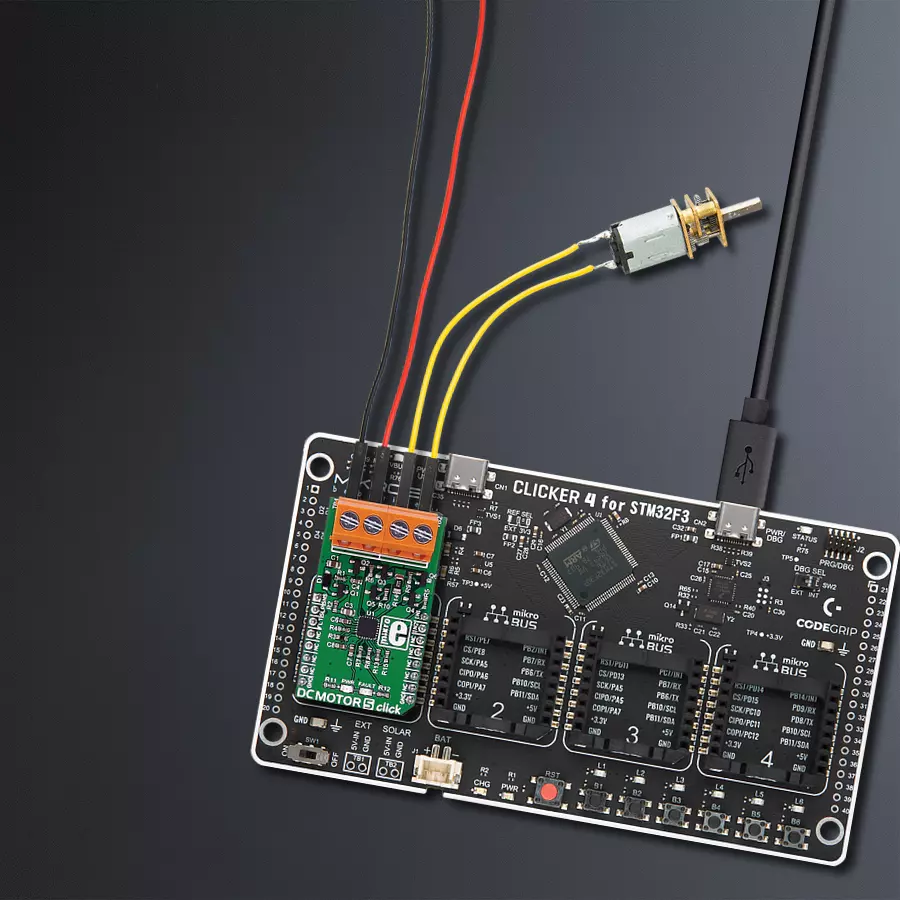
DC MOTOR 5 Click
开发板
CLICKER 4 for STM32F302VCT6
编译器
NECTO Studio
微控制器单元
STM32F302VC
通过我们尖端的“H桥”驱动解决方案,提升您的工程能力,实现定制化的电机控制。通过将这一可定制的创新技术纳入您的项目,今天就迈出迈向无与伦比的性能和效率的第一步。
A
A
硬件概览
它是如何工作的?
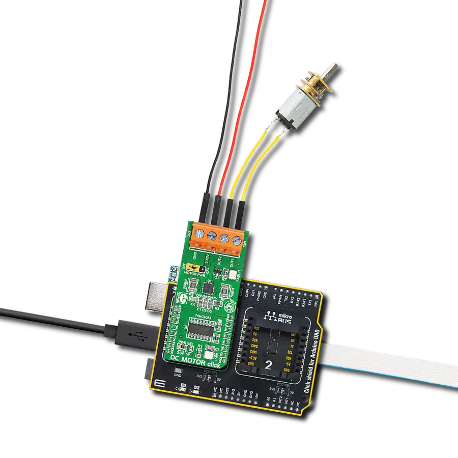
DC Motor 5 Click 基于德州仪器生产的 DRV8701 有刷直流电机门驱动器。此 Click 设计用于使用外部电源供电。它通过 mikroBUS™ 线上的 AN, RST, CS, PWM 和
INT 引脚与目标 MCU 通信。DRV8701 是一个 H 桥门驱动器(预驱动器或控制器)。该设备集成了 FET 门驱动器来控制四个外部 NMOS FETs。设备的供电电压范围为 5.9V 至 45V。
提供内部保护功能:欠压锁定、充电泵故障、过流关闭、短路保护、预驱动器故障和过温保护。电机的速度和方向可以通过两个 PWM 输入信号进行调整。

功能概述
开发板
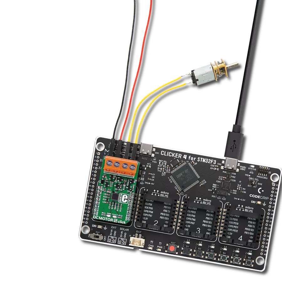
Clicker 4 for STM32F3 是一款紧凑型开发板,作为完整的解决方案而设计,可帮助用户快速构建具备独特功能的定制设备。该板搭载 STMicroelectronics 的 STM32F302VCT6 微控制器,配备四个 mikroBUS™ 插槽用于连接 Click boards™、完善的电源管理功能以及其他实用资源,是快速开发各类应用的理想平台。其核心 MCU STM32F302VCT6 基于高性能
Arm® Cortex®-M4 32 位处理器,运行频率高达 168MHz,处理能力强大,能够满足各种高复杂度任务的需求,使 Clicker 4 能灵活适应多种应用场景。除了两个 1x20 引脚排针外,板载最显著的连接特性是四个增强型 mikroBUS™ 插槽,支持接入数量庞大的 Click boards™ 生态系统,该生态每日持续扩展。Clicker 4 各功能区域标识清晰,界面直观简洁,极大
提升使用便捷性和开发效率。Clicker 4 的价值不仅在于加速原型开发与应用构建阶段,更在于其作为独立完整方案可直接集成至实际项目中,无需额外硬件修改。四角各设有直径 4.2mm(0.165")的安装孔,便于通过螺丝轻松固定。对于多数应用,只需配套一个外壳,即可将 Clicker 4 开发板转化为完整、实用且外观精美的定制系统。

微控制器概述
MCU卡片 / MCU

建筑
ARM Cortex-M4
MCU 内存 (KB)
256
硅供应商
STMicroelectronics
引脚数
100
RAM (字节)
40960
你完善了我!
配件
DC Gear Motor - 430RPM(3-6V)代表了电机和齿轮箱的一体化组合,其中增加齿轮会降低电机速度同时增加扭矩输出。这种齿轮电机拥有一个直齿轮箱,使其成为具有较低扭矩和速度要求的应用中的高可靠性解决方案。齿轮电机的最关键参数是速度、扭矩和效率,在本案例中,空载时为520RPM,最大效率时为430RPM,同时电流为60mA,扭矩为50g.cm。额定电压范围为3-6V,旋转方向为顺时针/逆时针,这款电机是机器人技术、医疗设备、电动门锁等许多最初由有刷直流电机执行的功能的优秀解决方案。

使用的MCU引脚
mikroBUS™映射器
“仔细看看!”
Click board™ 原理图

一步一步来
项目组装

从选择您的开发板和Click板™开始。以CLICKER 4 for STM32F302VCT6作为您的开发板开始。


实时跟踪您的结果
应用程序输出
1. 应用程序输出 - 在调试模式下,“应用程序输出”窗口支持实时数据监控,直接提供执行结果的可视化。请按照提供的教程正确配置环境,以确保数据正确显示。

2. UART 终端 - 使用UART Terminal通过USB to UART converter监视数据传输,实现Click board™与开发系统之间的直接通信。请根据项目需求配置波特率和其他串行设置,以确保正常运行。有关分步设置说明,请参考提供的教程。

3. Plot 输出 - Plot功能提供了一种强大的方式来可视化实时传感器数据,使趋势分析、调试和多个数据点的对比变得更加直观。要正确设置,请按照提供的教程,其中包含使用Plot功能显示Click board™读数的分步示例。在代码中使用Plot功能时,请使用以下函数:plot(insert_graph_name, variable_name);。这是一个通用格式,用户需要将“insert_graph_name”替换为实际图表名称,并将“variable_name”替换为要显示的参数。

软件支持
库描述
这个库包含了DC Motor 5 Click驱动的API。
关键功能:
dcmotor5_short_brake- 通过设置DC Motor 5 Click上的IN1(PWM)和IN2(INT)引脚来刹车引擎的功能dcmotor5_stop- 通过清除DC Motor 5 Click上的IN1(PWM)和IN2(INT)引脚来停止引擎的功能dcmotor5_enable- 通过清除DC Motor 5 Click上的SLEEP(RST)引脚来禁用引擎的功能
开源
代码示例
完整的应用程序代码和一个现成的项目可以通过NECTO Studio包管理器直接安装到NECTO Studio。 应用程序代码也可以在MIKROE的GitHub账户中找到。
/*!
 * @file main.c
 * @brief DCMotor5 Click example
 *
 * # Description
 * This library contains API for the DC Motor 5 Click driver.
 * This application enables usage of brushed DC motor 5 gate driver.
 *
 * The demo application is composed of two sections :
 *
 * ## Application Init
 * Initializes GPIO, PWM and logger and enables the Click board.
 *
 * ## Application Task
 * This is a example which demonstrates the use of DC Motor 5 Click board.
 * DC Motor 5 Click controls DC Motor speed via PWM interface.
 * It shows moving in the both directions from slow to fast speed
 * and from fast to slow speed.
 * Results are being sent to the Usart Terminal where you can track their changes.
 *
 * @author Nikola Peric
 *
 */

#include "board.h"
#include "log.h"
#include "dcmotor5.h"

// ------------------------------------------------------------------ VARIABLES

static dcmotor5_t dcmotor5;
static log_t logger;
uint8_t dcmotor_direction = 1;

// ------------------------------------------------------ APPLICATION FUNCTIONS

void application_init ( void )
{
    log_cfg_t log_cfg;
    dcmotor5_cfg_t cfg;

    /**
     * Logger initialization.
     * Default baud rate: 115200
     * Default log level: LOG_LEVEL_DEBUG
     * @note If USB_UART_RX and USB_UART_TX
     * are defined as HAL_PIN_NC, you will
     * need to define them manually for log to work.
     * See @b LOG_MAP_USB_UART macro definition for detailed explanation.
     */
    LOG_MAP_USB_UART( log_cfg );
    log_init( &logger, &log_cfg );
    log_info( &logger, "---- Application Init ----" );

    //  Click initialization.

    dcmotor5_cfg_setup( &cfg );
    DCMOTOR5_MAP_MIKROBUS( cfg, MIKROBUS_1 );
    dcmotor5_init( &dcmotor5, &cfg );

    log_printf( &logger, " Initialization  PWM \r\n" );

    dcmotor5_pwm_start( &dcmotor5 );
    dcmotor5_enable ( &dcmotor5 );
    Delay_ms ( 500 );
    log_printf( &logger, "---------------------\r\n" );
    log_info( &logger, "---- Application Task ----" );
}


void application_task ( )
{
    static float duty;
    static uint8_t n_cnt;


    dcmotor5_clockwise ( &dcmotor5 );
    log_printf( &logger, "\r\n> CLOCKWISE <\r\n" );
    dcmotor5_enable ( &dcmotor5 );

    for ( n_cnt = 10; n_cnt > 0; n_cnt--  )
    {
        duty = ( float ) n_cnt ;
        duty /= 10;
        log_printf( &logger, " >" );
        dcmotor5_set_duty_cycle( &dcmotor5, duty );
        Delay_ms ( 500 );
    }
    for ( n_cnt = 1; n_cnt <= 10; n_cnt++ )
    {
        duty = ( float ) n_cnt ;
        duty /= 10;
        log_printf( &logger, " <" );
        dcmotor5_set_duty_cycle( &dcmotor5,  duty );
        Delay_ms ( 500 );
    }

    log_printf( &logger, "\r\n * Pull break *\r\n" );
    dcmotor5_short_brake( &dcmotor5 );
    Delay_ms ( 1000 );

    dcmotor5_counter_clockwise ( &dcmotor5 );
    log_printf( &logger, "\r\n> COUNTER CLOCKWISE <\r\n" );

    for ( n_cnt = 1; n_cnt <= 10; n_cnt++  )
    {
        duty = ( float ) n_cnt ;
        duty /= 10;
        dcmotor5_set_duty_cycle( &dcmotor5, duty );
        log_printf( &logger, " >" );
        Delay_ms ( 500 );
    }
    for ( n_cnt = 10; n_cnt > 0; n_cnt-- )
    {
        duty = ( float ) n_cnt ;
        duty /= 10;
        dcmotor5_set_duty_cycle( &dcmotor5,  duty );
        log_printf( &logger, " <" );
        Delay_ms ( 500 );
    }

}

int main ( void )
{
    /* Do not remove this line or clock might not be set correctly. */
    #ifdef PREINIT_SUPPORTED
    preinit();
    #endif

    application_init( );

    for ( ; ; )
    {
        application_task( );
    }

    return 0;
}

// ------------------------------------------------------------------------ END
额外支持
资源
类别:有刷