使用G6D1AASIDC5和STM32L496AG控制任何高功率应用
通用继电器,最大切换电压为125VAC/60VDC
已发布 7月 22, 2025
点击板
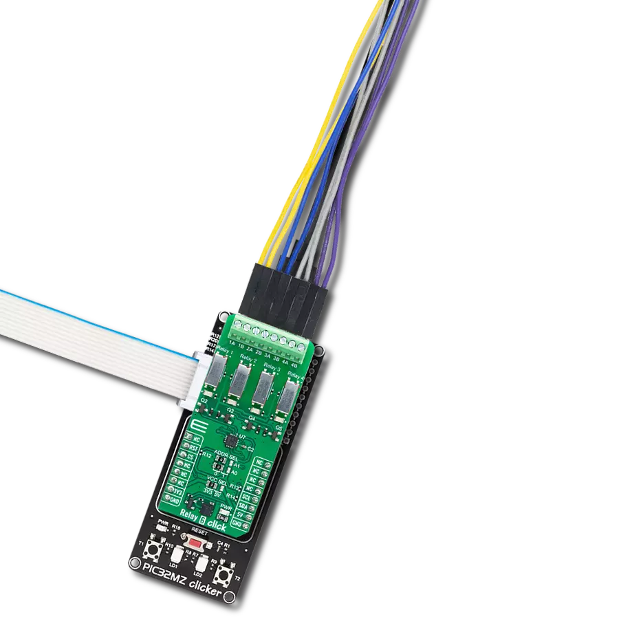
RELAY Click
开发板
Discovery kit with STM32L496AG MCU
编译器
NECTO Studio
微控制器单元
STM32L496AG
轻松创建一个遥控开关,用于在您的项目中开启和关闭诸如灯光或电机等设备。
A
A
硬件概览
它是如何工作的?
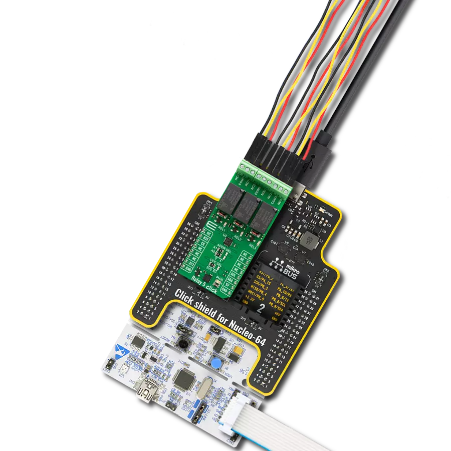
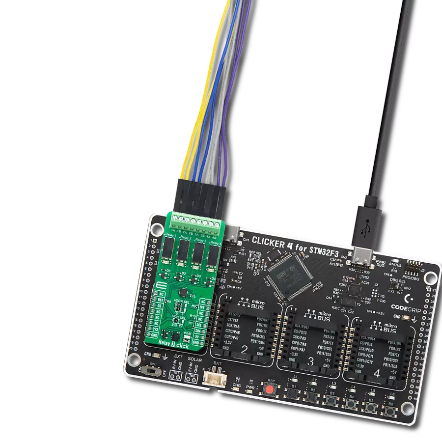
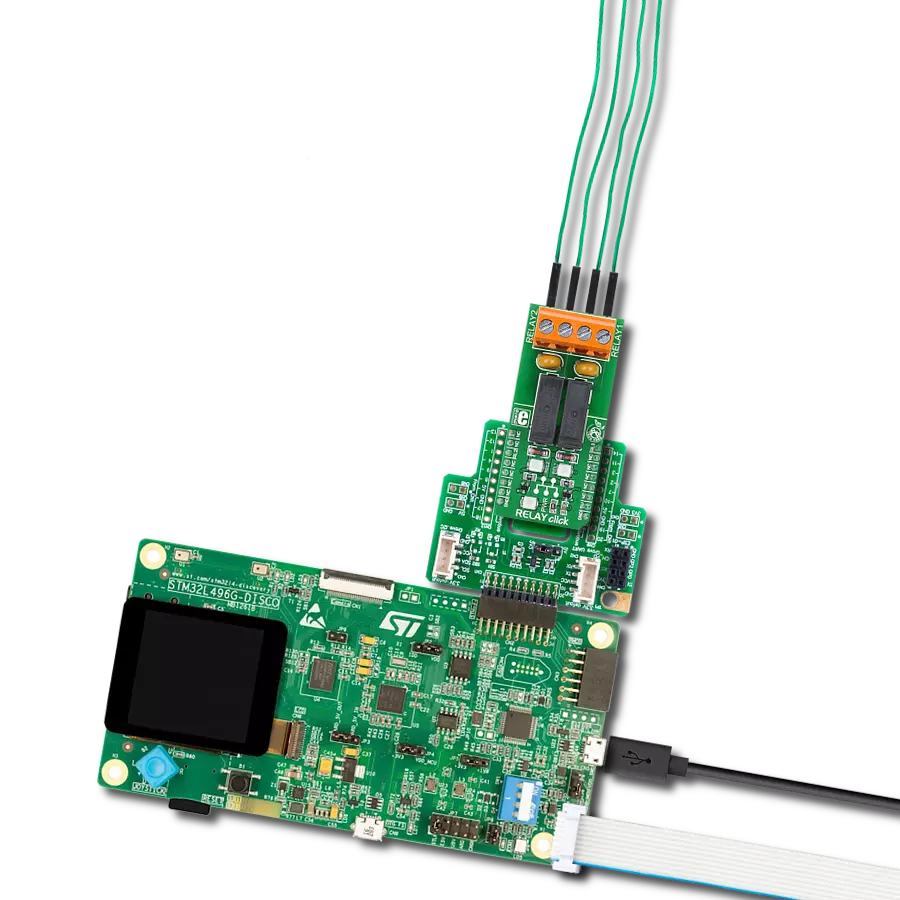
RELAY Click 基于两个 OMRON 的细长微型继电器 G6D1AASIDC5。尽管体积小,G6D-1A-ASI DC5 继电器可以承受高达 5A 和 220V AC/30V DC 的电流和电压。在 30V DC 和 2A 的条件下,它能承受高达 300,000 次的操作。这种继电器只有单极 - 当线圈被激活时,它将吸引内部切换元件并闭合电路,类似于 开关。这些继电器的设计使得相对较低的电流和电压
就可以轻松激活它们的线圈。对于在 5V 下操作的 G6D-1A-ASI DC5 继电器,线圈电流为 40mA。这使它们非常适合由 MCU 激活。RELAY Click 使用 GPIO 引脚 RL1 和 RL2 由主 MCU 控制。由于 RELAY Click 使用 NPN RET 和电阻,因此主 MCU 免受驱动继电器线圈的电流尖峰的影响。此外,每个继电器都有一个 LED,每个 LED 颜色不同,代表继
电器的状态。这个 Click board™ 只能在 5V 逻辑电压水平下操作。在使用具有不同逻辑电平的 MCU 之前,必须执行适当的逻辑电压水平转换。此外,它还配备了包含功能和示例代码的库,可用作进一步开发的参考。

功能概述
开发板
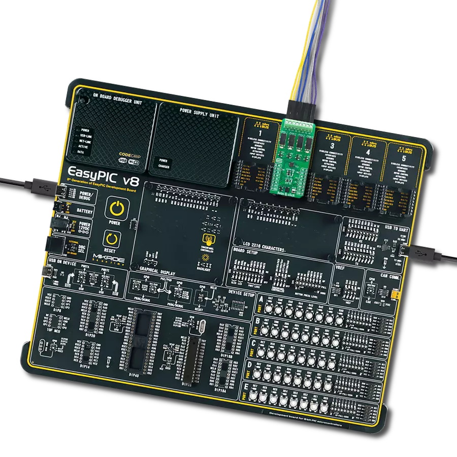
32L496GDISCOVERY Discovery 套件是一款功能全面的演示和开发平台,专为搭载 Arm® Cortex®-M4 内核的 STM32L496AG 微控制器设计。该套件适用于需要在高性能、先进图形处理和超低功耗之间取得平衡的应用,支持无缝原型开发,适用于各种嵌入式解决方案。STM32L496AG 采用创新的节能架构,集成
了扩展 RAM 和 Chrom-ART 图形加速器,在提升图形性能的同时保持低功耗,使其特别适用于音频处理、图形用户界面和实时数据采集等对能效要求较高的应用。为了简化开发流程,该开发板配备了板载 ST-LINK/V2-1 调试器/编程器,提供即插即用的调试和编程体验,使用户无需额外硬件即可轻松加载、调
试和测试应用程序。凭借低功耗特性、增强的内存能力以及内置调试工具,32L496GDISCOVERY 套件是开发先进嵌入式系统、实现高效能解决方案的理想选择。

微控制器概述
MCU卡片 / MCU

建筑
ARM Cortex-M4
MCU 内存 (KB)
1024
硅供应商
STMicroelectronics
引脚数
169
RAM (字节)
327680
使用的MCU引脚
mikroBUS™映射器
“仔细看看!”
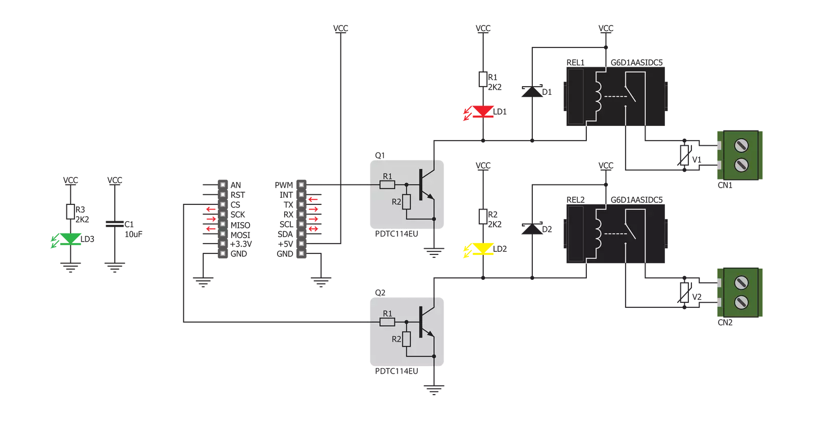
Click board™ 原理图
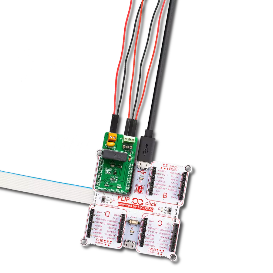
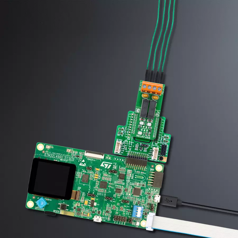
一步一步来
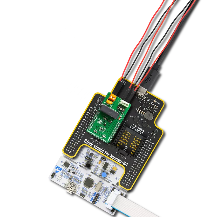
项目组装

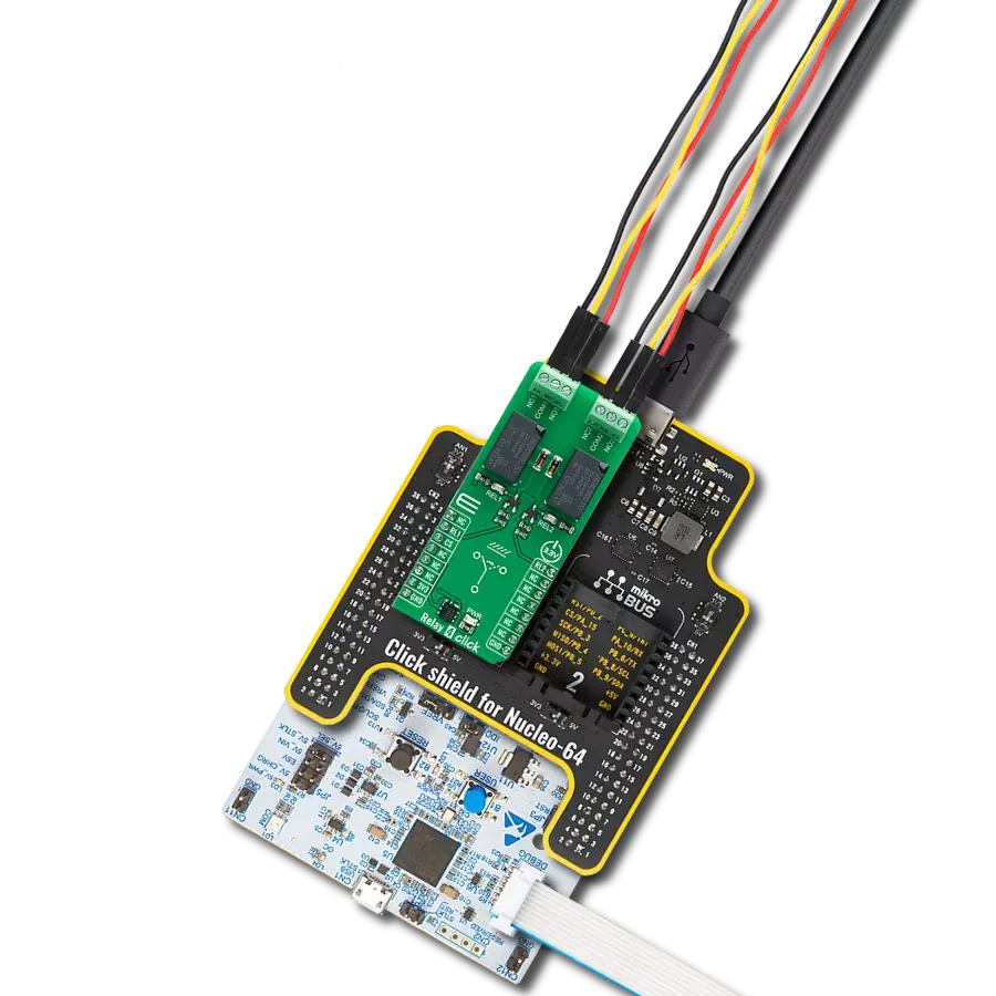
从选择您的开发板和Click板™开始。以Discovery kit with STM32L496AG MCU作为您的开发板开始。


软件支持
库描述
此库包含 RELAY Click 驱动程序的 API。
关键功能:
relay_set_state- 设置继电器状态。
开源
代码示例
完整的应用程序代码和一个现成的项目可以通过NECTO Studio包管理器直接安装到NECTO Studio。 应用程序代码也可以在MIKROE的GitHub账户中找到。
/*!
 * \file
 * \brief Relay Click example
 *
 * # Description
 * Demo application is used to shows basic controls Relay Click
 *
 * The demo application is composed of two sections :
 *
 * ## Application Init
 * Configuring Clicks and log objects.
 * Settings the Click in the default configuration.
 *
 * ## Application Task
 * Alternately sets relays to ON-OFF state...
 *
 * \author Katarina Perendic
 *
 */
// ------------------------------------------------------------------- INCLUDES

#include "board.h"
#include "log.h"
#include "relay.h"

// ------------------------------------------------------------------ VARIABLES

static relay_t relay;
static log_t logger;

// ------------------------------------------------------ APPLICATION FUNCTIONS

void application_init ( void )
{
    log_cfg_t log_cfg;
    relay_cfg_t cfg;

    /**
     * Logger initialization.
     * Default baud rate: 115200
     * Default log level: LOG_LEVEL_DEBUG
     * @note If USB_UART_RX and USB_UART_TX
     * are defined as HAL_PIN_NC, you will
     * need to define them manually for log to work.
     * See @b LOG_MAP_USB_UART macro definition for detailed explanation.
     */
    LOG_MAP_USB_UART( log_cfg );
    log_init( &logger, &log_cfg );
    log_info(&logger, "---- Application Init ----");

    //  Click initialization.

    relay_cfg_setup( &cfg );
    RELAY_MAP_MIKROBUS( cfg, MIKROBUS_1 );
    relay_init( &relay, &cfg );

    relay_default_cfg ( &relay );
    Delay_ms ( 1000 );
    Delay_ms ( 500 );
}

void application_task ( void )
{
    uint8_t cnt;

    //  Task implementation.

    for ( cnt = 1; cnt <= 2; cnt++)
    {
        log_info( &logger, "*** Relay %d state is ON \r\n", (uint16_t)cnt);
        relay_set_state( &relay, cnt, RELAY_STATE_ON );
        Delay_ms ( 1000 );
        log_info( &logger, "*** Relay %d state is OFF \r\n", (uint16_t)cnt);
        relay_set_state( &relay, cnt, RELAY_STATE_OFF );
        Delay_ms ( 200 );
    }
}

int main ( void )
{
    /* Do not remove this line or clock might not be set correctly. */
    #ifdef PREINIT_SUPPORTED
    preinit();
    #endif

    application_init( );

    for ( ; ; )
    {
        application_task( );
    }

    return 0;
}


// ------------------------------------------------------------------------ END
额外支持
资源
类别:继电器