使用TC78H653FTG和PIC32MZ1024EFH064释放您的直流有刷电机的潜力
平滑移动,锐利转弯

已发布 6月 26, 2024
点击板
DC Motor 19 Click
开发板
PIC32MZ clicker
编译器
NECTO Studio
微控制器单元
PIC32MZ1024EFH064
确保机器人和自动化系统的平稳可靠运行。
A
A
硬件概览
它是如何工作的?
DC Motor 19 Click基于TC78H653FTG,这是东芝半导体的一款用于一个或两个有刷直流电机或一个步进电机的双H桥驱动器。TC78H653FTG内部集成了H桥电路的MOSFET,使用低导通电阻的DMOS元件(在5V电源和激活的大模式下典型值为0.11Ω)。它具有宽工作电压范围,输出电流能力为4A(DC),以及包括电机相关功能(前进、后退、制动、停止)、电流控制和内置检测电路(过电流、过热、低/高电压)在内的控制功能。如产品描述所述,DC Motor 19 Click通过多个GPIO引脚与MCU通信。此外,该Click板™具有一个标记为SBY的待机引脚,路由到mikroBUS™插座的CS引脚,
用于通过切换引脚进入待机模式。当SBY引脚为低电平时,TC78H653FTG停止向逻辑电路供电,由于IC中的所有电路都配置为CMOS/DMOS元件,待机电流显著减少,此模式下的电流消耗为典型值0μA。要打开TC78H653FTG的内部MOSFET,需要通过逻辑电平切换,输入控制引脚:IN1、IN2、IN3和IN4引脚,分别路由到mikroBUS™插座的RST、AN、PWM和INT引脚。因此,可以根据输入控制信号的状态选择前进/后退/制动/停止旋转方向模式,同时可以通过标记为MODE和LARGE的板载开关以及控制信号选择电机运行和电流模式。在激活大模式时,IN1和IN2引脚控制该模式,而电机控
制引脚A+和A-连接为OUT+,B-和B+引脚连接为OUT-。有关电机模式选择的更多信息,请参见随附的datasheet。DC Motor 19支持TC78H653FTG的外部电源,可以连接到标记为VM的输入端子,电压范围应在1.8V到7.5V之间,同时可以将直流电机线圈连接到标记为B+、B-、A-和A+的端子上。此Click板™可以通过VCC SEL跳线选择3.3V或5V逻辑电压电平,从而使3.3V和5V能力的MCU能够正确使用通信线路。该Click板™配备了一个包含易于使用的函数和示例代码的库,可作为进一步开发的参考。

功能概述
开发板
PIC32MZ Clicker 是一款紧凑型入门开发板,它将 Click 板™的灵活性带给您喜爱的微控制器,使其成为实现您想法的完美入门套件。它配备了一款板载 32 位带有浮点单元的 Microchip PIC32MZ 微控制器,一个 USB 连接器,LED 指示灯,按钮,一个 mikroProg 连接器,以及一个用于与外部电子设备接口的头部。得益于其紧凑的设计和清晰易识别的丝网标记,它提供了流畅且沉浸式的工作体验,允许在任
何情况下、任何地方都能访问。PIC32MZ Clicker 开 发套件的每个部分都包含了使同一板块运行最高效的必要组件。除了可以选择 PIC32MZ Clicker 的编程方式,使用 USB HID mikroBootloader 或通过外部 mikroProg 连接器为 PIC,dsPIC 或 PIC32 编程外,Clicker 板还包括一个干净且调节过的开发套件电源供应模块。USB Micro-B 连接可以提供多达 500mA 的电流,这足以操作所有板载和附加模块。所有
mikroBUS™ 本身支持的通信方法都在这块板上,包 括已经建立良好的 mikroBUS™ 插槽、重置按钮以及若干按钮和 LED 指示灯。PIC32MZ Clicker 是 Mikroe 生态系统的一个组成部分,允许您在几分钟内创建新的应用程序。它由 Mikroe 软件工具原生支持,得益于大量不同的 Click 板™(超过一千块板),其数量每天都在增长,它涵盖了原型制作的许多方面。

微控制器概述
MCU卡片 / MCU

建筑
PIC32
MCU 内存 (KB)
1024
硅供应商
Microchip
引脚数
64
RAM (字节)
524288
你完善了我!
配件
直流齿轮电机 - 430RPM (3-6V) 代表了电机和齿轮箱的一体化组合,通过添加齿轮可以降低电机速度,同时增加扭矩输出。该齿轮电机配备直齿齿轮箱,是低扭矩和低速度要求应用的高度可靠解决方案。对于齿轮电机来说,最关键的参数是速度、扭矩和效率,在本例中,无负载速度为520RPM,最大效率时速度为430RPM,电流为60mA,扭矩为50g.cm。额定工作电压范围为3-6V,支持顺时针和逆时针旋转方向,这款电机是许多最初由有刷直流电机执行的功能的绝佳解决方案,广泛应用于机器人、医疗设备、电动门锁等。

使用的MCU引脚
mikroBUS™映射器
“仔细看看!”
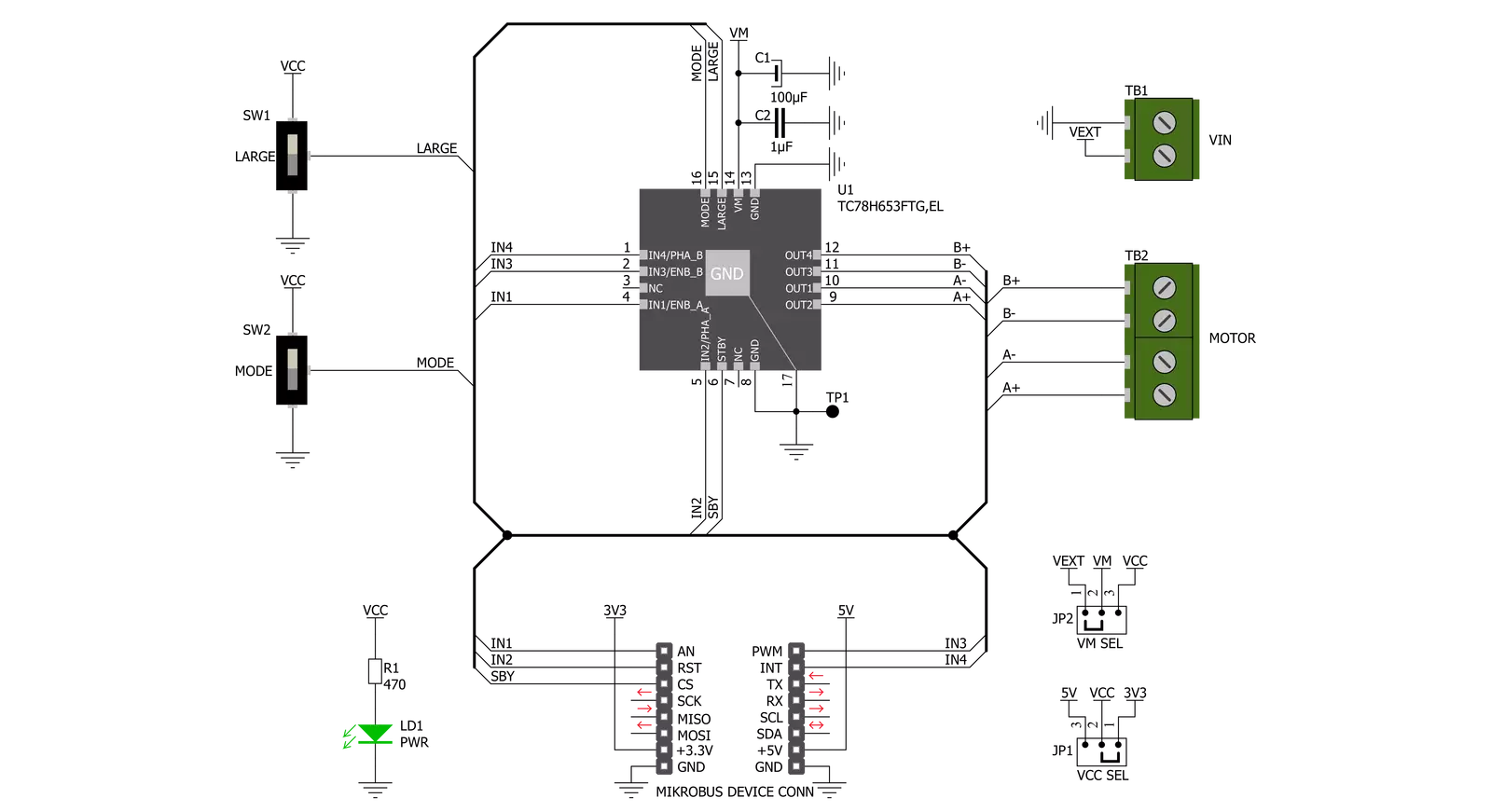
Click board™ 原理图
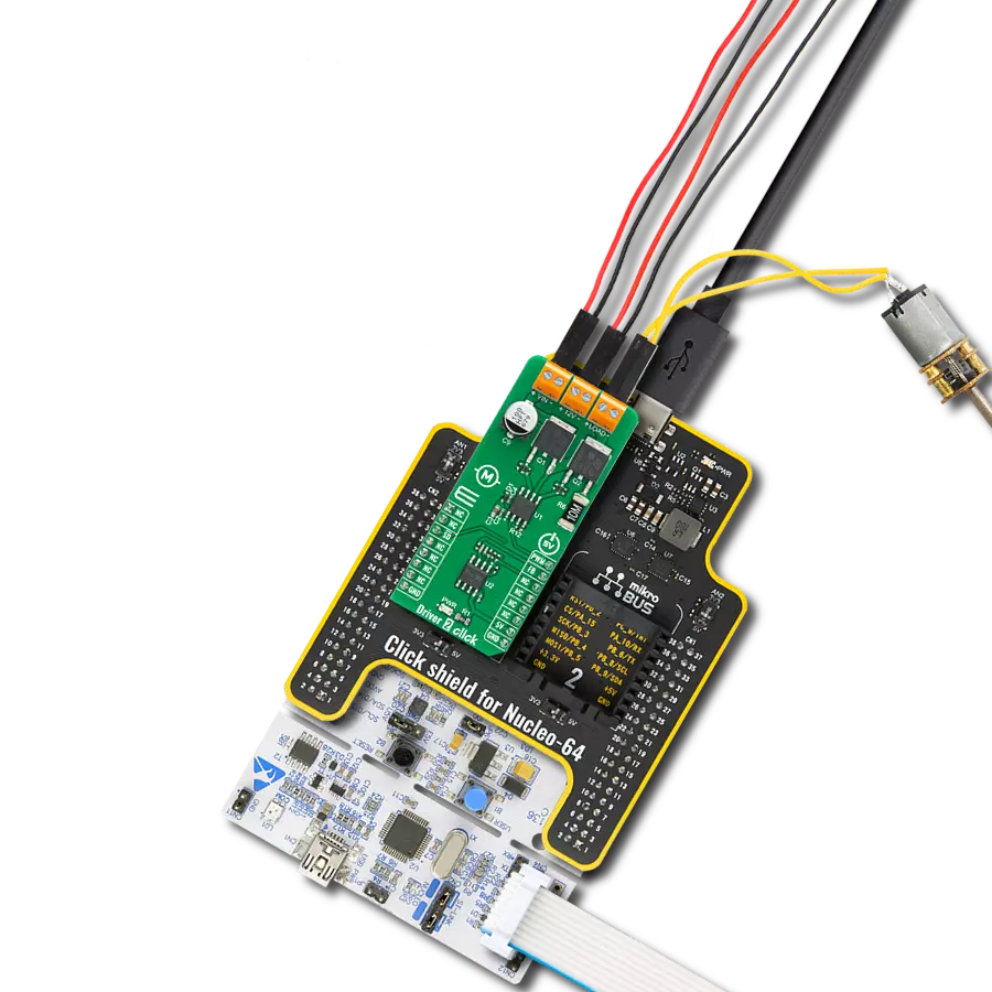
一步一步来
项目组装

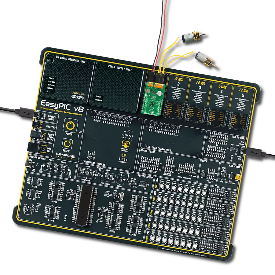
从选择您的开发板和Click板™开始。以PIC32MZ clicker作为您的开发板开始。


实时跟踪您的结果
应用程序输出
1. 应用程序输出 - 在调试模式下,“应用程序输出”窗口支持实时数据监控,直接提供执行结果的可视化。请按照提供的教程正确配置环境,以确保数据正确显示。

2. UART 终端 - 使用UART Terminal通过USB to UART converter监视数据传输,实现Click board™与开发系统之间的直接通信。请根据项目需求配置波特率和其他串行设置,以确保正常运行。有关分步设置说明,请参考提供的教程。

3. Plot 输出 - Plot功能提供了一种强大的方式来可视化实时传感器数据,使趋势分析、调试和多个数据点的对比变得更加直观。要正确设置,请按照提供的教程,其中包含使用Plot功能显示Click board™读数的分步示例。在代码中使用Plot功能时,请使用以下函数:plot(insert_graph_name, variable_name);。这是一个通用格式,用户需要将“insert_graph_name”替换为实际图表名称,并将“variable_name”替换为要显示的参数。

软件支持
库描述
该库包含 DC Motor 19 Click 驱动程序的 API。
关键功能:
dcmotor19_drive_motor- 该功能以指定的速度驱动电机,并在time_ms指定的时间内运行。必须使用dcmotor19_set_channel_mode函数预先选择电机通道和模式。dcmotor19_set_channel_mode- 该功能设置将由dcmotor19_drive_motor函数使用的活动通道和模式。dcmotor19_disable_standby_mode- 该功能禁用待机模式。
开源
代码示例
完整的应用程序代码和一个现成的项目可以通过NECTO Studio包管理器直接安装到NECTO Studio。 应用程序代码也可以在MIKROE的GitHub账户中找到。
/*!
 * @file main.c
 * @brief DC Motor 19 Click Example.
 *
 * # Description
 * This example demonstrates the use of DC Motor 19 click board by driving the motors
 * in both direction in the span of 14 seconds.
 *
 * The demo application is composed of two sections :
 *
 * ## Application Init
 * Initializes the driver and enables the click by disabling the standby mode.
 *
 * ## Application Task
 * Drives the motors in the forward direction for 5 seconds, then pulls brake for 2 seconds,
 * and after that drives them in the reverse direction for 5 seconds, and finally,
 * stops driving for 2 seconds which basically disconnects the motors.
 * Each step will be logged on the USB UART where you can track the program flow.
 *
 * @author Stefan Filipovic
 *
 */

#include "board.h"
#include "log.h"
#include "dcmotor19.h"

static dcmotor19_t dcmotor19;   /**< DC Motor 19 Click driver object. */
static log_t logger;            /**< Logger object. */

void application_init ( void )
{
    log_cfg_t log_cfg;              /**< Logger config object. */
    dcmotor19_cfg_t dcmotor19_cfg;  /**< Click config object. */

    /**
     * Logger initialization.
     * Default baud rate: 115200
     * Default log level: LOG_LEVEL_DEBUG
     * @note If USB_UART_RX and USB_UART_TX
     * are defined as HAL_PIN_NC, you will
     * need to define them manually for log to work.
     * See @b LOG_MAP_USB_UART macro definition for detailed explanation.
     */
    LOG_MAP_USB_UART( log_cfg );
    log_init( &logger, &log_cfg );
    log_info( &logger, " Application Init " );

    // Click initialization.
    dcmotor19_cfg_setup( &dcmotor19_cfg );
    DCMOTOR19_MAP_MIKROBUS( dcmotor19_cfg, MIKROBUS_1 );
    if ( DIGITAL_OUT_UNSUPPORTED_PIN == dcmotor19_init( &dcmotor19, &dcmotor19_cfg ) )
    {
        log_error( &logger, " Communication init." );
        for ( ; ; );
    }
    dcmotor19_disable_standby_mode ( &dcmotor19 );
    log_info( &logger, " Application Task " );
}
void application_task ( void )
{
    log_printf ( &logger, " Driving motors forward...\r\n" );
    dcmotor19_set_channel_mode ( &dcmotor19, DCMOTOR19_CHANNEL_1 | DCMOTOR19_CHANNEL_2, DCMOTOR19_MODE_FORWARD );
    dcmotor19_drive_motor ( &dcmotor19, DCMOTOR19_SPEED_DEFAULT, 5000 );
    log_printf ( &logger, " Pull brake!\r\n" );
    dcmotor19_set_channel_mode ( &dcmotor19, DCMOTOR19_CHANNEL_1 | DCMOTOR19_CHANNEL_2, DCMOTOR19_MODE_SHORT_BRAKE );
    Delay_ms ( 1000 );
    Delay_ms ( 1000 );
    log_printf ( &logger, " Driving motors in reverse...\r\n" );
    dcmotor19_set_channel_mode ( &dcmotor19, DCMOTOR19_CHANNEL_1 | DCMOTOR19_CHANNEL_2, DCMOTOR19_MODE_REVERSE );
    dcmotor19_drive_motor ( &dcmotor19, DCMOTOR19_SPEED_DEFAULT, 5000 );
    log_printf ( &logger, " Stop driving!\r\n\n" );
    dcmotor19_set_channel_mode ( &dcmotor19, DCMOTOR19_CHANNEL_1 | DCMOTOR19_CHANNEL_2, DCMOTOR19_MODE_STOP );
    Delay_ms ( 1000 );
    Delay_ms ( 1000 );
}

int main ( void )
{
    /* Do not remove this line or clock might not be set correctly. */
    #ifdef PREINIT_SUPPORTED
    preinit();
    #endif

    application_init( );

    for ( ; ; )
    {
        application_task( );
    }

    return 0;
}

// ------------------------------------------------------------------------ END