使用TMC7300和STM32G474RE使您的有刷直流电机稳定运行
电机控制 - 尽在掌握!

已发布 11月 08, 2024
点击板
DC Motor 22 Click
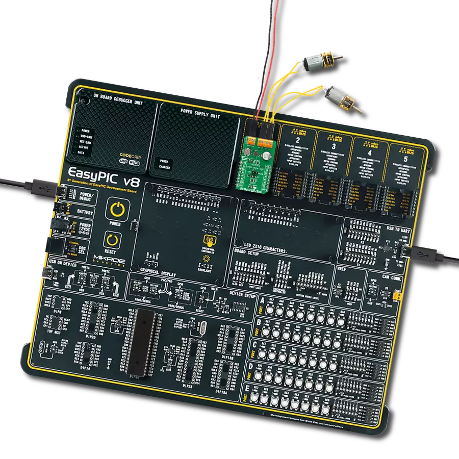
开发板
Nucleo 64 with STM32G474RE MCU
编译器
NECTO Studio
微控制器单元
STM32G474RE
确保高效且可靠的 BDC 运行。
A
A
硬件概览
它是如何工作的?
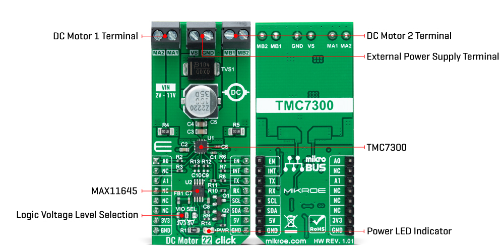
DC Motor 22 Click 基于 Analog Devices 的 TMC7300,这是一款优化用于 DC 电机控制的低压驱动器。TMC7300 采用集成的功率 MOSFET 和完整的集成 DC 电机控制逻辑,实现速度控制、扭矩限制和扭矩控制操作,具有高功率密度。其额定工作电压范围为 2V 至 11V,覆盖广泛的嵌入式应用,每个电机端子可提供高达 2A(峰值 2.4A)的电流。该先进驱动器确保高效且可靠的运行,提供具有成本效益和高度竞争力的解决方案。如前所述,TMC7300 通过简单的 UART 控制进行操作,默认波特率为 115200bps 数据传输,允许操
作两个 DC 电机或一个双电流的电机。电机由内部 PWM 发生器操作,所需的占空比通过 UART 接口编程。PWM 像专用电压源一样为电机提供电压,通过设置每个电机的 PWM 电压,提供对电机速度和方向的完全控制。该接口还通过设置一个共同的电流限制来控制两个电机的扭矩限制,允许在加速或电机被堵住时安全地避免过载。此外,该 Click board™ 还具有 A 和 B 通道的电流感应功能。基于填充的感应电阻 R4 和 R5 以及 MAX11645 模数转换器,用户可以通过 I2C 接口获取通道的当前值信息。此外,它还使用了多个
mikroBUS™ 引脚。通过 mikroBUS™ 插座的 EN 引脚提供的启用功能提供了一个开关操作,用于开启/关闭电力传输到连接的负载,而 A0 和 A1 引脚选择 UART 接口地址。它还具有一整套诊断和保护功能,支持稳健和可靠的操作,如接地短路保护、电源短路保护和通过 mikroBUS™ 插座的 INT 引脚报告的欠压检测。此 Click board™ 可通过 VIO SEL 跳线选择 3.3V 或 5V 逻辑电压水平。这允许 3.3V 和 5V 的 MCU 正确使用通信线路。然而,该 Click board™ 配备了包含易于使用的函数和示例代码的库,可作为进一步开发的参考。
功能概述
开发板
Nucleo-64 搭载 STM32G474R MCU 提供了一种经济高效且灵活的平台,供开发者探索新想法并原型设计他们的项目。该板利用 STM32 微控制器的多功能性,使用户能够为他们的项目选择最佳的性能与功耗平衡。它配备了 LQFP64 封装的 STM32 微控制器,并包含了如用户 LED(同时作为 ARDUINO® 信号)、用户和复位按钮,以及 32.768kHz 晶体振荡器用于精确的计时操作等基本组件。Nucleo-64 板设计考虑到扩展性和灵活性,它特有的 ARDUINO® Uno
V3 扩展连接器和 ST morpho 扩展引脚头,提供了对 STM32 I/O 的完全访问,以实现全面的项目整合。电源供应选项灵活,支持 ST-LINK USB VBUS 或外部电源,确保在各种开发环境中的适应性。该板还配备了一个具有 USB 重枚举功能的板载 ST-LINK 调试器/编程器,简化了编程和调试过程。此外,该板设计旨在简化高级开发,它的外部 SMPS 为 Vcore 逻辑供电提供高效支持,支持 USB 设备全速或 USB SNK/UFP 全速,并内置加密功能,提升了项目的功效
和安全性。通过外部 SMPS 实验的专用连接器、 用于 ST-LINK 的 USB 连接器以及 MIPI® 调试连接器,提供了更多的硬件接口和实验可能性。开发者将通过 STM32Cube MCU Package 提供的全面免费软件库和示例得到广泛支持。这些,加上与多种集成开发环境(IDE)的兼容性,包括 IAR Embedded Workbench®、MDK-ARM 和 STM32CubeIDE,确保了流畅且高效的开发体验,使用户能够充分利用 Nucleo-64 板在他们的项目中的能力。

微控制器概述
MCU卡片 / MCU

建筑
ARM Cortex-M4
MCU 内存 (KB)
512
硅供应商
STMicroelectronics
引脚数
64
RAM (字节)
128k
你完善了我!
配件
Click Shield for Nucleo-64 配备了两个专有的 mikroBUS™ 插座,使得所有的 Click board™ 设备都可以轻松地与 STM32 Nucleo-64 开发板连接。这样,Mikroe 允许其用户从不断增长的 Click boards™ 范围中添加任何功能,如 WiFi、GSM、GPS、蓝牙、ZigBee、环境传感器、LED、语音识别、电机控制、运动传感器等。您可以使用超过 1537 个 Click boards™,这些 Click boards™ 可以堆叠和集成。STM32 Nucleo-64 开发板基于 64 引脚封装的微控制器,采用 32 位 MCU,配备 ARM Cortex M4 处理器,运行速度为 84MHz,具有 512Kb Flash 和 96KB SRAM,分为两个区域,顶部区域代表 ST-Link/V2 调试器和编程器,而底部区域是一个实际的开发板。通过 USB 连接方便地控制和供电这些板子,以便直接对 Nucleo-64 开发板进行编程和高效调试,其中还需要额外的 USB 线连接到板子上的 USB 迷你接口。大多数 STM32 微控制器引脚都连接到了板子左右边缘的 IO 引脚上,然后连接到两个现有的 mikroBUS™ 插座上。该 Click Shield 还有几个开关,用于选择 mikroBUS™ 插座上模拟信号的逻辑电平和 mikroBUS™ 插座本身的逻辑电压电平。此外,用户还可以通过现有的双向电平转换器,使用任何 Click board™,无论 Click board™ 是否在 3.3V 或 5V 逻辑电压电平下运行。一旦将 STM32 Nucleo-64 开发板与我们的 Click Shield for Nucleo-64 连接,您就可以访问数百个工作于 3.3V 或 5V 逻辑电压电平的 Click boards™。

DC 齿轮电机 - 430RPM (3-6V) 是电机和齿轮箱的全合一组合,其中齿轮的添加降低了电机速度,同时增加了扭矩输出。该齿轮电机具有一个齿轮传动箱,使其成为低扭矩和速度要求应用的高可靠解决方案。齿轮电机的最关键参数是速度、扭矩和效率,在这种情况下,空载速度为 520RPM,最大效率下为 430RPM,电流为 60mA,扭矩为 50g.cm。额定工作电压范围为 3-6V,支持顺时针/逆时针旋转方向,该电机是机器人、医疗设备、电动门锁等领域许多最初由有刷直流电机执行功能的出色解决方案。

使用的MCU引脚
mikroBUS™映射器
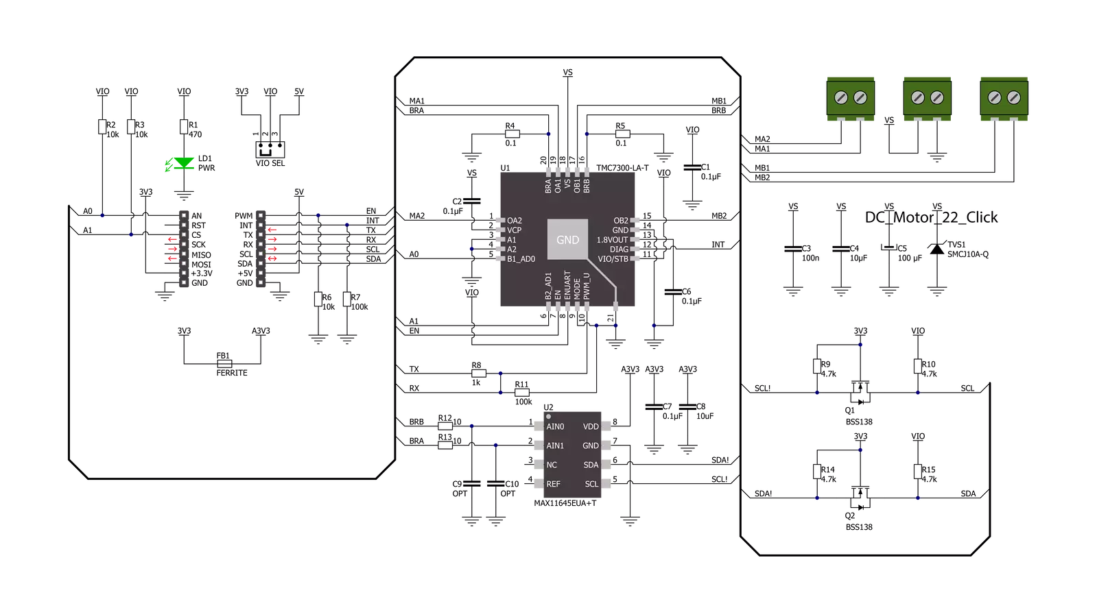
“仔细看看!”
Click board™ 原理图
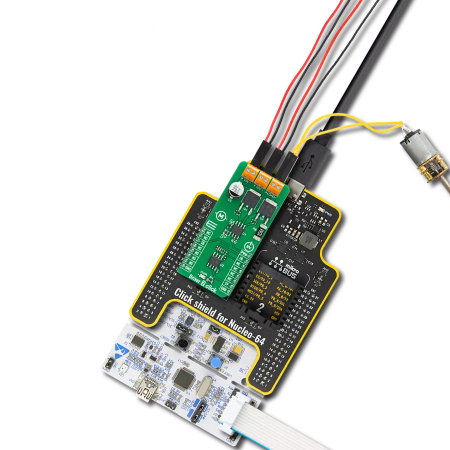
一步一步来
项目组装
从选择您的开发板和Click板™开始。以Nucleo 64 with STM32G474RE MCU作为您的开发板开始。


实时跟踪您的结果
应用程序输出
1. 应用程序输出 - 在调试模式下,“应用程序输出”窗口支持实时数据监控,直接提供执行结果的可视化。请按照提供的教程正确配置环境,以确保数据正确显示。

2. UART 终端 - 使用UART Terminal通过USB to UART converter监视数据传输,实现Click board™与开发系统之间的直接通信。请根据项目需求配置波特率和其他串行设置,以确保正常运行。有关分步设置说明,请参考提供的教程。

3. Plot 输出 - Plot功能提供了一种强大的方式来可视化实时传感器数据,使趋势分析、调试和多个数据点的对比变得更加直观。要正确设置,请按照提供的教程,其中包含使用Plot功能显示Click board™读数的分步示例。在代码中使用Plot功能时,请使用以下函数:plot(insert_graph_name, variable_name);。这是一个通用格式,用户需要将“insert_graph_name”替换为实际图表名称,并将“variable_name”替换为要显示的参数。

软件支持
库描述
该库包含 DC Motor 22 Click 驱动程序的 API。
关键功能:
dcmotor22_set_motor_pwm- 此函数设置所选电机的 PWM 占空比。dcmotor22_get_motor_current- 此函数读取所选电机的电流消耗。dcmotor22_reset_device- 此函数通过切换 EN 引脚状态来重置设备。
开源
代码示例
完整的应用程序代码和一个现成的项目可以通过NECTO Studio包管理器直接安装到NECTO Studio。 应用程序代码也可以在MIKROE的GitHub账户中找到。
/*!
* @file main.c
* @brief DC Motor 22 Click Example.
*
* # Description
* This example demonstrates the use of DC Motor 22 Click board by controlling the speed
* of both motors over PWM duty cycle as well as displaying the motors current consumption.
*
* The demo application is composed of two sections :
*
* ## Application Init
* Initializes the driver and performs the Click default configuration.
*
* ## Application Task
* Controls the motor speed by changing the PWM duty cycle every 5 seconds, and displays
* the motors current consumption. The duty cycle ranges from -100% to +100%.
* Each step will be logged on the USB UART where you can track the program flow.
*
* @author Stefan Filipovic
*
*/
#include "board.h"
#include "log.h"
#include "dcmotor22.h"
static dcmotor22_t dcmotor22;
static log_t logger;
void application_init ( void )
{
log_cfg_t log_cfg; /**< Logger config object. */
dcmotor22_cfg_t dcmotor22_cfg; /**< Click config object. */
/**
* Logger initialization.
* Default baud rate: 115200
* Default log level: LOG_LEVEL_DEBUG
* @note If USB_UART_RX and USB_UART_TX
* are defined as HAL_PIN_NC, you will
* need to define them manually for log to work.
* See @b LOG_MAP_USB_UART macro definition for detailed explanation.
*/
LOG_MAP_USB_UART( log_cfg );
log_init( &logger, &log_cfg );
log_info( &logger, " Application Init " );
// Click initialization.
dcmotor22_cfg_setup( &dcmotor22_cfg );
DCMOTOR22_MAP_MIKROBUS( dcmotor22_cfg, MIKROBUS_1 );
if ( UART_ERROR == dcmotor22_init( &dcmotor22, &dcmotor22_cfg ) )
{
log_error( &logger, " Communication init." );
for ( ; ; );
}
if ( DCMOTOR22_ERROR == dcmotor22_default_cfg ( &dcmotor22 ) )
{
log_error( &logger, " Default configuration." );
for ( ; ; );
}
log_info( &logger, " Application Task " );
}
void application_task ( void )
{
static int16_t pwm_duty = 0;
static int8_t pwm_duty_step = 50;
float current;
log_printf ( &logger, " Motor A\r\n" );
if ( DCMOTOR22_OK == dcmotor22_set_motor_pwm ( &dcmotor22, DCMOTOR22_MOTOR_A, pwm_duty ) )
{
log_printf ( &logger, " PWM duty: %d\r\n", pwm_duty );
}
Delay_ms ( 1000 );
Delay_ms ( 1000 );
if ( DCMOTOR22_OK == dcmotor22_get_motor_current ( &dcmotor22, DCMOTOR22_MOTOR_A, ¤t ) )
{
log_printf ( &logger, " Current: %.3f A\r\n\n", current );
}
Delay_ms ( 500 );
log_printf ( &logger, " Motor B\r\n" );
if ( DCMOTOR22_OK == dcmotor22_set_motor_pwm ( &dcmotor22, DCMOTOR22_MOTOR_B, pwm_duty ) )
{
log_printf ( &logger, " PWM duty: %d\r\n", pwm_duty );
}
Delay_ms ( 1000 );
Delay_ms ( 1000 );
if ( DCMOTOR22_OK == dcmotor22_get_motor_current ( &dcmotor22, DCMOTOR22_MOTOR_B, ¤t ) )
{
log_printf ( &logger, " Current: %.3f A\r\n\n", current );
}
Delay_ms ( 500 );
if ( ( ( pwm_duty + pwm_duty_step ) > DCMOTOR22_MAX_PWM ) || ( ( pwm_duty + pwm_duty_step ) < DCMOTOR22_MIN_PWM ) )
{
pwm_duty_step = -pwm_duty_step;
}
pwm_duty += pwm_duty_step;
}
int main ( void )
{
/* Do not remove this line or clock might not be set correctly. */
#ifdef PREINIT_SUPPORTED
preinit();
#endif
application_init( );
for ( ; ; )
{
application_task( );
}
return 0;
}
// ------------------------------------------------------------------------ END