使用TCAL6408和PIC32MZ1024EFH064扩展项目中的输入/输出引脚数量
带有中断、复位和灵活I/O的8位I/O扩展器
已发布 10月 17, 2024
点击板
Expand 17 Click
开发板
PIC32MZ clicker
编译器
NECTO Studio
微控制器单元
PIC32MZ1024EFH064
为您的项目增加更多输入和输出引脚,以增强功能
A
A
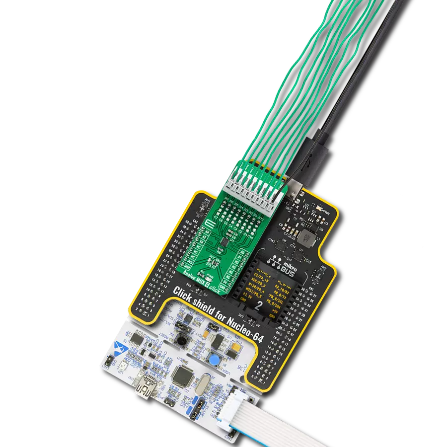
硬件概览
它是如何工作的?
Expand 17 Click基于Texas Instruments的TCAL6408,这是一个通过I2C协议提供输入/输出扩展的8位I/O扩展器。该Click板™是当处理开关、传感器、按钮、LED、风扇和其他外围设备时,添加更多I/O的理想解决方案。TCAL6408 IC具有灵活的I/O配置寄存器,提供可编程的输出驱动强度、锁存输入、可屏蔽中断、可编程的上拉/下拉电阻以及配置开漏或推挽输出的能力。这些高级功能确保了增强的I/O性能,提供了更高的速度、功耗优化以及降低的电磁干
扰(EMI)。TCAL6408支持独立的逻辑电源和主电源。逻辑电压通过3.3V的mikroBUS™电源轨供电,而主电源可以从mikroBUS™的3.3V供电或通过VIN端子提供的外部电源供电,范围为1.08V至3.6V。主电源选择通过VCCP SEL跳线进行管理,允许用户根据其应用的需求设置适当的电源。Expand 17 Click通过标准的2线I2C接口与主MCU通信,支持高达1MHz的时钟频率。I2C地址可以通过板上的ADDR SEL跳线轻松配置。此外,该板还使用了一个低电平有效的复位
(RST)引脚,用于初始化设备,以及一个开漏低电平有效中断(INT)引脚,用于通知输入状态的变化,确保高效处理外部事件和输入。该Click板™只能在3.3V逻辑电平下运行。在使用不同逻辑电平的MCU之前,必须进行适当的逻辑电平转换。此外,该Click板™还配备了包含易于使用的函数和示例代码的库,供进一步开发参考。

功能概述
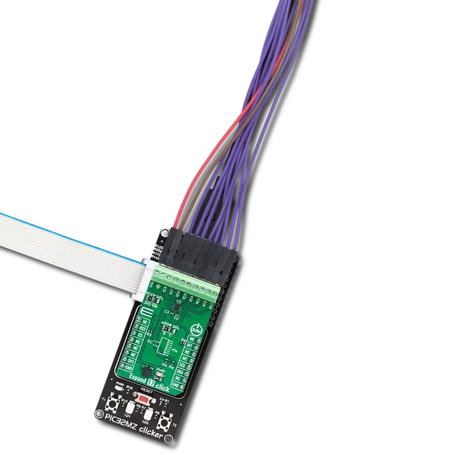
开发板
PIC32MZ Clicker 是一款紧凑型入门开发板,它将 Click 板™的灵活性带给您喜爱的微控制器,使其成为实现您想法的完美入门套件。它配备了一款板载 32 位带有浮点单元的 Microchip PIC32MZ 微控制器,一个 USB 连接器,LED 指示灯,按钮,一个 mikroProg 连接器,以及一个用于与外部电子设备接口的头部。得益于其紧凑的设计和清晰易识别的丝网标记,它提供了流畅且沉浸式的工作体验,允许在任
何情况下、任何地方都能访问。PIC32MZ Clicker 开 发套件的每个部分都包含了使同一板块运行最高效的必要组件。除了可以选择 PIC32MZ Clicker 的编程方式,使用 USB HID mikroBootloader 或通过外部 mikroProg 连接器为 PIC,dsPIC 或 PIC32 编程外,Clicker 板还包括一个干净且调节过的开发套件电源供应模块。USB Micro-B 连接可以提供多达 500mA 的电流,这足以操作所有板载和附加模块。所有
mikroBUS™ 本身支持的通信方法都在这块板上,包 括已经建立良好的 mikroBUS™ 插槽、重置按钮以及若干按钮和 LED 指示灯。PIC32MZ Clicker 是 Mikroe 生态系统的一个组成部分,允许您在几分钟内创建新的应用程序。它由 Mikroe 软件工具原生支持,得益于大量不同的 Click 板™(超过一千块板),其数量每天都在增长,它涵盖了原型制作的许多方面。

微控制器概述
MCU卡片 / MCU

建筑
PIC32
MCU 内存 (KB)
1024
硅供应商
Microchip
引脚数
64
RAM (字节)
524288
使用的MCU引脚
mikroBUS™映射器
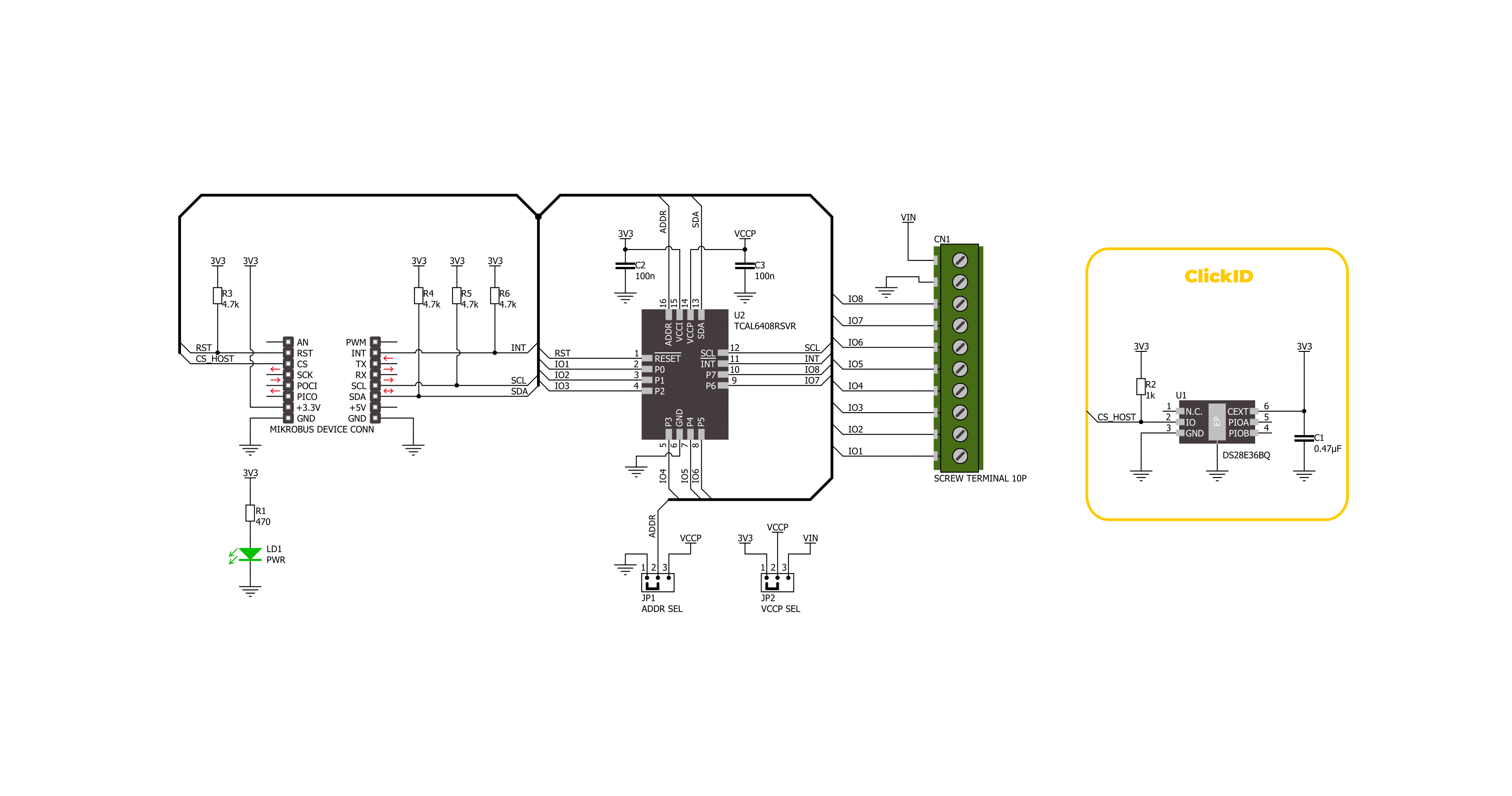
“仔细看看!”
Click board™ 原理图
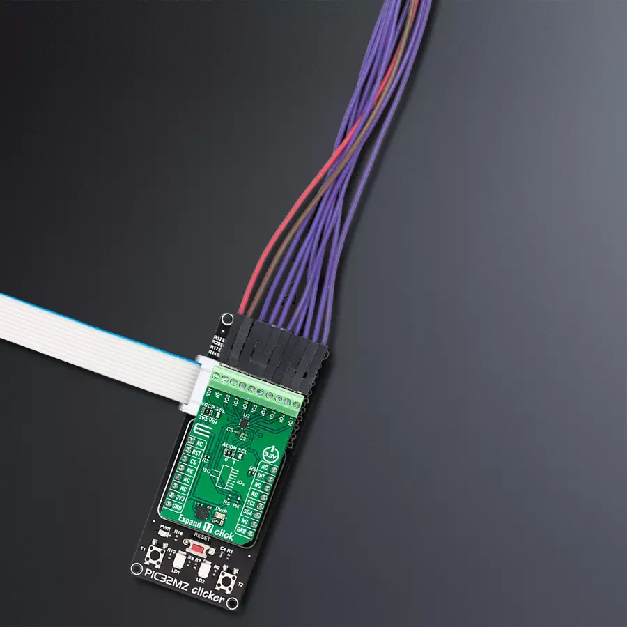
一步一步来
项目组装

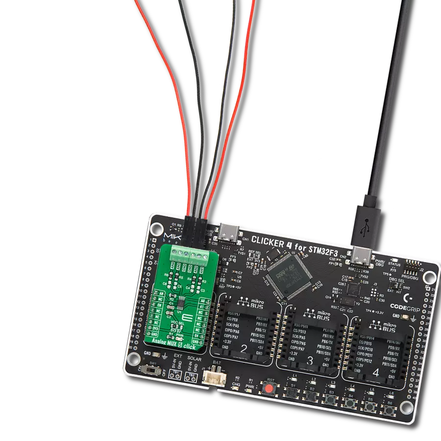
从选择您的开发板和Click板™开始。以PIC32MZ clicker作为您的开发板开始。


软件支持
库描述
该库包含 Expand 17 Click 驱动程序的 API。
关键功能:
expand17_set_io_dir- 此函数用于设置引脚的输入或输出方向。expand17_set_output_state- 此函数用于设置引脚的输出状态。expand17_get_input_state- 此函数用于获取引脚的输入状态。
开源
代码示例
完整的应用程序代码和一个现成的项目可以通过NECTO Studio包管理器直接安装到NECTO Studio。 应用程序代码也可以在MIKROE的GitHub账户中找到。
/*!
 * @file main.c
 * @brief Expand 17 Click example
 *
 * # Description
 * This example demonstrates the use of Expand 17 Click board by setting and reading
 * the ports state.
 *
 * The demo application is composed of two sections :
 *
 * ## Application Init
 * Initializes the driver and performs the Click default configuration which sets
 * half of pins as output ( IO5, IO6, IO7 and IO8 ) and the
 * half of the pins as inputs ( IO1, IO2, IO3 and IO4 ).
 *
 * ## Application Task
 * Sets the state of the output pins and then reads the status of the input pins
 * and displays the results on the USB UART approximately every 2 seconds.
 *
 * @note
 * In order for this example to work as intended it is necessary to connect the input and output pins
 * eg. IO1 and IO5, IO2 and IO6 etc. Floating input pins will be shown as a high state.
 *
 * @author Stefan Ilic
 *
 */

#include "board.h"
#include "log.h"
#include "expand17.h"

static expand17_t expand17;
static log_t logger;

void application_init ( void )
{
    log_cfg_t log_cfg;  /**< Logger config object. */
    expand17_cfg_t expand17_cfg;  /**< Click config object. */

    /**
     * Logger initialization.
     * Default baud rate: 115200
     * Default log level: LOG_LEVEL_DEBUG
     * @note If USB_UART_RX and USB_UART_TX
     * are defined as HAL_PIN_NC, you will
     * need to define them manually for log to work.
     * See @b LOG_MAP_USB_UART macro definition for detailed explanation.
     */
    LOG_MAP_USB_UART( log_cfg );
    log_init( &logger, &log_cfg );
    log_info( &logger, " Application Init " );

    // Click initialization.
    expand17_cfg_setup( &expand17_cfg );
    EXPAND17_MAP_MIKROBUS( expand17_cfg, MIKROBUS_1 );
    if ( I2C_MASTER_ERROR == expand17_init( &expand17, &expand17_cfg ) )
    {
        log_error( &logger, " Communication init." );
        for ( ; ; );
    }

    if ( EXPAND17_ERROR == expand17_default_cfg ( &expand17 ) )
    {
        log_error( &logger, " Default configuration." );
        for ( ; ; );
    }

    log_info( &logger, " Application Task " );
}

void application_task ( void )
{
    uint8_t input_state = 0;

    log_printf( &logger, " Setting output pins state: HIGH \r\n" );
    log_printf( &logger, " = = = = = = = = = = = = = = = = = \r\n" );
    expand17_set_output_state( &expand17, EXPAND17_NO_IO_PIN_MASK, EXPAND17_IO_5_PIN_MASK |
                                          EXPAND17_IO_6_PIN_MASK | EXPAND17_IO_7_PIN_MASK |
                                          EXPAND17_IO_8_PIN_MASK );

    log_printf( &logger, " State of input pins: \r\n" );
    log_printf( &logger, " = = = = = = = = = = = = = = = = = \r\n" );
    expand17_get_input_state( &expand17, &input_state );
    if ( input_state & EXPAND17_IO_1_PIN_MASK )
    {
        log_printf( &logger, " IO1 - HIGH \r\n" );
    }
    else
    {
        log_printf( &logger, " IO1 - LOW \r\n" );
    }
    if ( input_state & EXPAND17_IO_2_PIN_MASK )
    {
        log_printf( &logger, " IO2 - HIGH \r\n" );
    }
    else
    {
        log_printf( &logger, " IO2 - LOW \r\n" );
    }
    if ( input_state & EXPAND17_IO_3_PIN_MASK )
    {
        log_printf( &logger, " IO3 - HIGH \r\n" );
    }
    else
    {
        log_printf( &logger, " IO3 - LOW \r\n" );
    }
    if ( input_state & EXPAND17_IO_4_PIN_MASK )
    {
        log_printf( &logger, " IO4 - HIGH \r\n" );
    }
    else
    {
        log_printf( &logger, " IO4 - LOW \r\n" );
    }
    log_printf( &logger, " = = = = = = = = = = = = = = = = = \r\n" );
    Delay_ms ( 1000 );
    Delay_ms ( 1000 );

    log_printf( &logger, " Setting output pins state: LOW \r\n" );
    log_printf( &logger, " = = = = = = = = = = = = = = = = = \r\n" );
    expand17_set_output_state( &expand17, EXPAND17_IO_5_PIN_MASK | EXPAND17_IO_6_PIN_MASK |
                                          EXPAND17_IO_7_PIN_MASK | EXPAND17_IO_8_PIN_MASK,
                                          EXPAND17_NO_IO_PIN_MASK );

    log_printf( &logger, " State of input pins: \r\n" );
    log_printf( &logger, " = = = = = = = = = = = = = = = = = \r\n" );
    expand17_get_input_state( &expand17, &input_state );
    if ( input_state & EXPAND17_IO_1_PIN_MASK )
    {
        log_printf( &logger, " IO1 - HIGH \r\n" );
    }
    else
    {
        log_printf( &logger, " IO1 - LOW \r\n" );
    }
    if ( input_state & EXPAND17_IO_2_PIN_MASK )
    {
        log_printf( &logger, " IO2 - HIGH \r\n" );
    }
    else
    {
        log_printf( &logger, " IO2 - LOW \r\n" );
    }
    if ( input_state & EXPAND17_IO_3_PIN_MASK )
    {
        log_printf( &logger, " IO3 - HIGH \r\n" );
    }
    else
    {
        log_printf( &logger, " IO3 - LOW \r\n" );
    }
    if ( input_state & EXPAND17_IO_4_PIN_MASK )
    {
        log_printf( &logger, " IO4 - HIGH \r\n" );
    }
    else
    {
        log_printf( &logger, " IO4 - LOW \r\n" );
    }
    log_printf( &logger, " = = = = = = = = = = = = = = = = = \r\n" );
    Delay_ms ( 1000 );
    Delay_ms ( 1000 );
}

int main ( void )
{
    /* Do not remove this line or clock might not be set correctly. */
    #ifdef PREINIT_SUPPORTED
    preinit();
    #endif

    application_init( );

    for ( ; ; )
    {
        application_task( );
    }

    return 0;
}

// ------------------------------------------------------------------------ END