使用INA219和PIC32MZ2048EFM100为您的系统提供有价值的电力消耗信息
用于测量电力消耗的12位电源监控器
已发布 9月 18, 2024
点击板
Power Monitor 2 Click
开发板
Curiosity PIC32 MZ EF
编译器
NECTO Studio
微控制器单元
PIC32MZ2048EFM100
为嵌入式系统中的电源监控和管理提供有价值的信息
A
A
硬件概览
它是如何工作的?
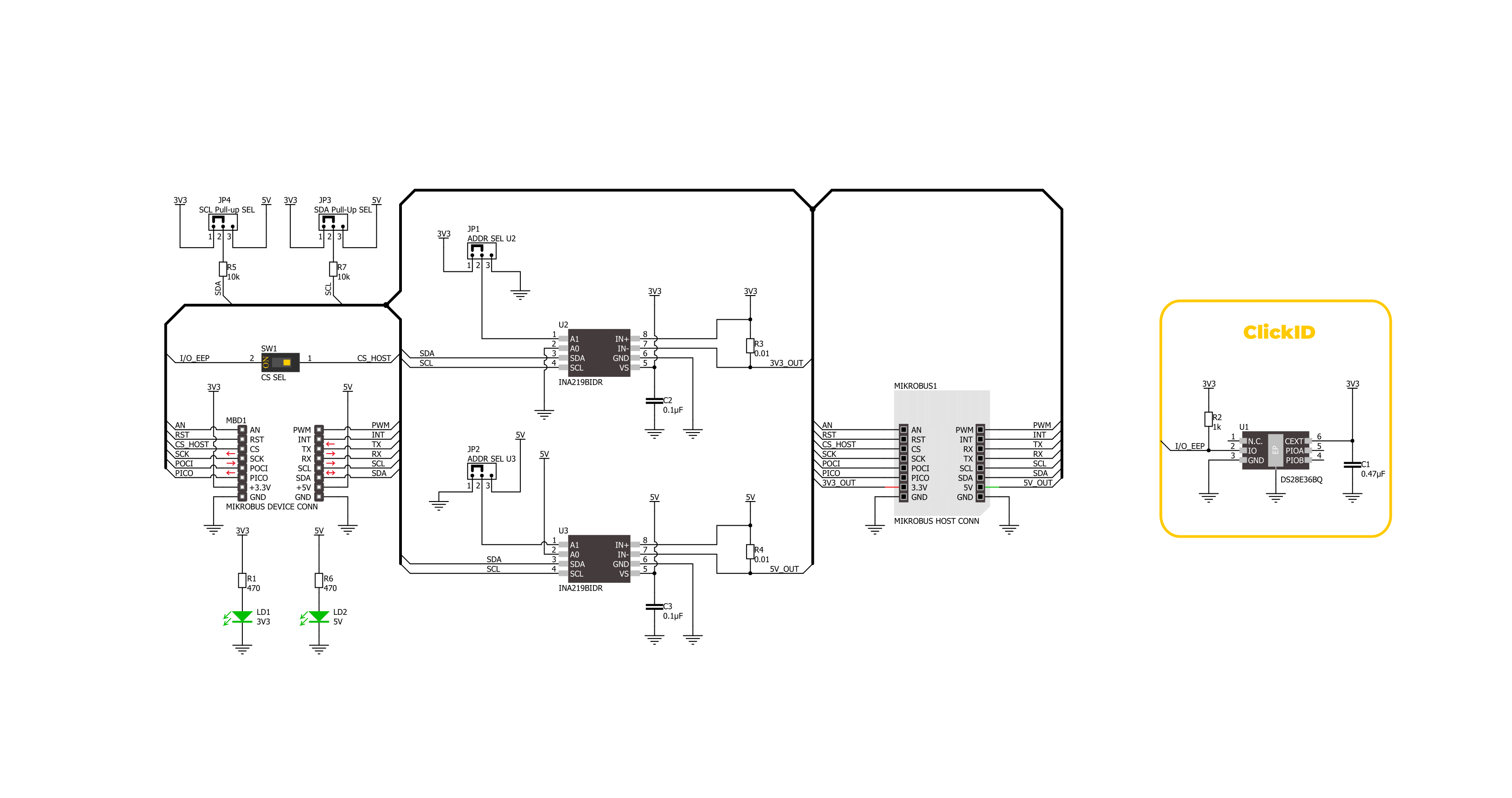
Power Monitoring 2 Click基于两个INA219,这是一款来自德州仪器的12位I2C输出数字电源监控器,专为精确的电源监控而设计。这些IC用于监控连接负载设备的电力消耗,测量附加mikroBUS™插座上两条独立电源轨——3.3V和5V的电流和电压。这种配置允许监控这两条电源线,非常适合评估插入板载mikroBUS™插座中的任何Click板™的功耗。得益于其灵活性,INA219允许在没有特殊电源排序的情况下进行电源监控,即使电源或总线电压独立存在或缺失时也可以监控电源。INA219提供电流、电压和功率的实时数字读数。它通过感应连接到相关总线的分流电阻(R3和R4)上的电压降来实现测量,能够处理0到
26V范围内的总线电压。该设备的可编程转换时间和滤波选项确保了在各种操作条件下的精确测量。此外,INA219提供可编程的校准值,当与内部乘法器结合时,能够直接读取电流(单位为安培)并通过乘法寄存器计算功率(单位为瓦特)。如前所述,INA219通过标准的2线I2C接口与主MCU通信,支持高达1MHz时钟频率的高速模式。Power Monitoring 2 Click上的每个INA219 IC都具有可配置的I2C地址,地址通过ADDR SEL跳线设置(U2或U3分别对应每个INA219)。通过将跳线定位到0或1,用户可以选择所需的I2C地址。此外,考虑到此Click板™可以在3.3V和5V逻辑电平下运行,I2C线路上的上拉电阻所连接
的电压也可以选择。通过调整I2C PULL-UP跳线选择适当的电压水平(3.3V或5V)。该板还具有一个板载开关CS SEL,它使mikroBUS™插座的CS线与板上的ClickID功能通信。通过将开关设置为ON位置,CS线被重定向,允许ClickID功能正常工作以识别连接的Click板™。此Click板™可以在3.3V或5V逻辑电压电平下运行。这样,支持3.3V和5V逻辑电平的MCU都可以正确使用通信线路。作为附加功能,它包括两个绿色LED指示灯,分别显示3.3V或5V电源轨是否处于活动状态。此外,该Click板™还配备了包含易于使用的函数和示例代码的库,可作为进一步开发的参考。

功能概述
开发板
Curiosity PIC32 MZ EF 开发板是一个完全集成的 32 位开发平台,特点是高性能的 PIC32MZ EF 系列(PIC32MZ2048EFM),该系列具有 2MB Flash、512KB RAM、集成的浮点单元(FPU)、加密加速器和出色的连接选项。它包括一个集成的程序员和调试器,无需额外硬件。用户可以通过 MIKROE
mikroBUS™ Click™ 适配器板扩展功能,通过 Microchip PHY 女儿板添加以太网连接功能,使用 Microchip 扩展板添加 WiFi 连接能力,并通过 Microchip 音频女儿板添加音频输入和输出功能。这些板完全集成到 PIC32 强大的软件框架 MPLAB Harmony 中,该框架提供了一个灵活且模块化的接口
来应用开发、一套丰富的互操作软件堆栈(TCP-IP、USB)和易于使用的功能。Curiosity PIC32 MZ EF 开发板提供了扩展能力,使其成为连接性、物联网和通用应用中快速原型设计的绝佳选择。

微控制器概述
MCU卡片 / MCU

建筑
PIC32
MCU 内存 (KB)
2048
硅供应商
Microchip
引脚数
100
RAM (字节)
524288
使用的MCU引脚
mikroBUS™映射器
“仔细看看!”
Click board™ 原理图
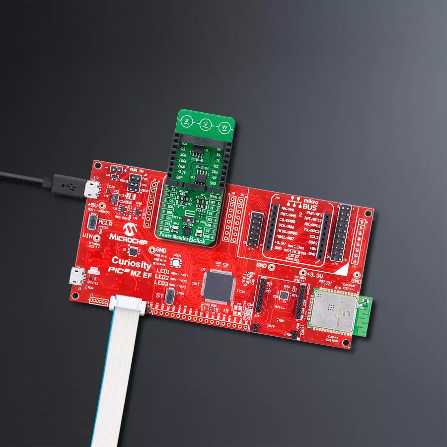
一步一步来
项目组装

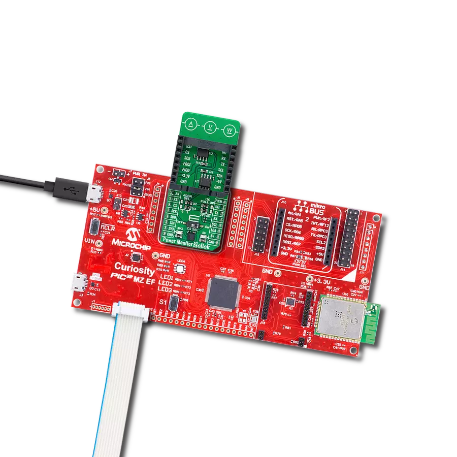
从选择您的开发板和Click板™开始。以Curiosity PIC32 MZ EF作为您的开发板开始。


软件支持
库描述
该库包含 Power Monitor 2 Click 驱动程序的 API。
关键功能:
powermonitor2_set_address- 此函数设置设备的从属地址。powermonitor2_read_data- 此函数读取分流电压、总线电压、电流和功率数据测量值。powermonitor2_read_data_avg- 此函数从num_conv样本中读取分流电压、总线电压、电流和功率数据的平均值。
开源
代码示例
完整的应用程序代码和一个现成的项目可以通过NECTO Studio包管理器直接安装到NECTO Studio。 应用程序代码也可以在MIKROE的GitHub账户中找到。
/*!
 * @file main.c
 * @brief Power Monitor 2 Click example
 *
 * # Description
 * This example demonstrates the use of Power Monitor 2 Click by reading and displaying
 * the power consumption at 3V3 and 5V of the connected Click board.
 *
 * The demo application is composed of two sections :
 *
 * ## Application Init
 * Initializes the driver and performs the Click default configuration.
 *
 * ## Application Task
 * Reads the voltage, current, and power measurements from U2 and U3 sensors averaged
 * from 20 samples and displays the results on the USB UART.
 *
 * @author Stefan Filipovic
 *
 */

#include "board.h"
#include "log.h"
#include "powermonitor2.h"

static powermonitor2_t powermonitor2;
static log_t logger;

void application_init ( void )
{
    log_cfg_t log_cfg;  /**< Logger config object. */
    powermonitor2_cfg_t powermonitor2_cfg;  /**< Click config object. */

    /**
     * Logger initialization.
     * Default baud rate: 115200
     * Default log level: LOG_LEVEL_DEBUG
     * @note If USB_UART_RX and USB_UART_TX
     * are defined as HAL_PIN_NC, you will
     * need to define them manually for log to work.
     * See @b LOG_MAP_USB_UART macro definition for detailed explanation.
     */
    LOG_MAP_USB_UART( log_cfg );
    log_init( &logger, &log_cfg );
    log_info( &logger, " Application Init " );

    // Click initialization.
    powermonitor2_cfg_setup( &powermonitor2_cfg );
    POWERMONITOR2_MAP_MIKROBUS( powermonitor2_cfg, MIKROBUS_1 );
    if ( I2C_MASTER_ERROR == powermonitor2_init( &powermonitor2, &powermonitor2_cfg ) )
    {
        log_error( &logger, " Communication init." );
        for ( ; ; );
    }

    if ( POWERMONITOR2_ERROR == powermonitor2_default_cfg ( &powermonitor2 ) )
    {
        log_error( &logger, " Default configuration." );
        for ( ; ; );
    }

    log_info( &logger, " Application Task " );
}

void application_task ( void )
{
    powermonitor2_data_t pm_3v3, pm_5v;

    powermonitor2_set_address ( &powermonitor2, powermonitor2.address_3v3 );
    if ( POWERMONITOR2_OK == powermonitor2_read_data_avg ( &powermonitor2, POWERMONITOR2_DEFAULT_NUM_CONV, &pm_3v3 ) )
    {
        log_printf( &logger, " --- 3V3 Power Monitor ---\r\n" );
        log_printf( &logger, " Voltage: %.3f V\r\n", pm_3v3.bus_v );
        log_printf( &logger, " Current: %.3f A\r\n", pm_3v3.current );
        log_printf( &logger, " Power: %.2f W\r\n", pm_3v3.power );
        log_printf( &logger, " -------------------------\r\n" );
    }

    powermonitor2_set_address ( &powermonitor2, powermonitor2.address_5v );
    if ( POWERMONITOR2_OK == powermonitor2_read_data_avg ( &powermonitor2, POWERMONITOR2_DEFAULT_NUM_CONV, &pm_5v ) )
    {
        log_printf( &logger, " ---- 5V Power Monitor ---\r\n" );
        log_printf( &logger, " Voltage: %.3f V\r\n", pm_5v.bus_v );
        log_printf( &logger, " Current: %.3f A\r\n", pm_5v.current );
        log_printf( &logger, " Power: %.2f W\r\n", pm_5v.power );
        log_printf( &logger, " -------------------------\r\n" );
    }

    Delay_ms ( 1000 );
}

int main ( void )
{
    /* Do not remove this line or clock might not be set correctly. */
    #ifdef PREINIT_SUPPORTED
    preinit();
    #endif

    application_init( );

    for ( ; ; )
    {
        application_task( );
    }

    return 0;
}

// ------------------------------------------------------------------------ END
额外支持
资源
类别:电流传感器