使用BM14270和ATmega328在不接触导体的情况下测量电流流动
基于磁阻(MI)传感器的电流感应解决方案
已发布 11月 19, 2024
点击板
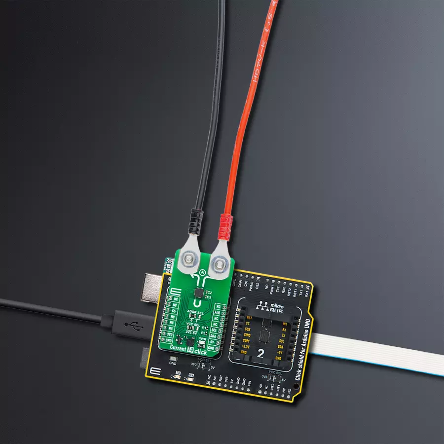
Current 14 Click
开发板
Arduino UNO Rev3
编译器
NECTO Studio
微控制器单元
ATmega328
监测工业机器和设备的电流消耗
A
A
硬件概览
它是如何工作的?
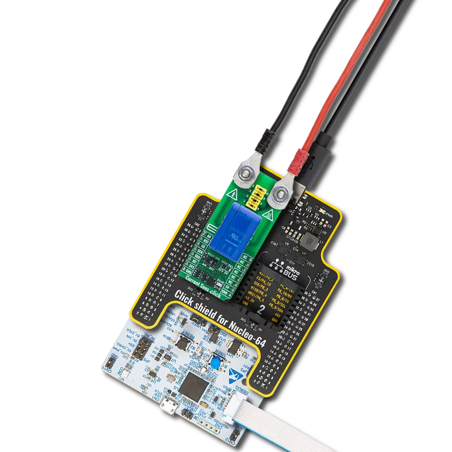
Current 14 Click 基于来自 ROHM 半导体的 BM14270 (BM14270AMUV-LB) 磁性电流传感器 IC。专为工业市场的长期支持而设计,这种无核、非接触式电流感应解决方案使用磁性 MI(磁阻抗)传感器,能够在最小的功率损耗下实现精确的电流测量。其非侵入式设计使其能够测量导体中流动的电流而无需直接接触,从而高效且适用于各种应用场景。该 Click board™ 是需要精确电流监测而不向电路引入额外负载或损耗的理想解决方案,能够在要求苛刻的环境中提供强大的支持。Current 14 Click 使用标准的 2
线 I2C 通信协议,使主控 MCU 能够控制 TSC1641。I2C 接口支持高达 400kHz 的时钟频率,并可以通过 ADDR SEL 跳线选择 I2C 地址。数据输出通过 I2C 接口以 14 位数字格式提供,在电流检测中提供高精度。传感器的磁测量范围可达 ±280μT(典型值),具有 0.045μT/LSB 的磁灵敏度,能够在各种应用中实现精细可靠的测量。这种能力尤其适用于工业设备监控、电力测量仪表、不间断电源 (UPS) 和电力调节系统。此 Click board™ 还包括一个警报中断引脚 ALR,作为数据准备指示器。除了标准的接口引脚
外,ALR 引脚在有新测量数据时发出信号,简化了数据采集过程,并确保主控 MCU 实时更新。这一功能增强了该板在实时监控应用中的响应性,特别适合动态系统中需要精确和即时电流数据的场景。此 Click board™ 可在 3.3V 或 5V 逻辑电压电平下运行,可通过 VCC SEL 跳线选择电压。这种设计确保 3.3V 和 5V 的 MCU 均可正常使用通信线路。此外,该 Click board™ 配有易于使用的函数库和示例代码,供进一步开发参考。

功能概述
开发板
Arduino UNO 是围绕 ATmega328P 芯片构建的多功能微控制器板。它为各种项目提供了广泛的连接选项,具有 14 个数字输入/输出引脚,其中六个支持 PWM 输出,以及六个模拟输入。其核心组件包括一个 16MHz 的陶瓷谐振器、一个 USB 连接器、一个电
源插孔、一个 ICSP 头和一个复位按钮,提供了为板 子供电和编程所需的一切。UNO 可以通过 USB 连接到计算机,也可以通过 AC-to-DC 适配器或电池供电。作为第一个 USB Arduino 板,它成为 Arduino 平台的基准,"Uno" 符号化其作为系列首款产品的地
位。这个名称选择,意为意大利语中的 "一",是为了 纪念 Arduino Software(IDE)1.0 的推出。最初与 Arduino Software(IDE)版本1.0 同时推出,Uno 自此成为后续 Arduino 发布的基础模型,体现了该平台的演进。

微控制器概述
MCU卡片 / MCU

建筑
AVR
MCU 内存 (KB)
32
硅供应商
Microchip
引脚数
32
RAM (字节)
2048
你完善了我!
配件
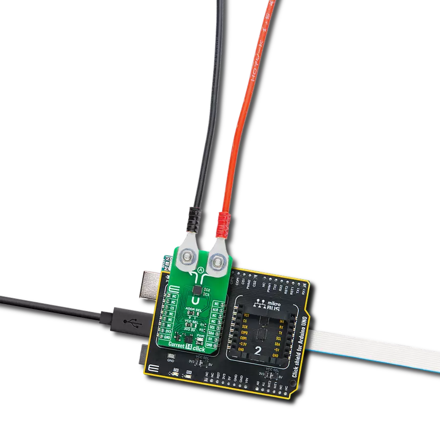
Click Shield for Arduino UNO 具有两个专有的 mikroBUS™ 插座,使所有 Click board™ 设备能够轻松与 Arduino UNO 板进行接口连接。Arduino UNO 是一款基于 ATmega328P 的微控制器开发板,为用户提供了一种经济实惠且灵活的方式来测试新概念并构建基于 ATmega328P 微控制器的原型系统,结合了性能、功耗和功能的多种配置选择。Arduino UNO 具有 14 个数字输入/输出引脚(其中 6 个可用作 PWM 输出)、6 个模拟输入、16 MHz 陶瓷谐振器(CSTCE16M0V53-R0)、USB 接口、电源插座、ICSP 头和复位按钮。大多数 ATmega328P 微控制器的引脚都连接到开发板左右两侧的 IO 引脚,然后再连接到两个 mikroBUS™ 插座。这款 Click Shield 还配备了多个开关,可执行各种功能,例如选择 mikroBUS™ 插座上模拟信号的逻辑电平,以及选择 mikroBUS™ 插座本身的逻辑电压电平。此外,用户还可以通过现有的双向电平转换电压转换器使用任何 Click board™,无论 Click board™ 运行在 3.3V 还是 5V 逻辑电压电平。一旦将 Arduino UNO 板与 Click Shield for Arduino UNO 连接,用户即可访问数百种 Click board™,并兼容 3.3V 或 5V 逻辑电压电平的设备。

使用的MCU引脚
mikroBUS™映射器
“仔细看看!”
Click board™ 原理图

一步一步来
项目组装

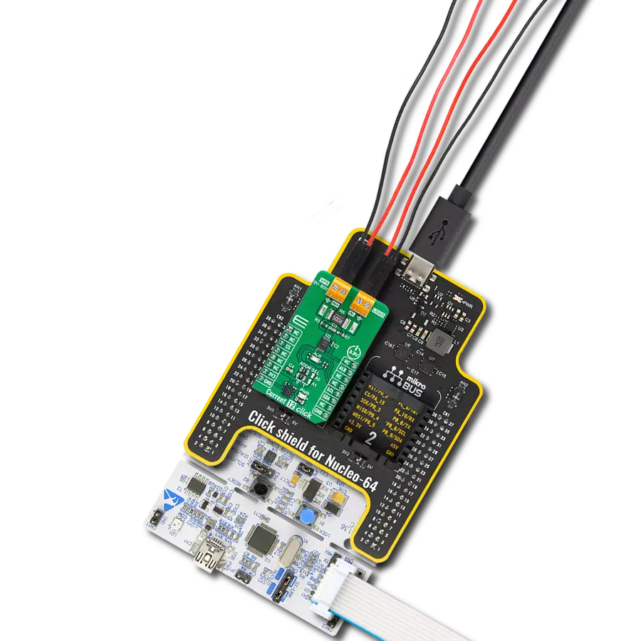
从选择您的开发板和Click板™开始。以Arduino UNO Rev3作为您的开发板开始。


软件支持
库描述
This library contains API for Curr Click driver.
Key functions:
example1- Exampleexample2- Exampleexample3- Example
开源
代码示例
完整的应用程序代码和一个现成的项目可以通过NECTO Studio包管理器直接安装到NECTO Studio。 应用程序代码也可以在MIKROE的GitHub账户中找到。
/*!
* @file main.c
* @brief Current 14 Click example
*
* # Description
* This example demonstrates the use of Current 11 Click board by reading and
* displaying the input current measurements.
*
* The demo application is composed of two sections :
*
* ## Application Init
* Initializes the driver and calibrates the zero current offset and data resolution
* at 3A load current.
*
* ## Application Task
* Reads the input current measurements and displays the results on the USB UART
* approximately once per second.
*
* @author Stefan Filipovic
*
*/
#include "board.h"
#include "log.h"
#include "current14.h"
static current14_t current14;
static log_t logger;
void application_init ( void )
{
log_cfg_t log_cfg; /**< Logger config object. */
current14_cfg_t current14_cfg; /**< Click config object. */
/**
* Logger initialization.
* Default baud rate: 115200
* Default log level: LOG_LEVEL_DEBUG
* @note If USB_UART_RX and USB_UART_TX
* are defined as HAL_PIN_NC, you will
* need to define them manually for log to work.
* See @b LOG_MAP_USB_UART macro definition for detailed explanation.
*/
LOG_MAP_USB_UART( log_cfg );
log_init( &logger, &log_cfg );
log_info( &logger, " Application Init " );
// Click initialization.
current14_cfg_setup( ¤t14_cfg );
CURRENT14_MAP_MIKROBUS( current14_cfg, MIKROBUS_1 );
if ( I2C_MASTER_ERROR == current14_init( ¤t14, ¤t14_cfg ) )
{
log_error( &logger, " Communication init." );
for ( ; ; );
}
if ( CURRENT14_ERROR == current14_default_cfg ( ¤t14 ) )
{
log_error( &logger, " Default configuration." );
for ( ; ; );
}
log_printf( &logger, " Calibrating zero current offset in 5 seconds...\r\n" );
log_printf( &logger, " Make sure no current flows through the sensor during the calibration process.\r\n" );
for ( uint8_t cnt = 5; cnt > 0; cnt-- )
{
log_printf( &logger, " %u\r\n", ( uint16_t ) cnt );
Delay_ms ( 1000 );
}
if ( CURRENT14_ERROR == current14_calib_offset ( ¤t14 ) )
{
log_error( &logger, " Calibrate offset." );
for ( ; ; );
}
log_printf( &logger, " Offset calibration DONE.\r\n\n" );
log_printf( &logger, " Calibrating data resolution in 5 seconds...\r\n" );
log_printf( &logger, " Keep the load current set at 3A during the calibration process.\r\n" );
for ( uint8_t cnt = 5; cnt > 0; cnt-- )
{
log_printf( &logger, " %u\r\n", ( uint16_t ) cnt );
Delay_ms ( 1000 );
}
if ( CURRENT14_ERROR == current14_calib_resolution ( ¤t14, 3.0f ) )
{
log_error( &logger, " Calibrate resolution." );
for ( ; ; );
}
log_printf( &logger, " Data resolution calibration DONE.\r\n" );
log_info( &logger, " Application Task " );
}
void application_task ( void )
{
float current = 0;
if ( CURRENT14_OK == current14_get_current ( ¤t14, ¤t ) )
{
log_printf ( &logger, " Current: %.3f A\r\n\n", current );
}
}
int main ( void )
{
/* Do not remove this line or clock might not be set correctly. */
#ifdef PREINIT_SUPPORTED
preinit();
#endif
application_init( );
for ( ; ; )
{
application_task( );
}
return 0;
}
// ------------------------------------------------------------------------ END
额外支持
资源
类别:电流传感器