实现无缝集成,释放无限创造力,使用我们的Shuttle板和PIC18F2525
扩展。增强。超越。

已发布 6月 25, 2024
点击板
Shuttle Click
开发板
EasyPIC v8
编译器
NECTO Studio
微控制器单元
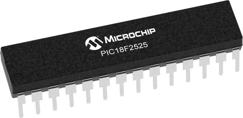
PIC18F2525
无缝扩展您的开发平台功能,释放无限可能。
A
A
硬件概览
它是如何工作的?
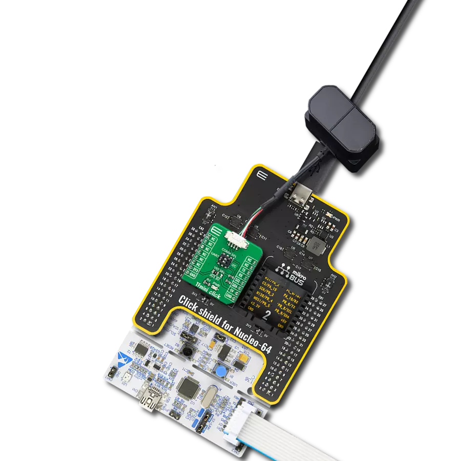
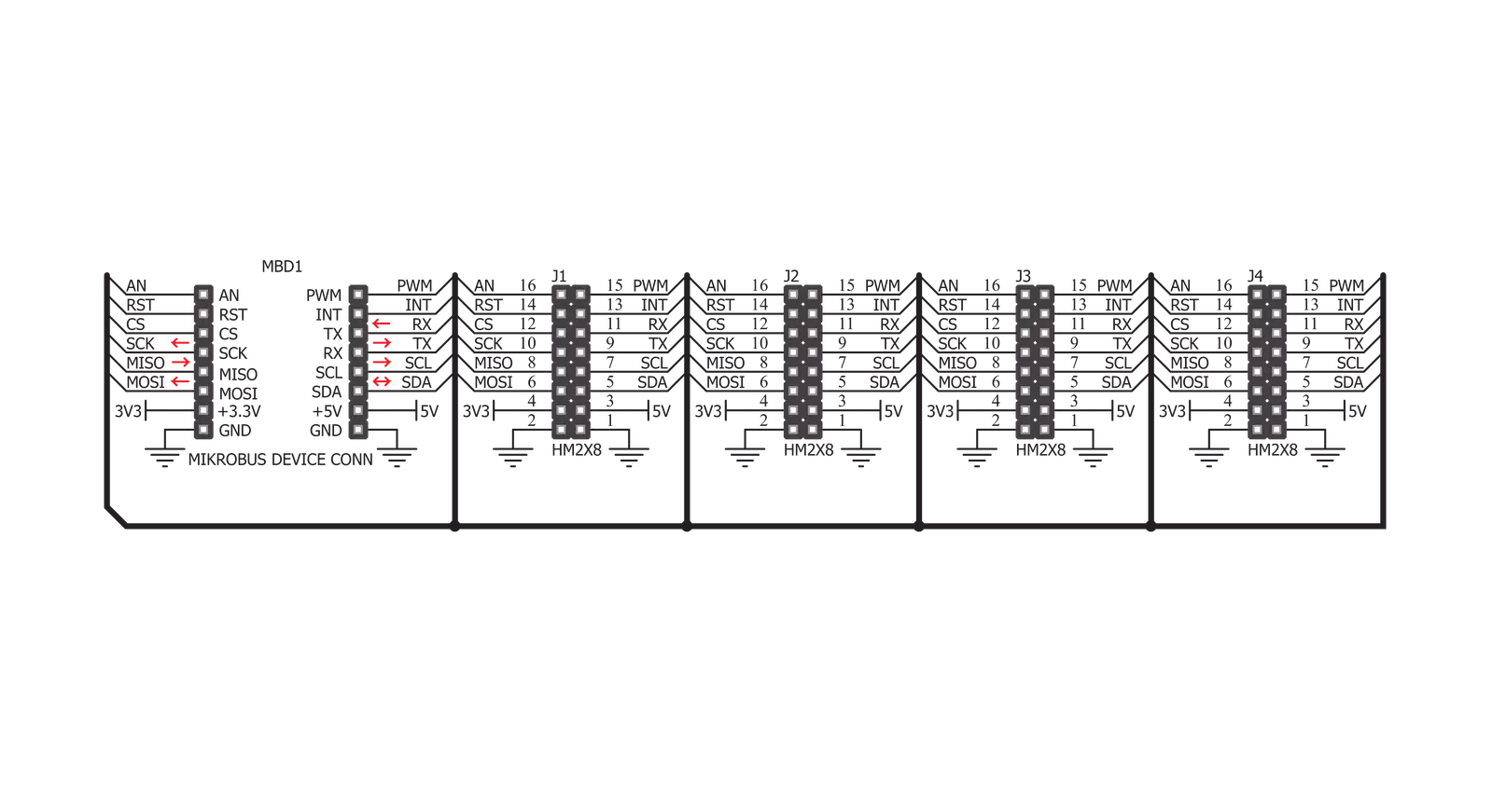
Shuttle Click由高质量的PCB组成,可以像其他点击板一样连接到mikroBUS™。Shuttle click的中心部分装有四个ICD BOX头。这四个头中的每一个都通过扁平排线连接到附加板上的同一类型的头,也称为mikroBUS Shuttle。由于ICD BOX头,连接保持牢固稳定。除了ICD BOX头之外,这些mikroBUS Shuttle附加板还配备了一个mikroBUS™,以便可以将点击板安全地安装在上面。这种堆叠拓扑结构允许轻松操作和重新配置堆叠的点击板™,始终保持完美的连接质量。当需要通过更多的mikroBUS™插槽扩展开发系统时,可以在
其中一个空闲的mikroBUS Shuttle上安装另一个Shuttle Click,从而实现更多的连接。这使得堆叠容量几乎是无限的。然而,应注意不要使mikroBUS™线太长。在这种情况下,通信频率可能需要降低一点来补偿较长的mikroBUS™信号线。连接到Shuttle click的mikroBUS™线路通过所有四个ICD BOX头共享-每个四个ICD BOX 2x8引脚头都镜像了连接的mikroBUS™的引脚。因此,每个mikroBUS Shuttle附加板都与连接到相同Shuttle click的其他mikroBUS Shuttles共享相同的mikroBUS™引脚。因此,在处理共享mikroBUS™上相同引脚的点击板™时,
应特别小心,无论是用于通信(SPI、UART、I2C)还是其他目的(RST、INT或其他用作GPIO的引脚)。例如,I2C和1-Wire协议是考虑到堆叠而设计的,因此这些协议已经具备了避免冲突的机制。只需更改点击板™的从机地址,即使在共享相同的通信引脚的情况下,数据冲突也不会成为问题。此外,由于所有堆叠的点击板™共享相同的电源轨,因此在组合具有大功耗的点击板™时应格外小心。所有点击板™的功耗总和不应超过开发系统可以提供的最大功率。

功能概述
开发板
EasyPIC v8 是一款专为快速开发嵌入式应用的需求而特别设计的开发板。它支持许多高引脚计数的8位PIC微控制器,来自Microchip,无论它们的引脚数量如何,并且具有一系列独特功能,例如首次集成的调试器/程序员。开发板布局合理,设计周到,使得最终用户可以在一个地方找到所有必要的元素,如开关、按钮、指示灯、连接器等。得益于创新的制造技术,EasyPIC v8 提供了流畅而沉浸式的工作体验,允许在任何情况下、任何地方、任何时候都能访问。
EasyPIC v8 开发板的每个部分都包含了使同一板块运行最高效的必要组件。除了先进的集成CODEGRIP程 序/调试模块,该模块提供许多有价值的编程/调试选项和与Mikroe软件环境的无缝集成外,该板还包括一个干净且调节过的开发板电源供应模块。它可以使用广泛的外部电源,包括电池、外部12V电源供应和通过USB Type-C(USB-C)连接器的电源。通信选项如USB-UART、USB DEVICE和CAN也包括在内,包括 广受好评的mikroBUS™标准、两种显示选项(图形和
基于字符的LCD)和几种不同的DIP插座。这些插座覆盖了从最小的只有八个至四十个引脚的8位PIC MCU的广泛范围。EasyPIC v8 是Mikroe快速开发生态系统的一个组成部分。它由Mikroe软件工具原生支持,得益于大量不同的Click板™(超过一千块板),其数量每天都在增长,它涵盖了原型制作和开发的许多方面。

微控制器概述
MCU卡片 / MCU
建筑
PIC
MCU 内存 (KB)
48
硅供应商
Microchip
引脚数
28
RAM (字节)
3968
使用的MCU引脚
mikroBUS™映射器
“仔细看看!”
Click board™ 原理图
一步一步来
项目组装

从选择您的开发板和Click板™开始。以EasyPIC v8作为您的开发板开始。


实时跟踪您的结果
应用程序输出
1. 应用程序输出 - 在调试模式下,“应用程序输出”窗口支持实时数据监控,直接提供执行结果的可视化。请按照提供的教程正确配置环境,以确保数据正确显示。

2. UART 终端 - 使用UART Terminal通过USB to UART converter监视数据传输,实现Click board™与开发系统之间的直接通信。请根据项目需求配置波特率和其他串行设置,以确保正常运行。有关分步设置说明,请参考提供的教程。

3. Plot 输出 - Plot功能提供了一种强大的方式来可视化实时传感器数据,使趋势分析、调试和多个数据点的对比变得更加直观。要正确设置,请按照提供的教程,其中包含使用Plot功能显示Click board™读数的分步示例。在代码中使用Plot功能时,请使用以下函数:plot(insert_graph_name, variable_name);。这是一个通用格式,用户需要将“insert_graph_name”替换为实际图表名称,并将“variable_name”替换为要显示的参数。

软件支持
库描述
这个库包含了Shuttle Click驱动程序的API。
关键功能:
shuttle_set_pin_high- 此函数将指定引脚的输出电压设置为高电平。shuttle_set_pin_low- 此函数将指定引脚的输出电压设置为低电平。
开源
代码示例
完整的应用程序代码和一个现成的项目可以通过NECTO Studio包管理器直接安装到NECTO Studio。 应用程序代码也可以在MIKROE的GitHub账户中找到。
/*!
 * \file
 * \brief Shuttle Click example
 *
 * # Description
 * This example showcases how to initialize, configure and use the Terminal Click. It is a simple
 * GPIO Click which uses high-quality PCB design, four ICD BOX headers and flat ribbon cables to
 * enable stable communication and easy stacking of other Click modules.
 *
 * The demo application is composed of two sections :
 *
 * ## Application Init
 * This function initializes and configures the Click and logger modules.
 *
 * ## Application Task
 * This function sets the output on all the pins (one by one) on the left side to high, going
 * from top to bottom and then does the same with the ones on the right side, after which it
 * sets all pins to high and after one second sets them back to low.
 *
 * \author MikroE Team
 *
 */
// ------------------------------------------------------------------- INCLUDES

#include "board.h"
#include "log.h"
#include "shuttle.h"

// ------------------------------------------------------------------ VARIABLES

static shuttle_t shuttle;
static log_t logger;

static digital_out_t *pin_addr[ 12 ] =
{
    &shuttle.mosi,    // 0 MOSI
    &shuttle.miso,    // 1 MISO
    &shuttle.sck,     // 2 SCK
    &shuttle.cs,      // 3 CS
    &shuttle.rst,     // 4 RST
    &shuttle.an,      // 5 AN
    &shuttle.pwm,     // 6 PWM
    &shuttle.int_pin, // 7 INT
    &shuttle.tx_pin,  // 8 TX
    &shuttle.rx_pin,  // 9 RX
    &shuttle.scl,     // 10 SCL
    &shuttle.sda      // 11 SDA
};

// ------------------------------------------------------- ADDITIONAL FUNCTIONS

static void blink ( digital_out_t *pin )
{
    shuttle_set_pin_high( pin );
    Delay_100ms( );
    shuttle_set_pin_low( pin );
}

static void all_on ( )
{
   int i;

   for( i = 0; i < 12; i++ )
   {
        shuttle_set_pin_high( pin_addr[ i ] );
   }
}

static void all_off ( )
{
   int i;

   for( i = 0; i < 12; i++ )
   {
        shuttle_set_pin_low( pin_addr[ i ] );
   }
}

// ------------------------------------------------------ APPLICATION FUNCTIONS

void application_init ( )
{
    log_cfg_t log_cfg;
    shuttle_cfg_t cfg;

    /**
     * Logger initialization.
     * Default baud rate: 115200
     * Default log level: LOG_LEVEL_DEBUG
     * @note If USB_UART_RX and USB_UART_TX
     * are defined as HAL_PIN_NC, you will
     * need to define them manually for log to work.
     * See @b LOG_MAP_USB_UART macro definition for detailed explanation.
     */
    LOG_MAP_USB_UART( log_cfg );
    log_init( &logger, &log_cfg );
    log_info(&logger, "---- Application Init ----");

    //  Click initialization.

    shuttle_cfg_setup( &cfg );
    SHUTTLE_MAP_MIKROBUS( cfg, MIKROBUS_1 );
    shuttle_init( &shuttle, &cfg );
}

void application_task ( )
{
    int i;

    for( i = 0; i < 12; i++ )
    {
        blink( pin_addr[ i ] );
    }

    all_on( );
    Delay_1sec( );
    all_off( );
}

int main ( void )
{
    /* Do not remove this line or clock might not be set correctly. */
    #ifdef PREINIT_SUPPORTED
    preinit();
    #endif

    application_init( );

    for ( ; ; )
    {
        application_task( );
    }

    return 0;
}

// ------------------------------------------------------------------------ END