优化引脚利用率,减少板载复杂性,使用 CY8C9540A 和 PIC18F57Q43
升级您的 I/O 游戏!
已发布 6月 26, 2024
点击板
EXPAND 7 Click
开发板
Curiosity Nano with PIC18F57Q43
编译器
NECTO Studio
微控制器单元
PIC18F57Q43
体验我们I/O引脚扩展解决方案的多功能性,为您提供所需的灵活性和控制力,以优化您的项目,减少复杂性,并增强连接性。
A
A
硬件概览
它是如何工作的?
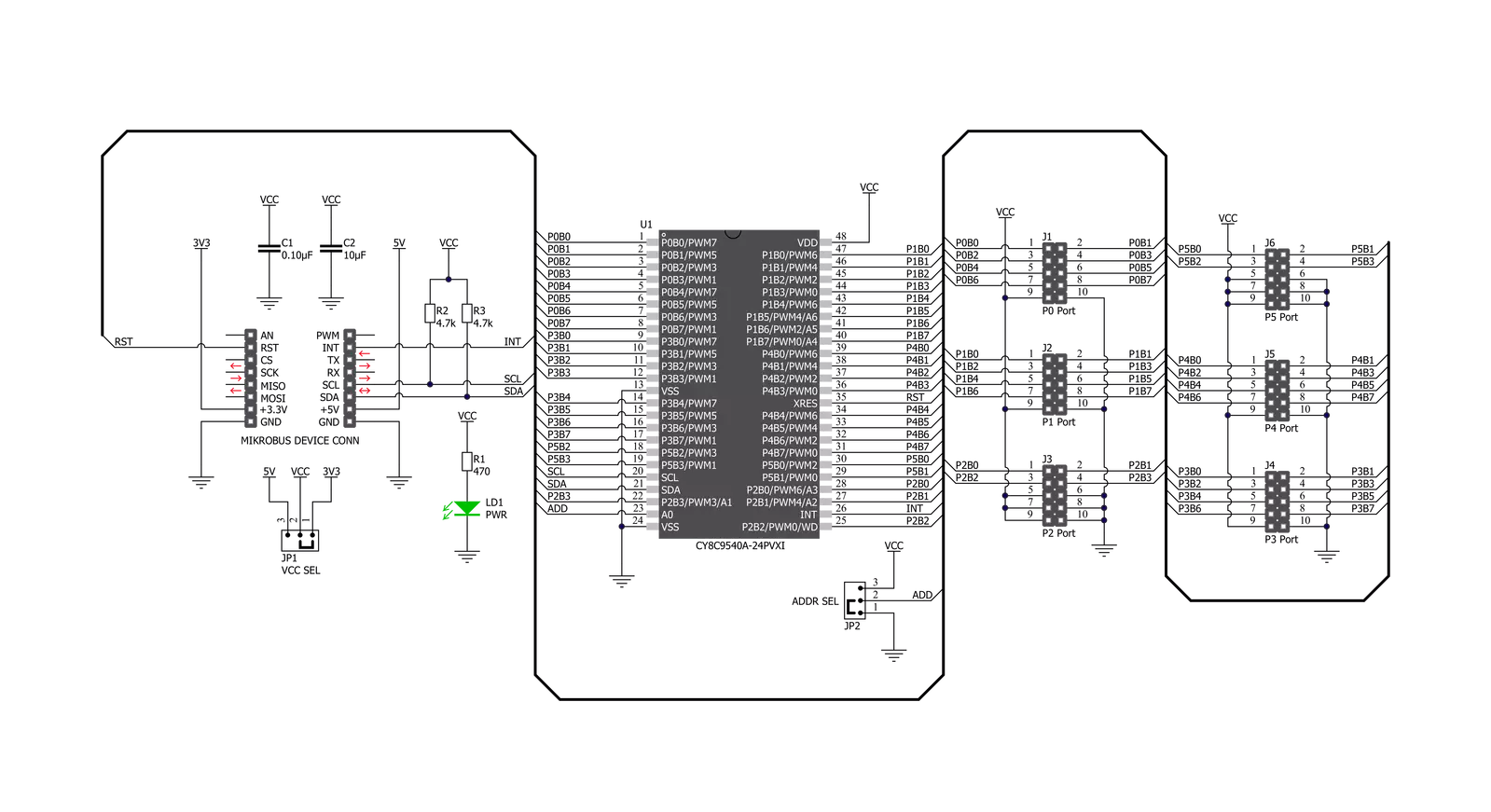
EXPAND 7 Click基于Infineon的CY8C9540A,这是一款具有EEPROM和八个独立可配置8位PWM输出的40位I/O扩展器。CY8C9540A的主要模块包括控制单元、PWM、EEPROM和I/O端口。I/O扩展器的数据引脚可以独立分配为输入、输出或PWM输出,并且可以配置为开漏或集电极、强驱动(10 mA源,25 mA沉)、上拉或下拉电阻,或高阻抗,这些可以在端口驱动模式寄存器中选择。它作为两个I2C外围设备运行,第一个设备是多端口I/O扩展器(单个I2C地址通过寄存器访问所有端口),第二个是具有11 Kbyte地址空间的串行EEPROM。配置和输出寄存器设置可以
作为用户默认值存储在EEPROM的专用部分中。如果用户默认值存储在EEPROM中,它们将在上电序列中恢复到端口。EEPROM是字节可读的,并支持逐字节写入。此Click板™上的端口2的引脚3可以配置为EEPROM写入禁用(WD)输入,当设置为高时阻止写操作。配置寄存器也可以关闭EEPROM操作。EXPAND 7 Click通过标准I2C 2线接口与MCU通信,最大频率为100kHz。默认情况下,CY8C9540A有两种可能的I2C从设备地址格式:第一种用于访问多端口设备,第二种用于访问EEPROM。I2C从设备地址的选择是通过设置CY8C9540A的A0引脚上的逻辑电平来执行的,可以使用标
记为ADDR SEL的SMD跳线完成。它还生成一个可编程中断信号,路由到mikroBUS™的INT引脚,这可以通知系统主设备其端口上有传入数据或PWM输出状态已更改。路由到mikroBUS™插座RST引脚的复位信号类似于POR(上电复位)功能。当CY8C9540A处于复位状态时,所有输入和输出引脚都保持在默认的高阻状态。此Click板™可以通过VCC SEL跳线选择3.3V或5V逻辑电压水平运行。这样,3.3V和5V的MCU都可以正确使用通信线。此外,此Click板™配备了一个包含易于使用的函数和示例代码的库,可用作进一步开发的参考。


功能概述
开发板
PIC18F57Q43 Curiosity Nano 评估套件是一款尖端的硬件平台,旨在评估 PIC18-Q43 系列内的微控制器。其设计的核心是包含了功能强大的 PIC18F57Q43 微控制器(MCU),提供先进的功能和稳健的性能。这个评估套件的关键特点包括一个黄 色用户 LED 和一个响应灵敏的机械用户开关,提供无
缝的交互和测试。为一个 32.768kHz 水晶振荡器足迹提供支持,确保精准的定时能力。套件内置的调试器拥有一个绿色电源和状态 LED,使编程和调试变得直观高效。此外,增强其实用性的还有虚拟串行端口 (CDC)和一个调试 GPIO 通道(DGI GPIO),提供广泛的连接选项。该套件通过 USB 供电,拥有由
MIC5353 LDO 调节器提供支持的可调目标电压功能,确保在 1.8V 至 5.1V 的输出电压范围内稳定运行,最大输出电流为 500mA,受环境温度和电压限制。

微控制器概述
MCU卡片 / MCU

建筑
PIC
MCU 内存 (KB)
128
硅供应商
Microchip
引脚数
48
RAM (字节)
8196
你完善了我!
配件
Curiosity Nano Base for Click boards 是一款多功能硬件扩展平台,专为简化 Curiosity Nano 套件与扩展板之间的集成而设计,特别针对符合 mikroBUS™ 标准的 Click 板和 Xplained Pro 扩展板。这款创新的基板(屏蔽板)提供了无缝的连接和扩展可能性,简化了实验和开发过程。主要特点包括从 Curiosity Nano 套件提供 USB 电源兼容性,以及为增强灵活性而提供的另一种外部电源输入选项。板载锂离子/锂聚合物充电器和管理电路确保电池供电应用的平稳运行,简化了使用和管理。此外,基板内置了一个固定的 3.3V 电源供应单元,专用于目标和 mikroBUS™ 电源轨,以及一个固定的 5.0V 升压转换器,专供 mikroBUS™ 插座的 5V 电源轨,为各种连接设备提供稳定的电力供应。

使用的MCU引脚
mikroBUS™映射器
“仔细看看!”
Click board™ 原理图
一步一步来
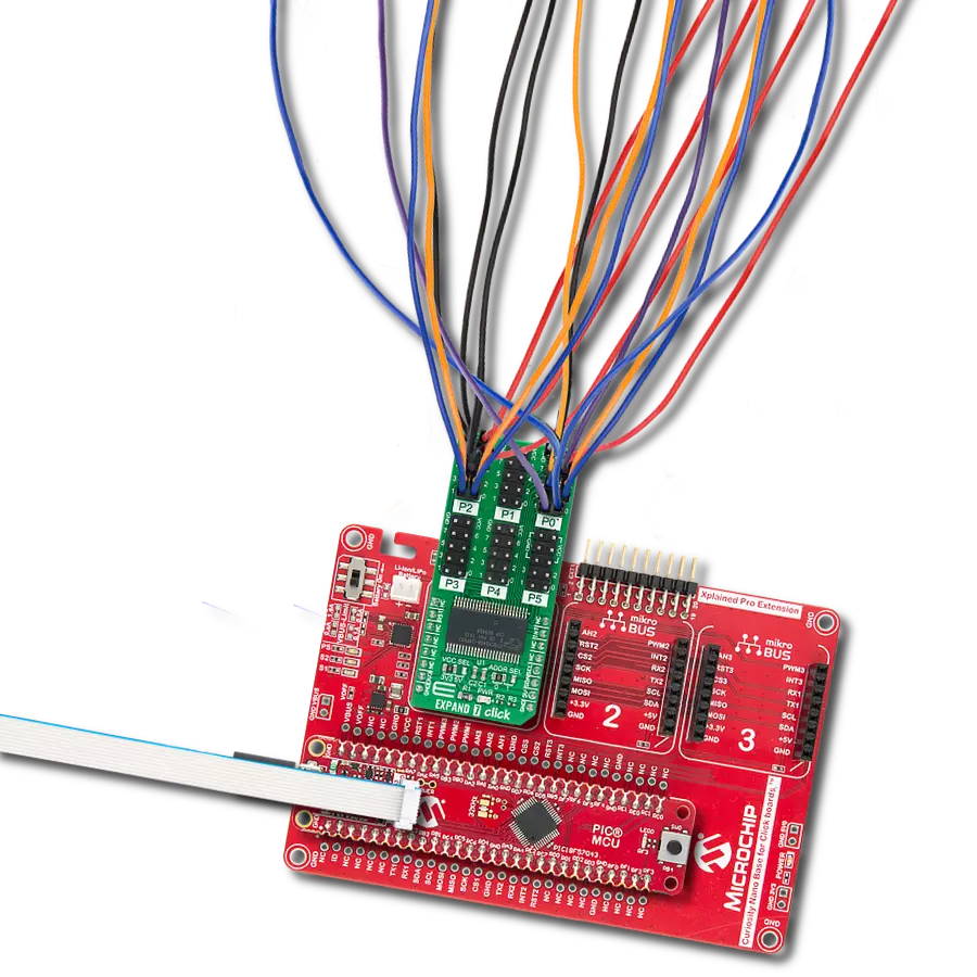
项目组装

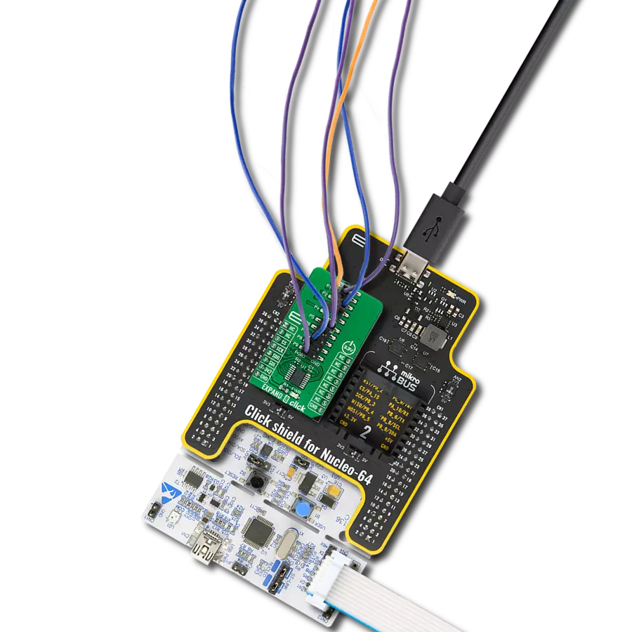
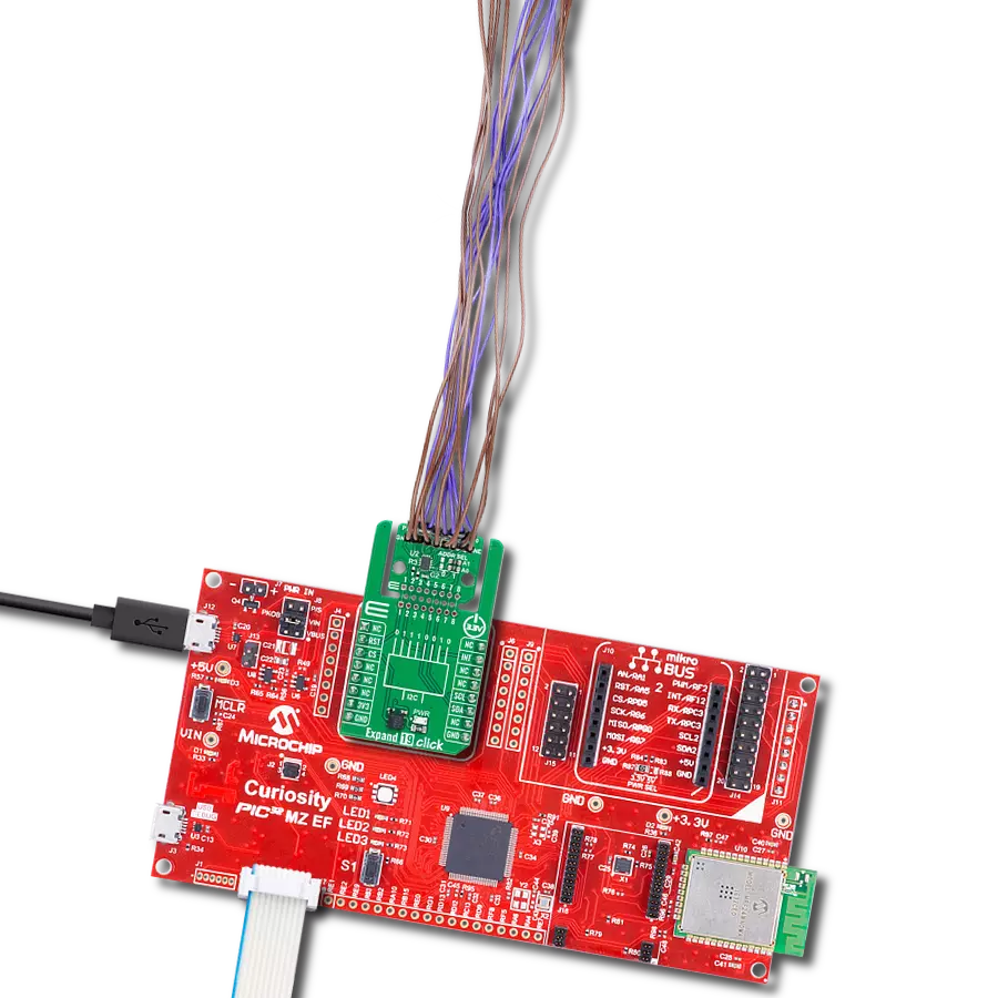
从选择您的开发板和Click板™开始。以Curiosity Nano with PIC18F57Q43作为您的开发板开始。


实时跟踪您的结果
应用程序输出
1. 应用程序输出 - 在调试模式下,“应用程序输出”窗口支持实时数据监控,直接提供执行结果的可视化。请按照提供的教程正确配置环境,以确保数据正确显示。

2. UART 终端 - 使用UART Terminal通过USB to UART converter监视数据传输,实现Click board™与开发系统之间的直接通信。请根据项目需求配置波特率和其他串行设置,以确保正常运行。有关分步设置说明,请参考提供的教程。

3. Plot 输出 - Plot功能提供了一种强大的方式来可视化实时传感器数据,使趋势分析、调试和多个数据点的对比变得更加直观。要正确设置,请按照提供的教程,其中包含使用Plot功能显示Click board™读数的分步示例。在代码中使用Plot功能时,请使用以下函数:plot(insert_graph_name, variable_name);。这是一个通用格式,用户需要将“insert_graph_name”替换为实际图表名称,并将“variable_name”替换为要显示的参数。

软件支持
库描述
该库包含 EXPAND 7 Click 驱动程序的 API。
关键功能:
expand7_reset- 重置功能expand7_write_all- 设置所有输出引脚逻辑电平的功能expand7_write_pin- 设置单个输出引脚逻辑电平的功能
开源
代码示例
完整的应用程序代码和一个现成的项目可以通过NECTO Studio包管理器直接安装到NECTO Studio。 应用程序代码也可以在MIKROE的GitHub账户中找到。
/*!
 * \file
 * \brief Expand7 Click example
 *
 * # Description
 * This example demonstrates the use of the EXPAND 7 Click.
 *
 * The demo application is composed of two sections :
 *
 * ## Application Init
 * Initalizes I2C driver and makes an initial log.
 *
 * ## Application Task
 * This example shows the capabilities of the EXPAND 7 Click by toggling
 * each of the 40 available pins.
 *
 * \author MikroE Team
 *
 */
// ------------------------------------------------------------------- INCLUDES

#include "board.h"
#include "log.h"
#include "expand7.h"

// ------------------------------------------------------------------ VARIABLES

static expand7_t expand7;
static log_t logger;

// ------------------------------------------------------ APPLICATION FUNCTIONS

void application_init ( void )
{
    log_cfg_t log_cfg;
    expand7_cfg_t cfg;

    /**
     * Logger initialization.
     * Default baud rate: 115200
     * Default log level: LOG_LEVEL_DEBUG
     * @note If USB_UART_RX and USB_UART_TX
     * are defined as HAL_PIN_NC, you will
     * need to define them manually for log to work.
     * See @b LOG_MAP_USB_UART macro definition for detailed explanation.
     */
    LOG_MAP_USB_UART( log_cfg );
    log_init( &logger, &log_cfg );
    log_info( &logger, "---- Application Init ----" );

    //  Click initialization.
    expand7_cfg_setup( &cfg );
    EXPAND7_MAP_MIKROBUS( cfg, MIKROBUS_1 );
    expand7_init( &expand7, &cfg );
    Delay_ms ( 100 );

    log_printf( &logger, "------------------- \r\n" );
    log_printf( &logger, "   EXPAND 7 Click   \r\n" );
    log_printf( &logger, "------------------- \r\n" );
}

void application_task ( void )
{
    expand7_write_all ( &expand7, 0xFF );
    log_printf( &logger, "All pins set to HIGH logic level!\r\n" );
    log_printf( &logger, "---------------------------------\r\n" );
    Delay_ms ( 1000 );
    Delay_ms ( 1000 );

    for ( uint8_t pin_num = 0; pin_num < 40; pin_num++ )
    {
        expand7_write_pin( &expand7, pin_num, EXPAND7_LOW );
        log_printf( &logger, "Pin %u is set to LOW logic level!\r\n", ( uint16_t ) pin_num );
        Delay_ms ( 300 );
    }
    log_printf( &logger, "---------------------------------\r\n" );
    Delay_ms ( 1000 );
}

int main ( void )
{
    /* Do not remove this line or clock might not be set correctly. */
    #ifdef PREINIT_SUPPORTED
    preinit();
    #endif

    application_init( );

    for ( ; ; )
    {
        application_task( );
    }

    return 0;
}

// ------------------------------------------------------------------------ END
额外支持
资源
类别:端口扩展器