使用CTHS15CIC05和STM32F031K6轻松控制您的项目
点燃行动!

已发布 10月 01, 2024
点击板
Button Power Click
开发板
Nucleo 32 with STM32F031K6 MCU
编译器
NECTO Studio
微控制器单元
STM32F031K6
通过直观的POWER按钮轻松控制设备状态,提供无缝的开/关功能,以满足您的需求。
A
A
硬件概览
它是如何工作的?
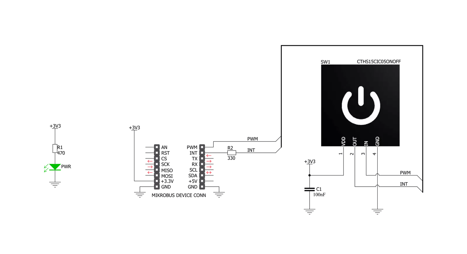
Button Power Click基于VCC(Visual Communications Company)的CTHS15CIC05ONOFF电容式触摸传感器显示器。该传感器是一个一体化解决方案,在顶部提供带背光电源符号图标的电容式触摸感应。该设备使用的引脚最少:用户仅接触到四个引脚。除了电源引脚(VCC和GND)之外,还使用了两个引脚。触摸检测通过CTHS15CIC05ONOFF传感器的OUT引脚上的高逻辑电平来指示,而IN引脚用于两个内部LED的电源供应,这些LED以共阴极配置连接。LED的正向电压通常为3.2V。传感
器的OUT引脚路由到mikroBUS™的INT引脚,而传感器的IN引脚路由到mikroBUS™的PWM引脚。触摸传感器顶部的电源符号图标即使在背光关闭时也能看到,这要归功于放置在传感器顶部的带有反向打印图标的LEXAN™聚碳酸酯薄膜。当内部LED开启时,光线将通过半透明的电源符号图标,使电源符号图标均匀地发光。通过在IN引脚上应用PWM信号,可以设计出有趣的触摸照明效果。传感器IC、感应垫和两个集成LED封装在一个15mm x 15mm x 11mm的小方形外壳中,形成一个紧凑且坚固的触摸按钮,
相对于机械按钮有许多优点:由于没有移动部件,不会磨损,不会出现反弹或抖动效应,耐用且抗天气因素等。然而,它不能用于闭合电路,仅用于产生由主机MCU翻译为适当动作的逻辑信号。传感器即使在湿手或佩戴某些手套的情况下也能操作。触摸传感器还可以放置在高达3mm厚的透明玻璃或塑料层(如聚碳酸酯或丙烯酸)后面。尽管传感器在通电后会进行自校准,但在这些情况下,如果位置固定,最好测试其功能。


功能概述
开发板
Nucleo 32开发板搭载STM32F031K6 MCU,提供了一种经济且灵活的平台,适用于使用32引脚封装的STM32微控制器进行实验。该开发板具有Arduino™ Nano连接性,便于通过专用扩展板进行功能扩展,并且支持mbed,使其能够无缝集成在线资源。板载集成
ST-LINK/V2-1调试器/编程器,支持通过USB重新枚举,提供三种接口:虚拟串口(Virtual Com port)、大容量存储和调试端口。该开发板的电源供应灵活,可通过USB VBUS或外部电源供电。此外,还配备了三个LED指示灯(LD1用于USB通信,LD2用于电源
指示,LD3为用户可控LED)和一个复位按钮。STM32 Nucleo-32开发板支持多种集成开发环境(IDEs),如IAR™、Keil®和基于GCC的IDE(如AC6 SW4STM32),使其成为开发人员的多功能工具。

微控制器概述
MCU卡片 / MCU

建筑
ARM Cortex-M0
MCU 内存 (KB)
32
硅供应商
STMicroelectronics
引脚数
32
RAM (字节)
4096
你完善了我!
配件
Click Shield for Nucleo-32是扩展您的开发板功能的理想选择,专为STM32 Nucleo-32引脚布局设计。Click Shield for Nucleo-32提供了两个mikroBUS™插座,可以添加来自我们不断增长的Click板™系列中的任何功能。从传感器和WiFi收发器到电机控制和音频放大器,我们应有尽有。Click Shield for Nucleo-32与STM32 Nucleo-32开发板兼容,为用户提供了一种经济且灵活的方式,使用任何STM32微控制器快速创建原型,并尝试各种性能、功耗和功能的组合。STM32 Nucleo-32开发板无需任何独立的探针,因为它集成了ST-LINK/V2-1调试器/编程器,并随附STM32全面的软件HAL库和各种打包的软件示例。这个开发平台为用户提供了一种简便且通用的方式,将STM32 Nucleo-32兼容开发板与他们喜欢的Click板™结合,应用于即将开展的项目中。

使用的MCU引脚
mikroBUS™映射器
“仔细看看!”
Click board™ 原理图
一步一步来
项目组装

从选择您的开发板和Click板™开始。以Nucleo 32 with STM32F031K6 MCU作为您的开发板开始。


实时跟踪您的结果
应用程序输出
1. 应用程序输出 - 在调试模式下,“应用程序输出”窗口支持实时数据监控,直接提供执行结果的可视化。请按照提供的教程正确配置环境,以确保数据正确显示。

2. UART 终端 - 使用UART Terminal通过USB to UART converter监视数据传输,实现Click board™与开发系统之间的直接通信。请根据项目需求配置波特率和其他串行设置,以确保正常运行。有关分步设置说明,请参考提供的教程。

3. Plot 输出 - Plot功能提供了一种强大的方式来可视化实时传感器数据,使趋势分析、调试和多个数据点的对比变得更加直观。要正确设置,请按照提供的教程,其中包含使用Plot功能显示Click board™读数的分步示例。在代码中使用Plot功能时,请使用以下函数:plot(insert_graph_name, variable_name);。这是一个通用格式,用户需要将“insert_graph_name”替换为实际图表名称,并将“variable_name”替换为要显示的参数。

软件支持
库描述
此库包含Button Power Click驱动程序的API。
关键功能:
buttonpower_pwm_stop- 此功能停止PWM模块输出。buttonpower_pwm_start- 此功能启动PWM模块输出。buttonpower_get_button_state- 此功能读取来自INT引脚的数字信号,以判断按钮是否被按下。
开源
代码示例
完整的应用程序代码和一个现成的项目可以通过NECTO Studio包管理器直接安装到NECTO Studio。 应用程序代码也可以在MIKROE的GitHub账户中找到。
/*!
 * @file main.c
 * @brief Button Power Click Example.
 *
 * # Description
 * This example showcases how to initialize and use the whole family of Button clicks.
 * One library is used for every single one of them. They are simple touch detectors which send
 * a pressed/released signal and receive a PWM output which controls the backlight on the button.
 *
 * The demo application is composed of two sections :
 *
 * ## Application Init
 * This function initializes and configures the logger and click modules.
 *
 * ## Application Task
 * This example first increases the backlight on the button and then decreases the intensity of the backlight. When the button is touched,
 * reports the event in the console using UART communication.
 *
 *
 * @author Nikola Peric
 *
 */

#include "board.h"
#include "log.h"
#include "buttonpower.h"

static buttonpower_t buttonpower;
static log_t logger;

void application_init ( void )
{
    log_cfg_t log_cfg;                   /**< Logger config object. */
    buttonpower_cfg_t buttonpower_cfg;   /**< Click config object. */

    /**
     * Logger initialization.
     * Default baud rate: 115200
     * Default log level: LOG_LEVEL_DEBUG
     * @note If USB_UART_RX and USB_UART_TX
     * are defined as HAL_PIN_NC, you will
     * need to define them manually for log to work.
     * See @b LOG_MAP_USB_UART macro definition for detailed explanation.
     */
    LOG_MAP_USB_UART( log_cfg );
    log_init( &logger, &log_cfg );
    log_info( &logger, " Application Init " );

    // Click initialization.

    buttonpower_cfg_setup( &buttonpower_cfg );
    BUTTONPOWER_MAP_MIKROBUS( buttonpower_cfg, MIKROBUS_1 );
    err_t init_flag  = buttonpower_init( &buttonpower, &buttonpower_cfg );
    if ( PWM_ERROR == init_flag )
    {
        log_error( &logger, " Application Init Error. " );
        log_info( &logger, " Please, run program again... " );

        for ( ; ; );
    }
    Delay_ms( 500 );

    buttonpower_pwm_start( &buttonpower );
    buttonpower_set_duty_cycle ( &buttonpower, 0.1 );

    log_info( &logger, " Application Task " );
}

void application_task ( void )
{
    static float duty_cycle;
    static uint8_t button_state;
    static uint8_t button_state_old;

    button_state = buttonpower_get_button_state( &buttonpower );

    if ( button_state && ( button_state != button_state_old ) )
    {
        log_printf( &logger, " <-- Button pressed --> \r\n" );
        for ( uint8_t n_cnt = 1; n_cnt <= 100; n_cnt++ )
        {
            duty_cycle = ( float ) n_cnt ;
            duty_cycle /= 100;
            buttonpower_set_duty_cycle( &buttonpower, duty_cycle );
            Delay_ms( 10 );
        }
        button_state_old = button_state;
    }
    else if ( !button_state && ( button_state != button_state_old ) )
    {
        for ( uint8_t n_cnt = 100; n_cnt > 0; n_cnt-- )
        {
            duty_cycle = ( float ) n_cnt ;
            duty_cycle /= 100;
            buttonpower_set_duty_cycle( &buttonpower, duty_cycle );
            Delay_ms( 10 );
        }
        button_state_old = button_state;
    }
}

void main ( void )
{
    application_init( );

    for ( ; ; )
    {
        application_task( );
    }
}

// ------------------------------------------------------------------------ END
额外支持
资源
类别:电容


