使用INA228和STM32G431RB实现最高精度的电源监控
重新定义电源洞察:通过超精确监控提升性能
已发布 11月 08, 2024
点击板
Power Monitor Click
开发板
Nucleo 64 with STM32G431RB MCU
编译器
NECTO Studio
微控制器单元
STM32G431RB
我们的超精密电力监控解决方案重新定义了您对电力使用情况的洞察,提供无与伦比的准确性,以优化性能、降低成本并确保系统的可靠性。
A
A
硬件概览
它是如何工作的?
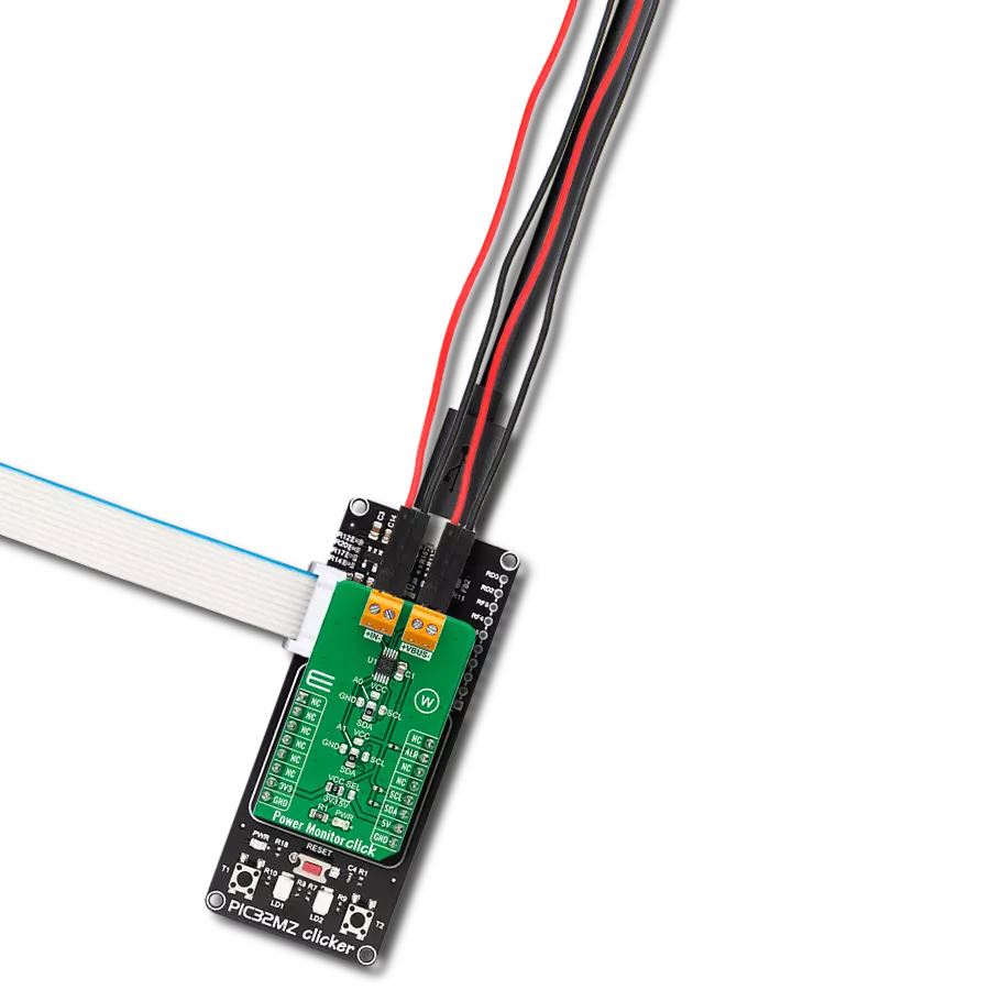
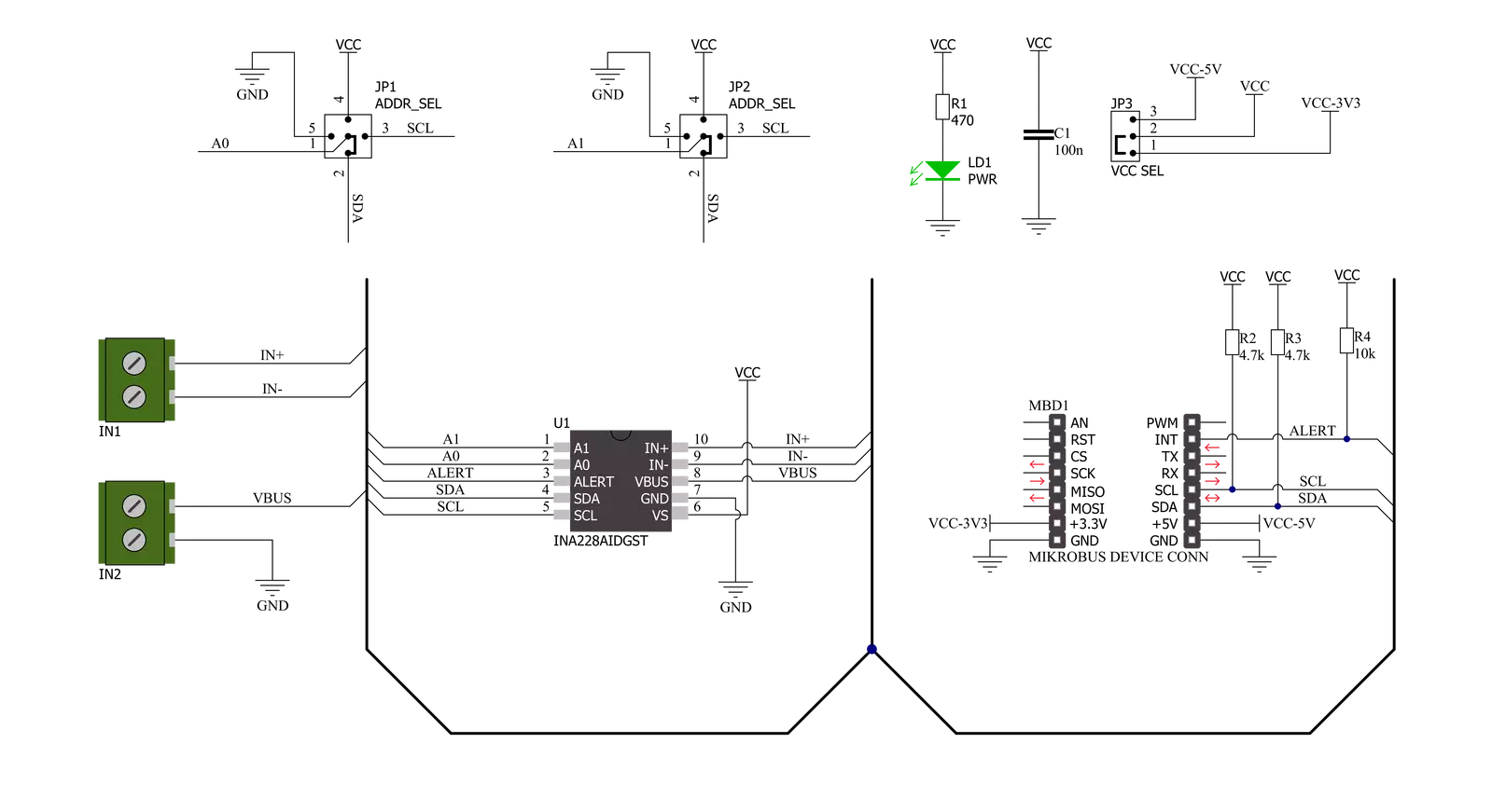
Power Monitor Click基于INA228,这是一款超精密的数字电源监控器,采用德州仪器的20位Delta-Sigma ADC和I2C数字接口。它测量分流电压、总线电压和内部温度,同时计算电流、功率、能量和电荷,为精确控制系统中的准确决策提供必要的数据。它可以测量通过接在板载IN端子上的电阻分流传感元件的±163.84mV或±40.96mV的满量程差分输入,支持高达+85V的共模电压,使其适合高侧和低侧电流测量。INA228还通过VBUS端子测量总线电压,并通过集成的±1°C精度温度传感器测量温度,帮助监控环境系统温度。功率、电荷和能量的计算在后台进行,不会增加整体ADC转换时
间。此外,非常低的偏置电压和噪声使其可用于毫安到千安的传感应用,并提供宽动态范围,而不会在传感分流元件上产生显著的功耗损失。Power Monitor Click通过标准的I2C 2线接口与MCU通信,以读取数据和配置设置,支持高达400kHz的快速模式操作。INA228还允许通过两个标记为A0和A1的SMD十字形跳线选择其I2C从属地址。一个十字形跳线有四个位置可选择地址引脚,可连接到GND、VS、SCL或SDA引脚。通过将SMD跳线定位到适当的位置,INA228提供了16个不同I2C地址的选择机会。此外,INA228还包括多功能警报(中断)引脚,标记为ALR并路由到mikroBUS™插座的
INT引脚,用于在设备在触发和连续转换模式下操作时,报告多个诊断或作为ADC转换完成的指示。当监控的输出值越过其相关的超范围阈值时,诸如分流过/欠电压限制、总线过/欠电压限制或温度或功率过限等诊断会通过ALR引脚不断监控和报告。此Click板™可通过VCC SEL跳线选择3.3V或5V逻辑电压电平,从而使具有3.3V和5V能力的MCU能够正确使用通信线路。此外,该Click板™配备了一个包含易于使用的函数和示例代码的库,可作为进一步开发的参考。

功能概述
开发板
Nucleo-64 搭载 STM32G431RB MCU 提供了一种经济高效且灵活的平台,供开发者探索新想法并原型设计他们的项目。该板利用 STM32 微控制器的多功能性,使用户能够为他们的项目选择最佳的性能与功耗平衡。它配备了 LQFP64 封装的 STM32 微控制器,并包含了如用户 LED(同时作为 ARDUINO® 信号)、用户和复位按钮,以及 32.768kHz 晶体振荡器用于精确的计时操作等基本组件。Nucleo-64 板设计考虑到扩展性和灵活性,它特有的 ARDUINO® Uno
V3 扩展连接器和 ST morpho 扩展引脚头,提供了对 STM32 I/O 的完全访问,以实现全面的项目整合。电源供应选项灵活,支持 ST-LINK USB VBUS 或外部电源,确保在各种开发环境中的适应性。该板还配备了一个具有 USB 重枚举功能的板载 ST-LINK 调试器/编程器,简化了编程和调试过程。此外,该板设计旨在简化高级开发,它的外部 SMPS 为 Vcore 逻辑供电提供高效支持,支持 USB 设备全速或 USB SNK/UFP 全速,并内置加密功能,提升了项目的功效
和安全性。通过外部 SMPS 实验的专用连接器、 用于 ST-LINK 的 USB 连接器以及 MIPI® 调试连接器,提供了更多的硬件接口和实验可能性。开发者将通过 STM32Cube MCU Package 提供的全面免费软件库和示例得到广泛支持。这些,加上与多种集成开发环境(IDE)的兼容性,包括 IAR Embedded Workbench®、MDK-ARM 和 STM32CubeIDE,确保了流畅且高效的开发体验,使用户能够充分利用 Nucleo-64 板在他们的项目中的能力。

微控制器概述
MCU卡片 / MCU
建筑
ARM Cortex-M4
MCU 内存 (KB)
128
硅供应商
STMicroelectronics
引脚数
64
RAM (字节)
32k
你完善了我!
配件
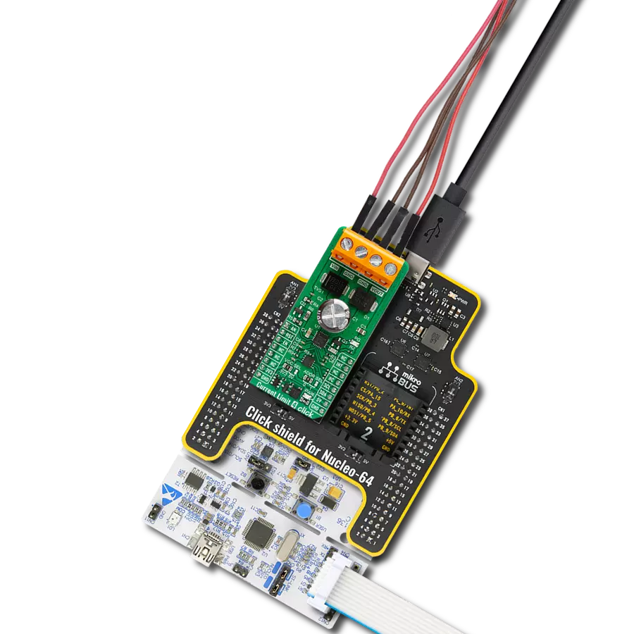
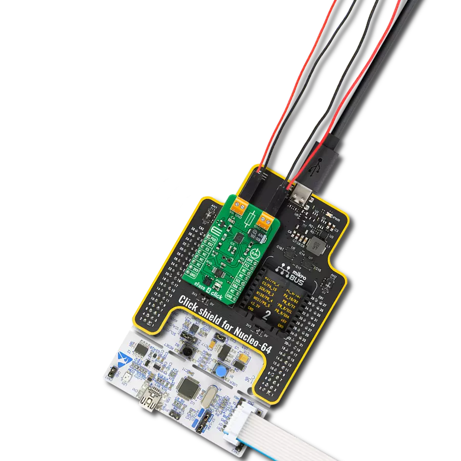
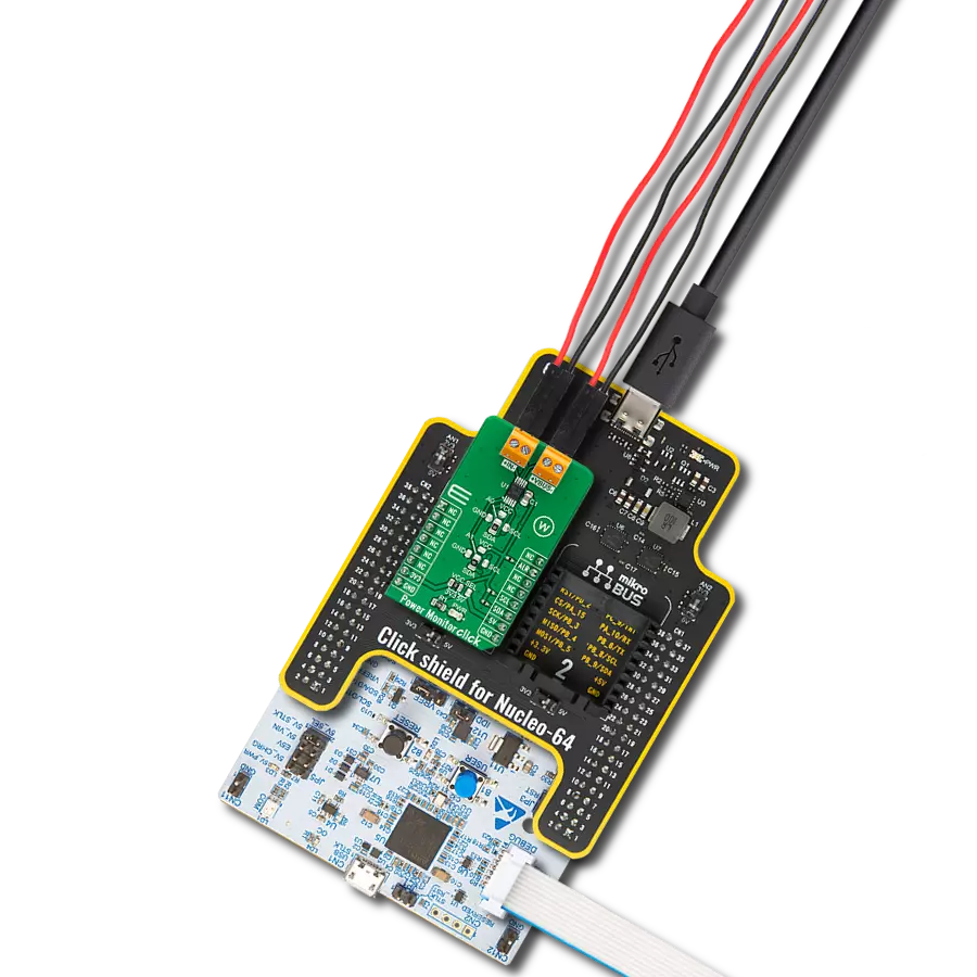
Click Shield for Nucleo-64 配备了两个专有的 mikroBUS™ 插座,使得所有的 Click board™ 设备都可以轻松地与 STM32 Nucleo-64 开发板连接。这样,Mikroe 允许其用户从不断增长的 Click boards™ 范围中添加任何功能,如 WiFi、GSM、GPS、蓝牙、ZigBee、环境传感器、LED、语音识别、电机控制、运动传感器等。您可以使用超过 1537 个 Click boards™,这些 Click boards™ 可以堆叠和集成。STM32 Nucleo-64 开发板基于 64 引脚封装的微控制器,采用 32 位 MCU,配备 ARM Cortex M4 处理器,运行速度为 84MHz,具有 512Kb Flash 和 96KB SRAM,分为两个区域,顶部区域代表 ST-Link/V2 调试器和编程器,而底部区域是一个实际的开发板。通过 USB 连接方便地控制和供电这些板子,以便直接对 Nucleo-64 开发板进行编程和高效调试,其中还需要额外的 USB 线连接到板子上的 USB 迷你接口。大多数 STM32 微控制器引脚都连接到了板子左右边缘的 IO 引脚上,然后连接到两个现有的 mikroBUS™ 插座上。该 Click Shield 还有几个开关,用于选择 mikroBUS™ 插座上模拟信号的逻辑电平和 mikroBUS™ 插座本身的逻辑电压电平。此外,用户还可以通过现有的双向电平转换器,使用任何 Click board™,无论 Click board™ 是否在 3.3V 或 5V 逻辑电压电平下运行。一旦将 STM32 Nucleo-64 开发板与我们的 Click Shield for Nucleo-64 连接,您就可以访问数百个工作于 3.3V 或 5V 逻辑电压电平的 Click boards™。

使用的MCU引脚
mikroBUS™映射器
“仔细看看!”
Click board™ 原理图
一步一步来
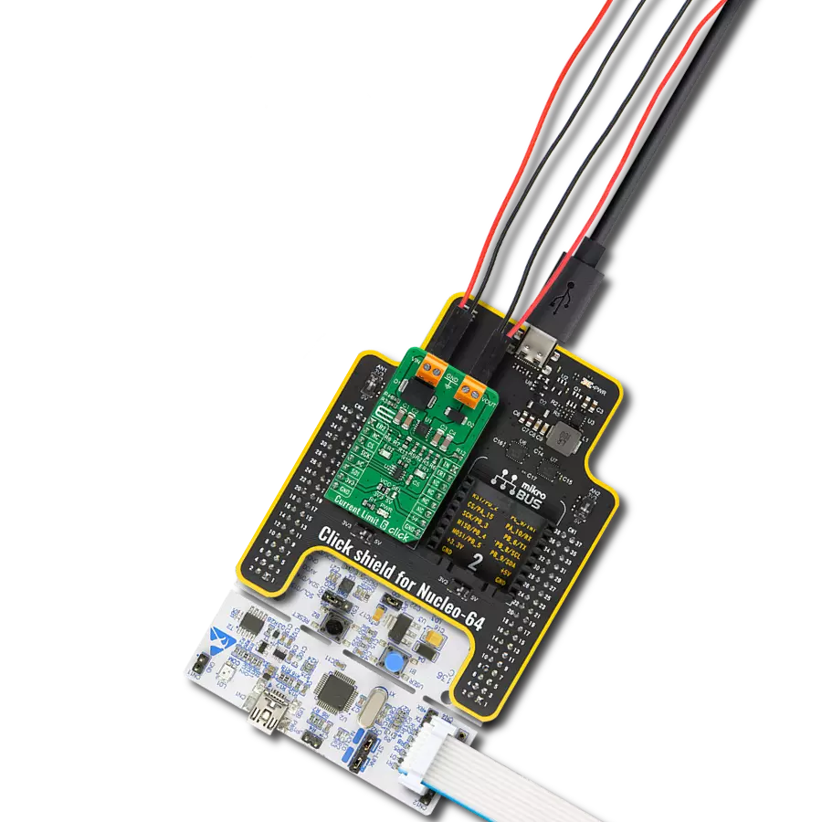
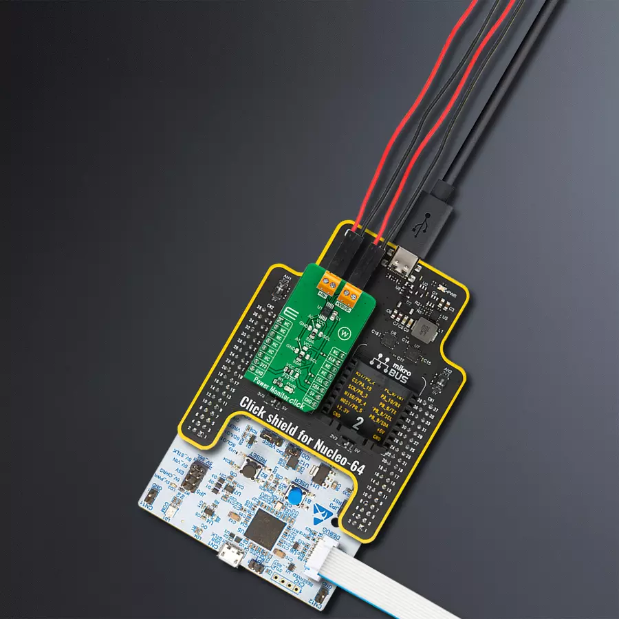
项目组装
从选择您的开发板和Click板™开始。以Nucleo 64 with STM32G431RB MCU作为您的开发板开始。


软件支持
库描述
该库包含 Power Monitor Click 驱动程序的 API。
关键功能:
powermonitor_get_vshunt- 电力监控获取分流电压功能powermonitor_get_vbus- 电力监控获取总线电压功能powermonitor_get_current- 电力监控获取电流功能
开源
代码示例
完整的应用程序代码和一个现成的项目可以通过NECTO Studio包管理器直接安装到NECTO Studio。 应用程序代码也可以在MIKROE的GitHub账户中找到。
/*!
* @file main.c
* @brief PowerMonitor Click example
*
* # Description
* This library contains API for Power Monitor Click driver.
* The library initializes and defines the I2C bus drivers
* to write and read data from registers.
* The library also includes a function for reading
* Shunt and Bus voltage ( mV ), Current ( mA ), Power ( W ), Energy ( J ),
* as well as the Temperature in degrees Celsius.
*
* The demo application is composed of two sections :
*
* ## Application Init
* The initialization of I2C module, log UART, and additional pins.
* After the driver init and then executes a default configuration,
* the app checks communication, display Manufacturer, Stores Device and Revision ID.
*
* ## Application Task
* This is an example that shows the use of a Power Monitor Click board™.
* Measures and displays Shunt voltage ( mV ), Bus voltage ( mV ),
* Current ( mA ), Power ( W ), Energy ( J ) and Temperature ( degrees Celsius ).
* Results are being sent to the USART terminal where the user can track their changes.
* This task repeats every 2.5 sec.
*
* @author Nenad Filipovic
*
*/
#include "board.h"
#include "log.h"
#include "powermonitor.h"
static powermonitor_t powermonitor;
static log_t logger;
void application_init ( void )
{
log_cfg_t log_cfg; /**< Logger config object. */
powermonitor_cfg_t powermonitor_cfg; /**< Click config object. */
static uint8_t manufacturer_id[ 2 ];
static uint16_t dieid;
static uint8_t rev_id;
powermonitor.shunt = 0.28;
/**
* Logger initialization.
* Default baud rate: 115200
* Default log level: LOG_LEVEL_DEBUG
* @note If USB_UART_RX and USB_UART_TX
* are defined as HAL_PIN_NC, you will
* need to define them manually for log to work.
* See @b LOG_MAP_USB_UART macro definition for detailed explanation.
*/
LOG_MAP_USB_UART( log_cfg );
log_init( &logger, &log_cfg );
log_info( &logger, " Application Init " );
// Click initialization.
powermonitor_cfg_setup( &powermonitor_cfg );
POWERMONITOR_MAP_MIKROBUS( powermonitor_cfg, MIKROBUS_1 );
err_t init_flag = powermonitor_init( &powermonitor, &powermonitor_cfg );
if ( I2C_MASTER_ERROR == init_flag )
{
log_error( &logger, " Application Init Error. " );
log_info( &logger, " Please, run program again... " );
for ( ; ; );
}
powermonitor_default_cfg ( &powermonitor );
log_printf( &logger, "----------------------------\r\n" );
Delay_ms ( 100 );
powermonitor_get_id( &powermonitor, &manufacturer_id, &dieid, &rev_id );
log_printf( &logger, " Manufacturer ID : %.2s\r\n", manufacturer_id );
log_printf( &logger, " Stores Device ID : 0x%.3X\r\n", dieid );
log_printf( &logger, " Revision ID : 0x%.1X\r\n", rev_id );
log_printf( &logger, "----------------------------\r\n" );
log_info( &logger, " Application Task " );
log_printf( &logger, "----------------------------\r\n" );
Delay_ms ( 100 );
}
void application_task ( void )
{
static float vshunt, vbus, current, power, energy, temperature;
powermonitor_get_vshunt( &powermonitor, &vshunt );
log_printf( &logger, " Shunt voltage : %.2f mV\r\n", vshunt );
Delay_ms ( 100 );
powermonitor_get_vbus( &powermonitor, &vbus );
log_printf( &logger, " BUS voltage : %.2f mV\r\n", vbus );
Delay_ms ( 100 );
powermonitor_get_current( &powermonitor, ¤t );
log_printf( &logger, " Current : %.2f mA\r\n", current );
Delay_ms ( 100 );
powermonitor_get_power( &powermonitor, &power );
log_printf( &logger, " Power : %.6f W\r\n", power );
Delay_ms ( 100 );
powermonitor_get_energy( &powermonitor, &energy );
log_printf( &logger, " Energy : %.6f J\r\n", energy );
log_printf( &logger, "- - - - - - - - - - - - - - \r\n" );
Delay_ms ( 100 );
powermonitor_get_temperature( &powermonitor, &temperature );
log_printf( &logger, " Temperature : %.2f C\r\n", temperature );
log_printf( &logger, "----------------------------\r\n" );
Delay_ms ( 1000 );
Delay_ms ( 1000 );
}
int main ( void )
{
/* Do not remove this line or clock might not be set correctly. */
#ifdef PREINIT_SUPPORTED
preinit();
#endif
application_init( );
for ( ; ; )
{
application_task( );
}
return 0;
}
// ------------------------------------------------------------------------ END
额外支持
资源
类别:电源开关