Create general-purpose data selector with TMUX1308 and PIC32MZ1024EFH064
Analog multiplexer
Published Mar 06, 2023
Click board™
Analog MUX 4 Click
Dev. board
PIC32MZ clicker
Compiler
NECTO Studio
MCU
PIC32MZ1024EFH064
Choose one of many analog data inputs
A
A
Hardware Overview
How does it work?
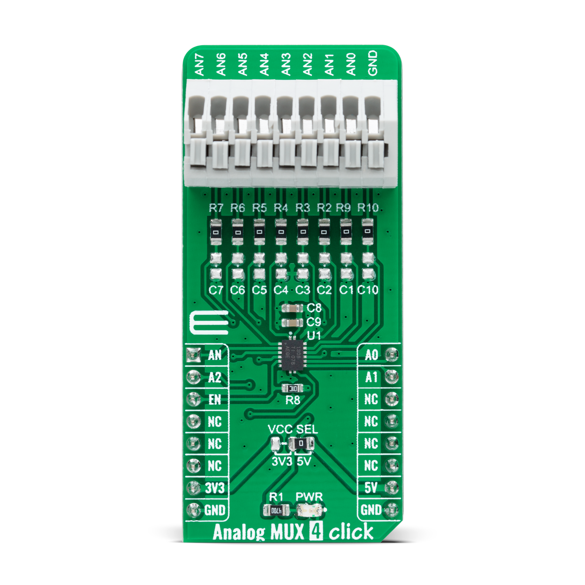
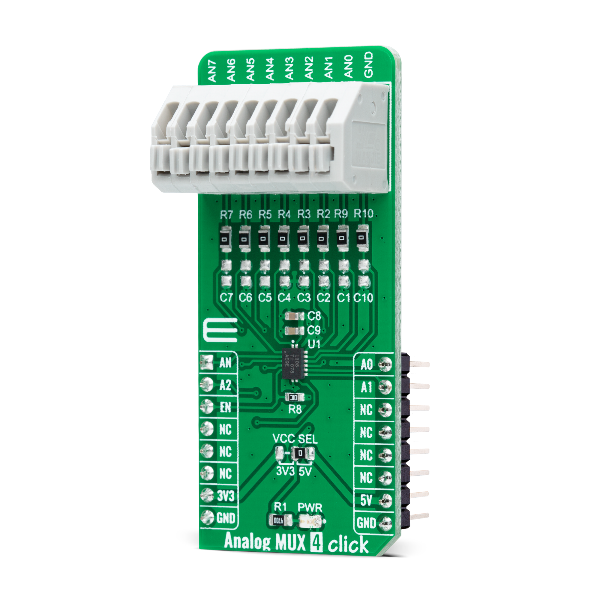
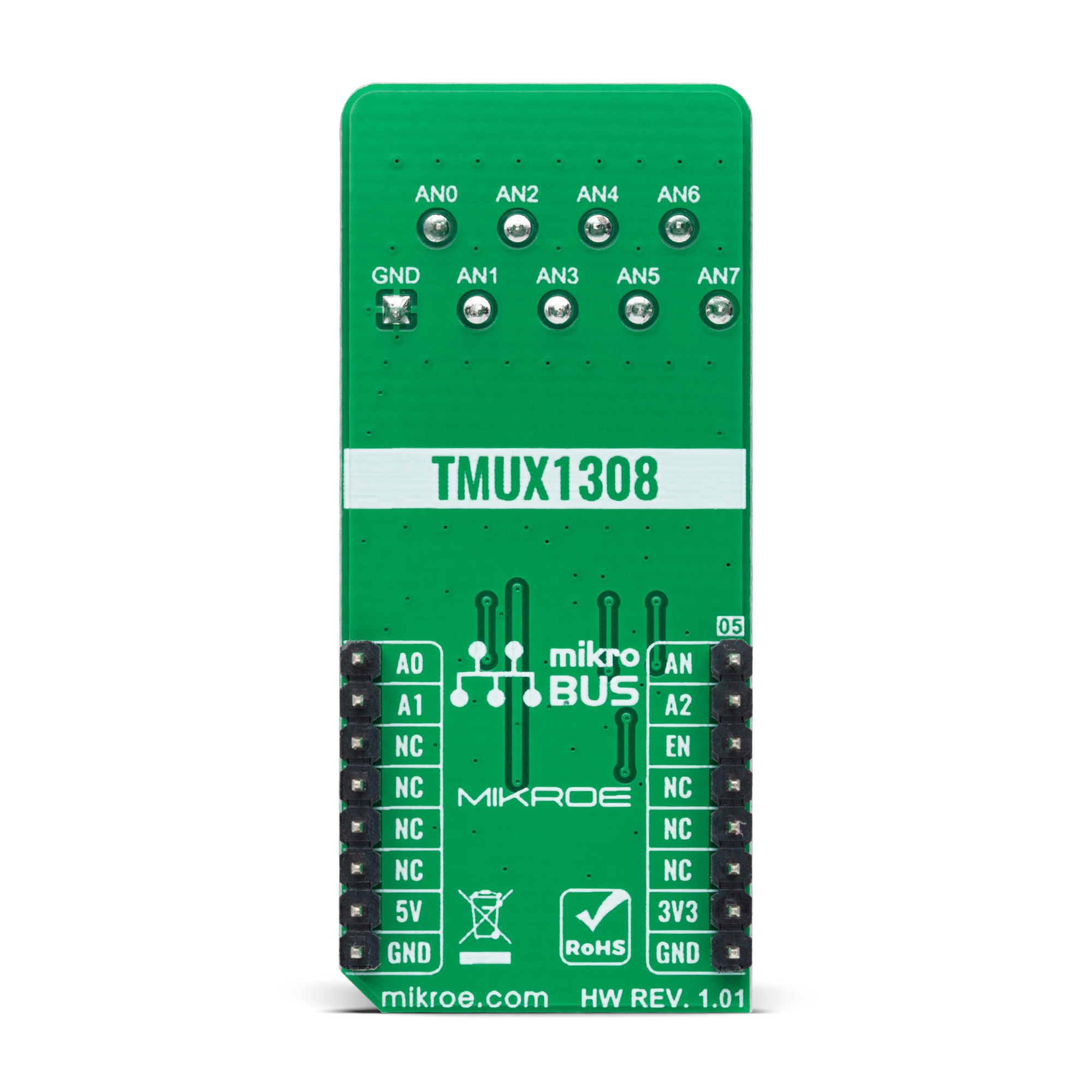
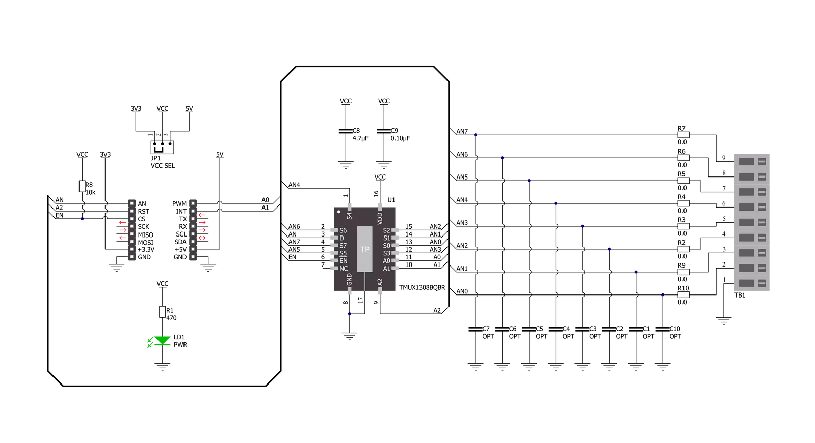
Analog MUX 4 Click is based on the TMUX1308, a general-purpose 8:1 single-ended CMOS analog multiplexer from Texas Instruments. The TMUX1308 multiplexer allows for multiple inputs/sensors to be monitored with a single AN pin of the mikroBUS™ socket supporting bidirectional analog and digital signals ranging from 0 to 5V. It has an internal injection current control eliminating the need for external diode and resistor networks to protect the switch, keeping the input signals within the supply voltage. The internal injection current control circuitry allows signals on disabled signal paths to exceed the supply voltage without affecting the signal of the enabled signal path.
Alongside internal injection current control, the TMUX1308 also has another protection feature, called Break-before-make delay, which represents a safety feature preventing two inputs from connecting when the device is switching. The output first breaks from the ON-state switch before connecting with the next ON-state switch. This time delay between the break and the make is known as the break-before-make delay. This Click board™ communicates with MCU using several GPIO pins. It can be enabled or disabled through the EN pin of the mikroBUS™ socket, hence, offering a switch operation to turn ON/OFF power delivery to the TMUX1308. It also provides three address signals, labeled from A0 to A2, that control
the switch configuration and determine the activation of the desired analog input channel based on their setup. Also, each analog input has a jumper for its hardware activation or deactivation and capacitors for additional filtering of the input channels. This Click board™ can operate with either 3.3V or 5V logic voltage levels selected via the VCC SEL jumper. This way, both 3.3V and 5V capable MCUs can use the communication lines properly. However, the Click board™ comes equipped with a library containing easy-to-use functions and an example code that can be used, as a reference, for further development.
Features overview
Development board
PIC32MZ Clicker is a compact starter development board that brings the flexibility of add-on Click boards™ to your favorite microcontroller, making it a perfect starter kit for implementing your ideas. It comes with an onboard 32-bit PIC32MZ microcontroller with FPU from Microchip, a USB connector, LED indicators, buttons, a mikroProg connector, and a header for interfacing with external electronics. Thanks to its compact design with clear and easy-recognizable silkscreen markings, it provides a fluid and immersive working experience, allowing access anywhere and under
any circumstances. Each part of the PIC32MZ Clicker development kit contains the components necessary for the most efficient operation of the same board. In addition to the possibility of choosing the PIC32MZ Clicker programming method, using USB HID mikroBootloader, or through an external mikroProg connector for PIC, dsPIC, or PIC32 programmer, the Clicker board also includes a clean and regulated power supply module for the development kit. The USB Micro-B connection can provide up to 500mA of current, which is more than enough to operate all onboard
and additional modules. All communication methods that mikroBUS™ itself supports are on this board, including the well-established mikroBUS™ socket, reset button, and several buttons and LED indicators. PIC32MZ Clicker is an integral part of the Mikroe ecosystem, allowing you to create a new application in minutes. Natively supported by Mikroe software tools, it covers many aspects of prototyping thanks to a considerable number of different Click boards™ (over a thousand boards), the number of which is growing every day.

Microcontroller Overview
MCU Card / MCU

Architecture
PIC32
MCU Memory (KB)
1024
Silicon Vendor
Microchip
Pin count
64
RAM (Bytes)
524288
Used MCU Pins
mikroBUS™ mapper
Take a closer look
Click board™ Schematic
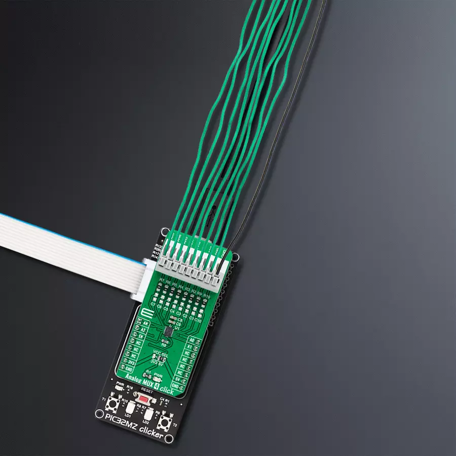
Step by step
Project assembly

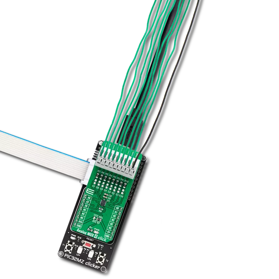
Start by selecting your development board and Click board™. Begin with the PIC32MZ clicker as your development board.


Software Support
Library Description
This library contains API for Analog MUX 4 Click driver.
Key functions:
analogmux4_enable_inputThis function enables analog inputs.analogmux4_read_an_pin_voltageThis function reads the results of the AD conversion of the AN pin and converts them to a proportional voltage level.analogmux4_set_input_channelThis function sets the analog input channel.
Open Source
Code example
The complete application code and a ready-to-use project are available through the NECTO Studio Package Manager for direct installation in the NECTO Studio. The application code can also be found on the MIKROE GitHub account.
/*!
 * @file main.c
 * @brief Analog MUX 4 Click Example.
 *
 * # Description
 * This example demonstrates the use of Analog MUX 4 Click board.
 *
 * The demo application is composed of two sections :
 *
 * ## Application Init
 * Initializes the driver and enables the analog inputs.
 *
 * ## Application Task
 * Reads and displays the voltage of all channels on the USB UART approximately once per second.
 *
 * @note
 * The channel's voltage will "float" when the voltage source is not connected to it.
 *
 * @author Stefan Filipovic
 *
 */

#include "board.h"
#include "log.h"
#include "analogmux4.h"

static analogmux4_t analogmux4;   /**< Analog MUX 4 Click driver object. */
static log_t logger;              /**< Logger object. */

void application_init ( void )
{
    log_cfg_t log_cfg;                /**< Logger config object. */
    analogmux4_cfg_t analogmux4_cfg;  /**< Click config object. */

    /**
     * Logger initialization.
     * Default baud rate: 115200
     * Default log level: LOG_LEVEL_DEBUG
     * @note If USB_UART_RX and USB_UART_TX
     * are defined as HAL_PIN_NC, you will
     * need to define them manually for log to work.
     * See @b LOG_MAP_USB_UART macro definition for detailed explanation.
     */
    LOG_MAP_USB_UART( log_cfg );
    log_init( &logger, &log_cfg );
    log_info( &logger, " Application Init " );

    // Click initialization.
    analogmux4_cfg_setup( &analogmux4_cfg );
    ANALOGMUX4_MAP_MIKROBUS( analogmux4_cfg, MIKROBUS_1 );
    if ( ADC_ERROR == analogmux4_init( &analogmux4, &analogmux4_cfg ) )
    {
        log_error( &logger, " Application Init Error. " );
        log_info( &logger, " Please, run program again... " );

        for ( ; ; );
    }

    analogmux4_enable_input ( &analogmux4 );
    log_info( &logger, " Application Task " );
}

void application_task ( void )
{
    float analogmux4_an_voltage = 0;

    for ( uint8_t cnt = ANALOGMUX4_CHANNEL_0; cnt <= ANALOGMUX4_CHANNEL_7; cnt++ )
    {
        analogmux4_set_input_channel ( &analogmux4, cnt );
        if ( ADC_ERROR != analogmux4_read_an_pin_voltage ( &analogmux4, &analogmux4_an_voltage ) )
        {
            log_printf( &logger, " AN%u voltage : %.3f V\r\n", ( uint16_t ) cnt, analogmux4_an_voltage );
        }
    }
    log_printf( &logger, "\r\n" );
    Delay_ms ( 1000 );
}

int main ( void )
{
    /* Do not remove this line or clock might not be set correctly. */
    #ifdef PREINIT_SUPPORTED
    preinit();
    #endif

    application_init( );

    for ( ; ; )
    {
        application_task( );
    }

    return 0;
}

// ------------------------------------------------------------------------ END
Additional Support
Resources
Category:Port expander


