Enhance your design with NFC Tag technology by using M24LR64E-R and PIC32MZ1024EFH064
Quick exchange of a digitized information

Published Mar 03, 2023
Click board™
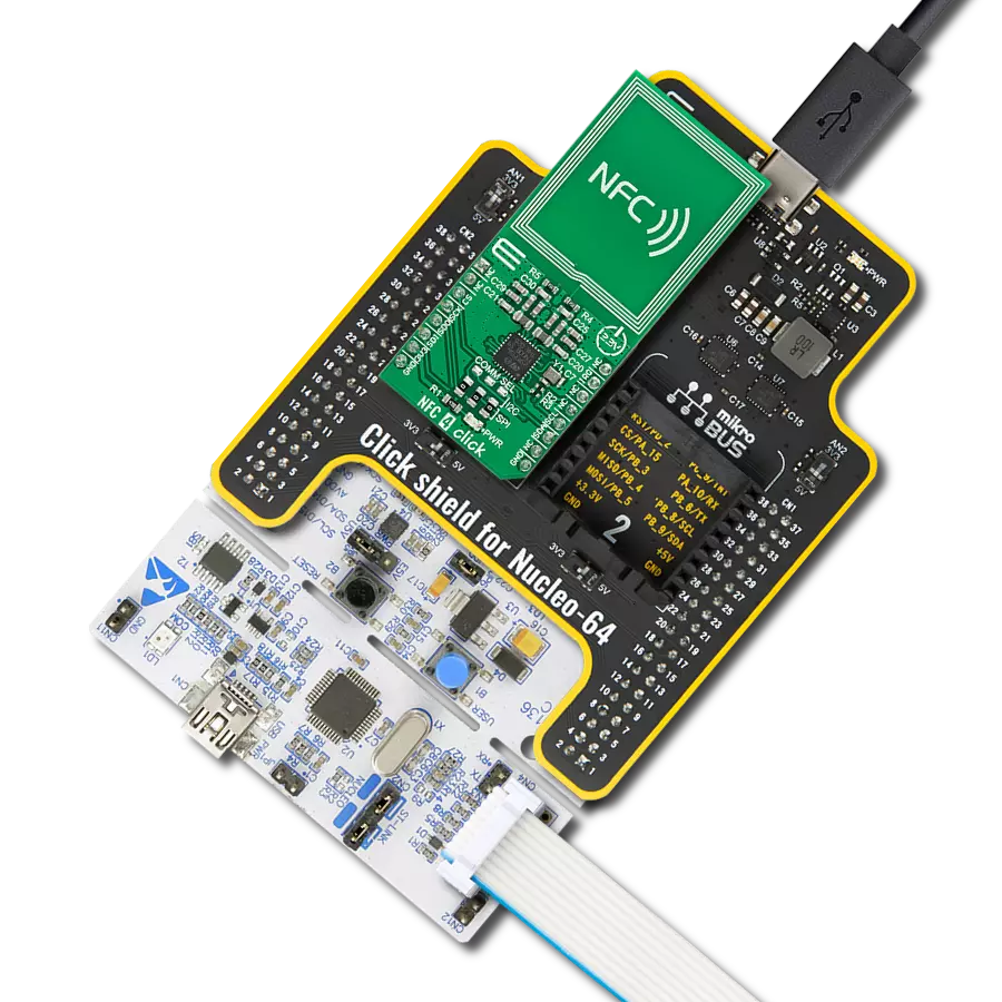
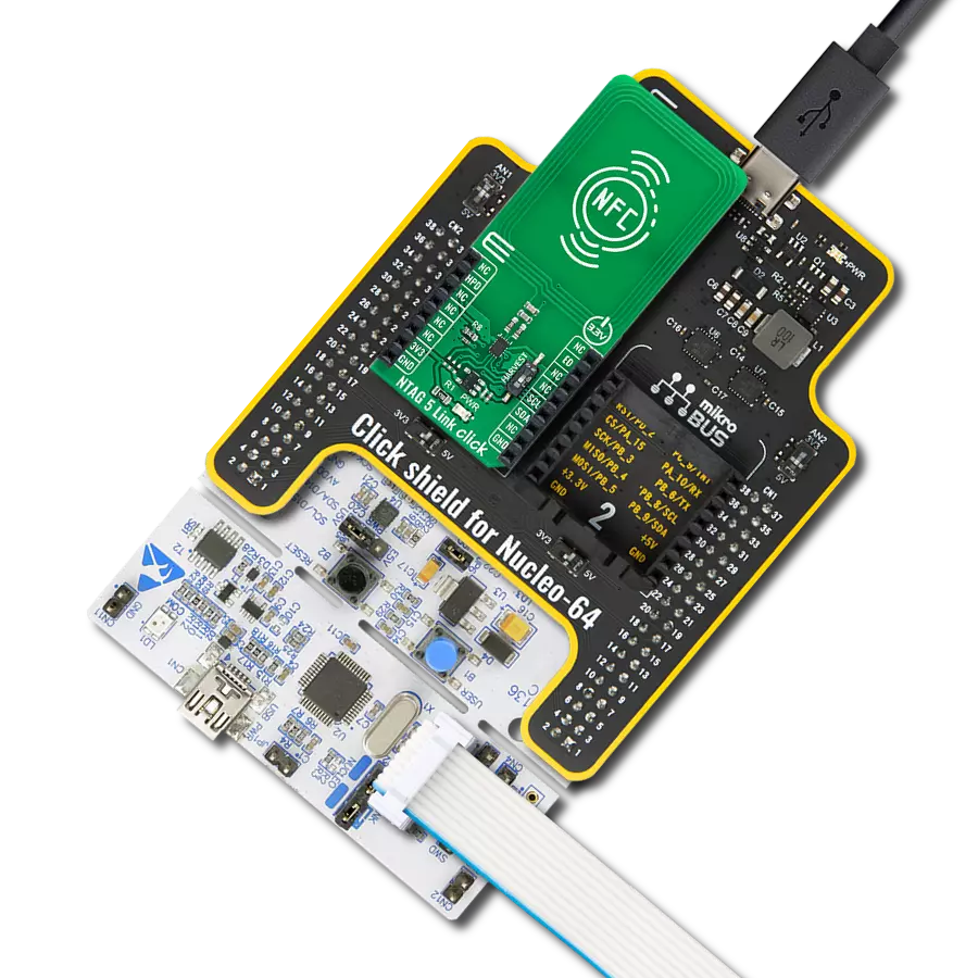
NFC Tag 5 Click
Dev. board
PIC32MZ clicker
Compiler
NECTO Studio
MCU
PIC32MZ1024EFH064
Transfer data using short-range RF communication
A
A
Hardware Overview
How does it work?
NFC Tag 5 Click is based on the M24LR64E-R, a 64-Kbit dynamic NFC/RFID tag with password protection, energy harvesting, and RF status functions from STMicroelectronics. This highly integrated Near Field Communication tag module comes with a dual-interface electrically erasable programmable memory (EEPROM), an I2C interface alongside an RF contactless interface operating at 13.56MHz, organized as 8192×8 bits in the I2C mode and 2048×32 bits in the ISO 15693 and ISO 18000-3 mode 1 RF mode. This Click board™ contains the properly tuned integrated trace antenna on the PCB to power and access the device using the ISO/IEC 15693 and ISO 18000-3 mode one protocol. Power is transferred to the M24LR64E-R by radio frequency at 13.56MHz via
coupling antennas. As mentioned, this Click board™ communicates with MCU using the standard I2C 2-Wire interface with a maximum clock frequency of 400kHz, fully adjustable through software registers. It also provides an Energy harvesting mode on the analog pin of the mikroBUS™ socket marked as VH. When the Energy harvesting mode is activated, the M24LR64E-R can output the excess energy from the RF field on the VH pin. If the RF field strength is insufficient or when the Energy harvesting mode is disabled, the VH pin goes into a high-Z state, and the Energy harvesting mode is automatically stopped. Besides, it also features a user-configurable pin marked as BSY, routed to the AN analog pin of the mikroBUS™ socket, used either to indicate that the
M24LR64E-R is executing an internal write cycle from the RF channel or that an RF command is in progress. When configured in the RF write in progress mode, the BSY pin is driven low for the entire RF internal write operation duration. When configured in the RF busy mode, this pin is driven low for the whole period of the RF command progress. This Click board™ can operate with either 3.3V or 5V logic voltage levels selected via the VCC SEL jumper. This way, both 3.3V and 5V capable MCUs can use the communication lines properly. However, the Click board™ comes equipped with a library containing easy-to-use functions and an example code that can be used, as a reference, for further development.


Features overview
Development board
PIC32MZ Clicker is a compact starter development board that brings the flexibility of add-on Click boards™ to your favorite microcontroller, making it a perfect starter kit for implementing your ideas. It comes with an onboard 32-bit PIC32MZ microcontroller with FPU from Microchip, a USB connector, LED indicators, buttons, a mikroProg connector, and a header for interfacing with external electronics. Thanks to its compact design with clear and easy-recognizable silkscreen markings, it provides a fluid and immersive working experience, allowing access anywhere and under
any circumstances. Each part of the PIC32MZ Clicker development kit contains the components necessary for the most efficient operation of the same board. In addition to the possibility of choosing the PIC32MZ Clicker programming method, using USB HID mikroBootloader, or through an external mikroProg connector for PIC, dsPIC, or PIC32 programmer, the Clicker board also includes a clean and regulated power supply module for the development kit. The USB Micro-B connection can provide up to 500mA of current, which is more than enough to operate all onboard
and additional modules. All communication methods that mikroBUS™ itself supports are on this board, including the well-established mikroBUS™ socket, reset button, and several buttons and LED indicators. PIC32MZ Clicker is an integral part of the Mikroe ecosystem, allowing you to create a new application in minutes. Natively supported by Mikroe software tools, it covers many aspects of prototyping thanks to a considerable number of different Click boards™ (over a thousand boards), the number of which is growing every day.

Microcontroller Overview
MCU Card / MCU

Architecture
PIC32
MCU Memory (KB)
1024
Silicon Vendor
Microchip
Pin count
64
RAM (Bytes)
524288
Used MCU Pins
mikroBUS™ mapper
Take a closer look
Click board™ Schematic

Step by step
Project assembly

Start by selecting your development board and Click board™. Begin with the PIC32MZ clicker as your development board.


Track your results in real time
Application Output
1. Application Output - In Debug mode, the 'Application Output' window enables real-time data monitoring, offering direct insight into execution results. Ensure proper data display by configuring the environment correctly using the provided tutorial.

2. UART Terminal - Use the UART Terminal to monitor data transmission via a USB to UART converter, allowing direct communication between the Click board™ and your development system. Configure the baud rate and other serial settings according to your project's requirements to ensure proper functionality. For step-by-step setup instructions, refer to the provided tutorial.

3. Plot Output - The Plot feature offers a powerful way to visualize real-time sensor data, enabling trend analysis, debugging, and comparison of multiple data points. To set it up correctly, follow the provided tutorial, which includes a step-by-step example of using the Plot feature to display Click board™ readings. To use the Plot feature in your code, use the function: plot(*insert_graph_name*, variable_name);. This is a general format, and it is up to the user to replace 'insert_graph_name' with the actual graph name and 'variable_name' with the parameter to be displayed.

Software Support
Library Description
This library contains API for NFC Tag 5 Click driver.
Key functions:
nfctag5_write_ndef_uri_recordThis function writes specific NDEF URI record to the memory address specified with NTAG5LINK_NDEF_MESSAGE_START_ADDRESS macro.nfctag5_write_message_to_memoryThis function writes specified number of data bytes to the user memory starting from @b block_addr.nfctag5_read_message_from_memoryThis function reads specified number of data bytes from the user memory starting from @b block_addr.
Open Source
Code example
The complete application code and a ready-to-use project are available through the NECTO Studio Package Manager for direct installation in the NECTO Studio. The application code can also be found on the MIKROE GitHub account.
/*!
 * @file main.c
 * @brief NFCTag5 Click example
 *
 * # Description
 * This example demonstrates the use of NFC Tag 5 Click board by programming the
 * specified NDEF URI record to the memory, and showing the memory read/write feature.
 *
 * The demo application is composed of two sections :
 *
 * ## Application Init
 * Initializes the driver and logger and performs the Click default configuration which
 * formats its user memory. After that it programs the specified NDEF URI record to the memory.
 *
 * ## Application Task
 * Writes a desired number of data bytes to the memory and verifies that it is written
 * correctly by reading from the same memory location and displaying the memory content
 * on the USB UART approximately every 5 seconds.
 *
 * @note
 * Trying to write/read in RF mode (for example, processing NDEF URI record with a smartphone)
 * while writing to memory over I2C is in progress can interrupt and block the I2C communication.
 *
 * @author Stefan Filipovic
 *
 */

#include "board.h"
#include "log.h"
#include "nfctag5.h"

/**
 * URL to store to memory as NDEF URI record
 */
#define URI_DATA                "www.mikroe.com/nfc-tag-5-click"

/**
 * Starting block address to where the text message will be stored
 * Must be > ( NFCTAG5_NDEF_MESSAGE_START_ADDRESS + sizeof ( URI_DATA ) / NFCTAG5_MEMORY_BLOCK_SIZE + 3 )
 * to avoid overwriting NDEF URI record.
 */
#define TEXT_MESSAGE_ADDRESS    0x0100

/**
 * Text message content that will be stored to memory
 */
#define TEXT_MESSAGE            "MikroE - NFC Tag 5 Click"

static nfctag5_t nfctag5;
static log_t logger;

void application_init ( void )
{
    log_cfg_t log_cfg;  /**< Logger config object. */
    nfctag5_cfg_t nfctag5_cfg;  /**< Click config object. */

    /**
     * Logger initialization.
     * Default baud rate: 115200
     * Default log level: LOG_LEVEL_DEBUG
     * @note If USB_UART_RX and USB_UART_TX
     * are defined as HAL_PIN_NC, you will
     * need to define them manually for log to work.
     * See @b LOG_MAP_USB_UART macro definition for detailed explanation.
     */
    LOG_MAP_USB_UART( log_cfg );
    log_init( &logger, &log_cfg );
    log_info( &logger, " Application Init " );

    // Click initialization.
    nfctag5_cfg_setup( &nfctag5_cfg );
    NFCTAG5_MAP_MIKROBUS( nfctag5_cfg, MIKROBUS_1 );
    if ( I2C_MASTER_ERROR == nfctag5_init( &nfctag5, &nfctag5_cfg ) )
    {
        log_error( &logger, " Communication init." );
        for ( ; ; );
    }

    if ( NFCTAG5_ERROR == nfctag5_default_cfg ( &nfctag5 ) )
    {
        log_error( &logger, " Default configuration." );
        for ( ; ; );
    }

    if ( NFCTAG5_OK == nfctag5_write_ndef_uri_record ( &nfctag5, NFCTAG5_URI_PREFIX_4,
                                                       URI_DATA, strlen ( URI_DATA ) ) )
    {
        log_printf( &logger, " NDEF URI record \"https://%s\" has been written\r\n", ( char * ) URI_DATA );
    }

    log_info( &logger, " Application Task " );
}

void application_task ( void )
{
    uint8_t message_buf[ 100 ] = { 0 };
    if ( NFCTAG5_OK == nfctag5_write_message_to_memory ( &nfctag5,
                                                         TEXT_MESSAGE_ADDRESS,
                                                         TEXT_MESSAGE,
                                                         strlen ( TEXT_MESSAGE ) ) )
    {
        log_printf( &logger, " \"%s\" has been written to memory address 0x%.4X \r\n",
                    ( char * ) TEXT_MESSAGE, ( uint16_t ) TEXT_MESSAGE_ADDRESS );
    }
    if ( NFCTAG5_OK == nfctag5_read_message_from_memory ( &nfctag5,
                                                          TEXT_MESSAGE_ADDRESS,
                                                          message_buf,
                                                          strlen ( TEXT_MESSAGE ) ) )
    {
        log_printf( &logger, " \"%s\" has been read from memory address 0x%.4X \r\n\n",
                    message_buf, ( uint16_t ) TEXT_MESSAGE_ADDRESS );
    }
    Delay_ms ( 1000 );
    Delay_ms ( 1000 );
    Delay_ms ( 1000 );
    Delay_ms ( 1000 );
    Delay_ms ( 1000 );
}

int main ( void )
{
    /* Do not remove this line or clock might not be set correctly. */
    #ifdef PREINIT_SUPPORTED
    preinit();
    #endif

    application_init( );

    for ( ; ; )
    {
        application_task( );
    }

    return 0;
}

// ------------------------------------------------------------------------ END