Make your personal weather monitor with HIH8130-021-001 and dsPIC33EP512MU810
Accurate weather monitoring
Published Apr 04, 2023
Click board™
Temp&Hum 21 Click
Dev. board
Clicker 2 for dsPIC33
Compiler
NECTO Studio
MCU
dsPIC33EP512MU810
In case the online weather forecast is not that accurate
A
A
Hardware Overview
How does it work?
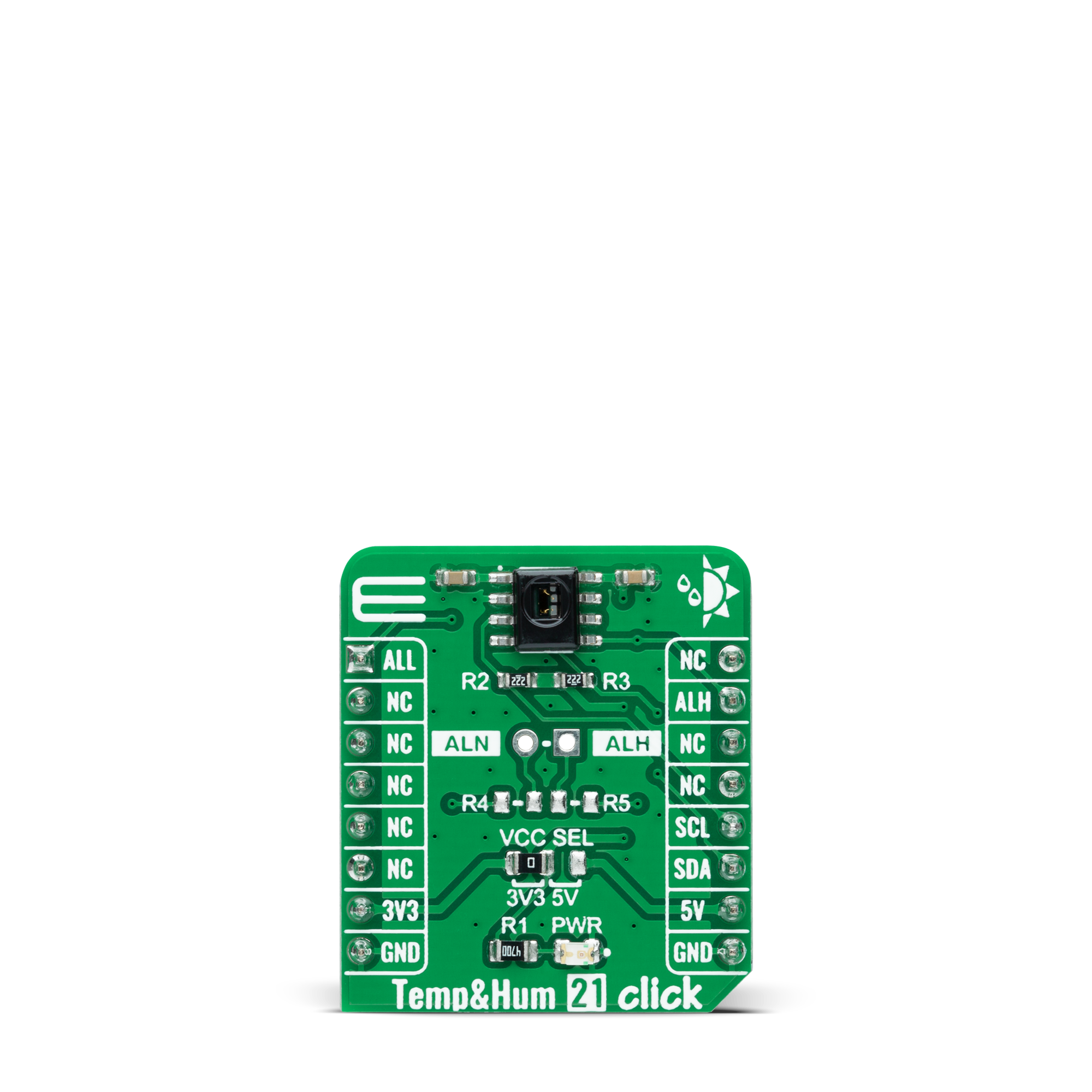
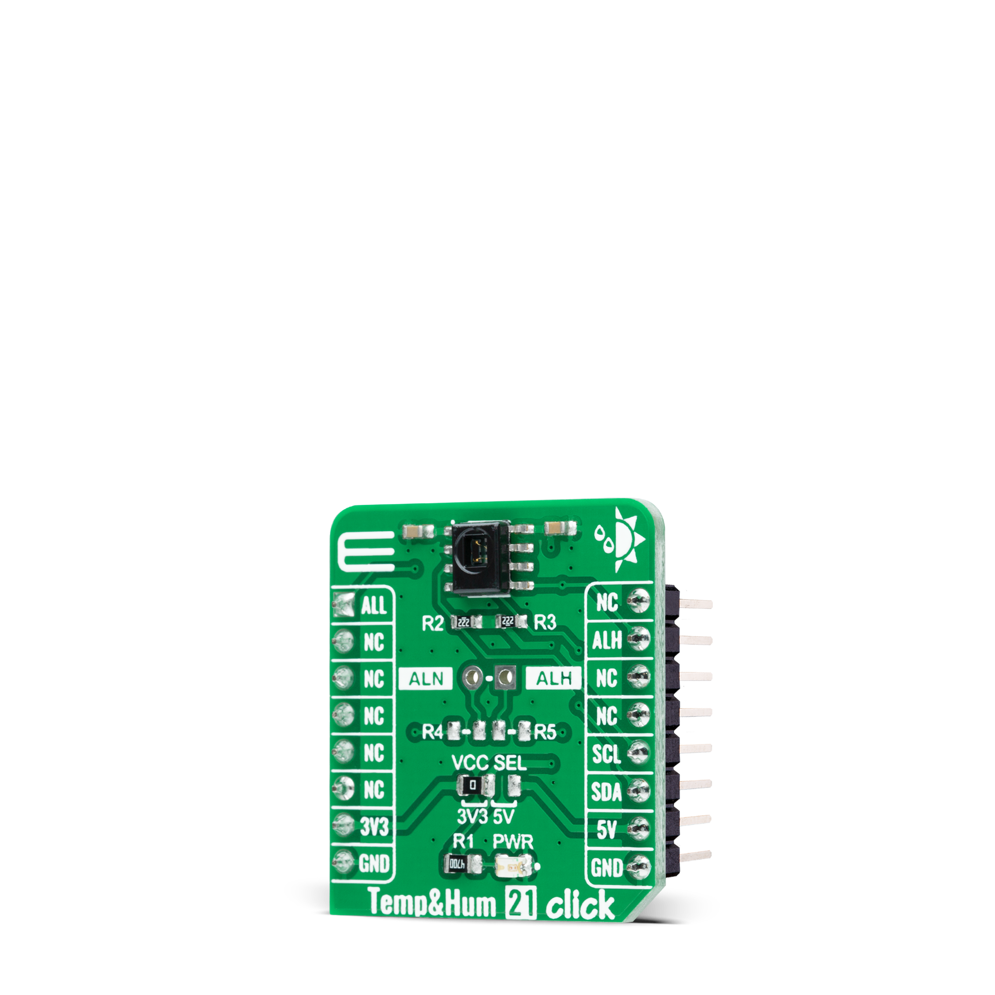
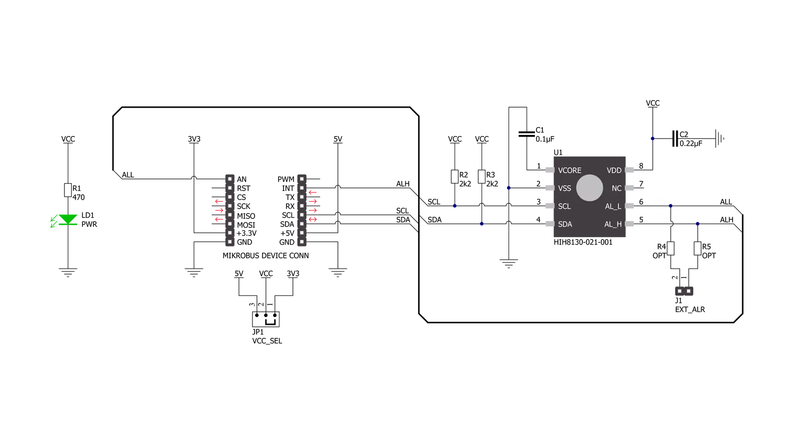
Temp&Hum 21 Click is based on the HIH8130-021-001, a highly accurate, fully-calibrated digital humidity and temperature sensor from Honeywell Sensing and Productivity Solutions. The humidity can be measured within a range of 0 to 100%RH, while the temperature sensor is designed for a range of -40 to +120°C. The typical accuracy for humidity is ±2%RH in the measuring range of 10 up to 90%RH at ambient temperature and ±0.5°C for its operating temperature range with low power consumption. The HIH8130-021-001 communicates with MCU using the standard I2C 2-Wire interface to read and write data supporting
Fast Mode operation with a clock frequency up to 400kHz, providing factory-calibrated 14-bit data to the host controller. High 14-bit humidity and 14-bit temperature sensor resolution within the application help the user’s design detect the slightest relative humidity or temperature change. It also has an alarm feature with configurable alarm thresholds routed to the ALH and ALL pins of the mikroBUS™ socket for preset control at a minimum and maximum humidity and temperature. These alarm thresholds are set to generate alarms when the actual values in the devices cross the defined threshold values.
To activate the external setting of the alarm thresholds, it is necessary to populate resistors R4 and R5, which are not populated by default, to enable an external setting on an unpopulated header in the middle of the Click board™. This Click board™ can operate with either 3.3V or 5V logic voltage levels selected via the VCC SEL jumper. This way, both 3.3V and 5V capable MCUs can use the communication lines properly. However, the Click board™ comes equipped with a library containing easy-to-use functions and an example code that can be used, as a reference, for further development.
Features overview
Development board
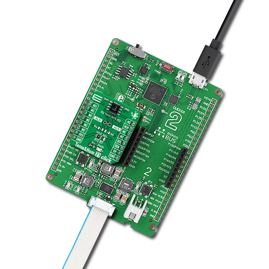
Clicker 2 for dsPIC33 is a compact starter development board that brings the flexibility of add-on Click boards™ to your favorite microcontroller, making it a perfect starter kit for implementing your ideas. It comes with an onboard 16-bit dsPIC33E family microcontroller, the dsPIC33EP512MU810 from Microchip, two mikroBUS™ sockets for Click board™ connectivity, a USB connector, LED indicators, buttons, a mikroProg programmer connector, and two 26-pin headers for interfacing with external electronics. Its compact design with clear and easily recognizable silkscreen markings allows you to build gadgets with unique
functionalities and features quickly. Each part of the Clicker 2 for dsPIC33 development kit contains the components necessary for the most efficient operation of the same board. In addition to the possibility of choosing the Clicker 2 for dsPIC33 programming method, using a USB HID mikroBootloader or an external mikroProg connector for dsPIC33 programmer, the Clicker 2 board also includes a clean and regulated power supply module for the development kit. It provides two ways of board-powering; through the USB Micro-B cable, where onboard voltage regulators provide the appropriate voltage levels to each
component on the board, or using a Li-Polymer battery via an onboard battery connector. All communication methods that mikroBUS™ itself supports are on this board, including the well-established mikroBUS™ socket, reset button, and several user-configurable buttons and LED indicators. Clicker 2 for dsPIC33 is an integral part of the Mikroe ecosystem, allowing you to create a new application in minutes. Natively supported by Mikroe software tools, it covers many aspects of prototyping thanks to a considerable number of different Click boards™ (over a thousand boards), the number of which is growing every day.

Microcontroller Overview
MCU Card / MCU
Architecture
dsPIC
MCU Memory (KB)
512
Silicon Vendor
Microchip
Pin count
100
RAM (Bytes)
53248
Used MCU Pins
mikroBUS™ mapper
Take a closer look
Click board™ Schematic
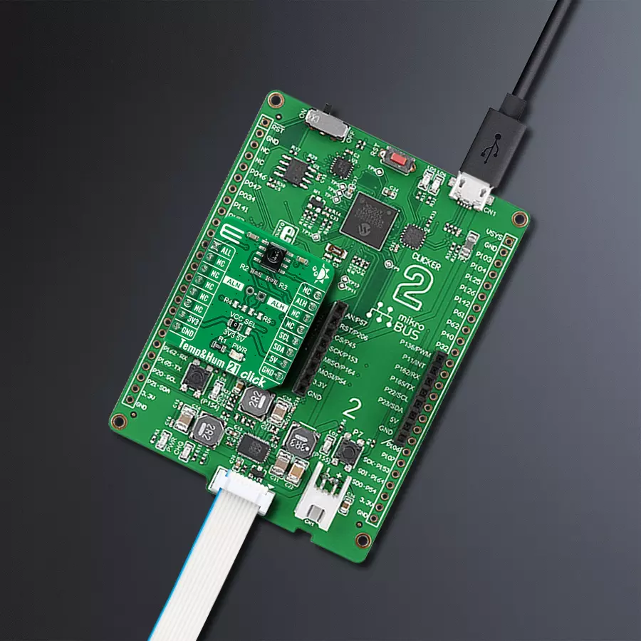
Step by step
Project assembly

Start by selecting your development board and Click board™. Begin with the Clicker 2 for dsPIC33 as your development board.


Software Support
Library Description
This library contains API for TempHum 21 Click driver.
Key functions:
temphum21_read_measurementThis function requests measurement and waits for a measurement to complete and, after that, reads the temperature in Celsius and relative humidity in percents.temphum21_get_all_pinThis function returns the alarm low (ALL) pin logic state.temphum21_get_alh_pinThis function returns the alarm high (ALH) pin logic state.
Open Source
Code example
The complete application code and a ready-to-use project are available through the NECTO Studio Package Manager for direct installation in the NECTO Studio. The application code can also be found on the MIKROE GitHub account.
/*!
 * @file main.c
 * @brief TempHum21 Click example
 *
 * # Description
 * This example demonstrates the use of Temp & Hum 21 Click board by reading
 * the temperature and humidity data.
 *
 * The demo application is composed of two sections :
 *
 * ## Application Init
 * Initializes the driver and performs the Click default configuration.
 *
 * ## Application Task
 * Reads the temperature (Celsius) and humidity (Percents) data and displays the
 * results on the USB UART approximately once per second. It also checks if any alarm
 * is detected on the humidity measurement.
 *
 * @author Stefan Filipovic
 *
 */

#include "board.h"
#include "log.h"
#include "temphum21.h"

static temphum21_t temphum21;
static log_t logger;

void application_init ( void )
{
    log_cfg_t log_cfg;  /**< Logger config object. */
    temphum21_cfg_t temphum21_cfg;  /**< Click config object. */

    /**
     * Logger initialization.
     * Default baud rate: 115200
     * Default log level: LOG_LEVEL_DEBUG
     * @note If USB_UART_RX and USB_UART_TX
     * are defined as HAL_PIN_NC, you will
     * need to define them manually for log to work.
     * See @b LOG_MAP_USB_UART macro definition for detailed explanation.
     */
    LOG_MAP_USB_UART( log_cfg );
    log_init( &logger, &log_cfg );
    log_info( &logger, " Application Init " );

    // Click initialization.
    temphum21_cfg_setup( &temphum21_cfg );
    TEMPHUM21_MAP_MIKROBUS( temphum21_cfg, MIKROBUS_1 );
    if ( I2C_MASTER_ERROR == temphum21_init( &temphum21, &temphum21_cfg ) )
    {
        log_error( &logger, " Communication init." );
        for ( ; ; );
    }

    if ( TEMPHUM21_ERROR == temphum21_default_cfg ( &temphum21 ) )
    {
        log_error( &logger, " Default configuration." );
        for ( ; ; );
    }

    log_info( &logger, " Application Task " );
}

void application_task ( void )
{
    float temperature = 0;
    float humidity = 0;
    if ( TEMPHUM21_STATUS_NORMAL_OP == temphum21_read_measurement ( &temphum21, &temperature, &humidity ) )
    {
        if ( temphum21_get_all_pin ( &temphum21 ) )
        {
            log_info ( &logger, " Alarm LOW detected " );
        }
        else if ( temphum21_get_alh_pin ( &temphum21 ) )
        {
            log_info ( &logger, " Alarm HIGH detected " );
        }

        log_printf ( &logger, " Temperature: %.2f C\r\n", temperature );
        log_printf ( &logger, " Humidity: %.2f %%\r\n\n", humidity );

        Delay_ms ( 1000 );
    }
}

int main ( void )
{
    /* Do not remove this line or clock might not be set correctly. */
    #ifdef PREINIT_SUPPORTED
    preinit();
    #endif

    application_init( );

    for ( ; ; )
    {
        application_task( );
    }

    return 0;
}

// ------------------------------------------------------------------------ END
Additional Support
Resources
Category:Temperature & humidity


