Create your thermo hygrometer using SHT45 and PIC32MZ1024EFH064
Monitor environmental conditions
Published Mar 01, 2023
Click board™
Temp&Hum 23 Click
Dev. board
PIC32MZ clicker
Compiler
NECTO Studio
MCU
PIC32MZ1024EFH064
Know the temperature and humidity of your environment
A
A
Hardware Overview
How does it work?
Temp&Hum 23 Click is based on the SHT45, a digital sensor platform for measuring relative humidity and temperature at different accuracy classes from Sensirion. The SHT45 builds on a wholly new and optimized CMOS chip offering reduced power consumption, high accuracy, and a digital I2C interface for the fastest data transfer. It covers extended operating humidity, and temperature ranges from 0 to 100%RH and from -40°C to 125°C with accuracies of ±1%RH and
±0.1°C. The SHT45 communicates with MCU using the standard I2C 2-wire interface. The sensor performs best when operated within the recommended average temperature and humidity range of 5-60°C and 20-80% RH. Long-term exposure to conditions outside the recommended normal range, especially at high relative humidity, may temporarily offset the RH signal. After returning to the recommended average temperature and humidity range, the sensor will recover to
within specifications. This Click board™ can only be operated with a 3.3V logic voltage level. The board must perform appropriate logic voltage level conversion before using MCUs with different logic levels. However, the Click board™ comes equipped with a library containing functions and an example code that can be used as a reference for further development.


Features overview
Development board
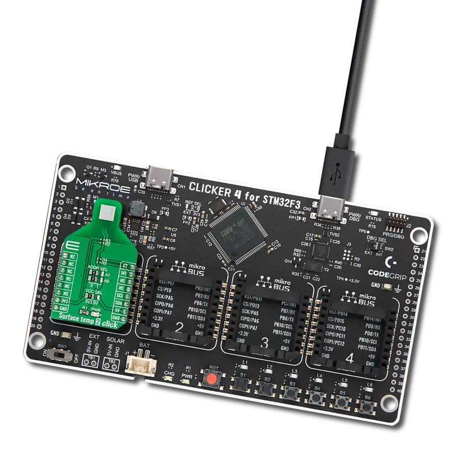
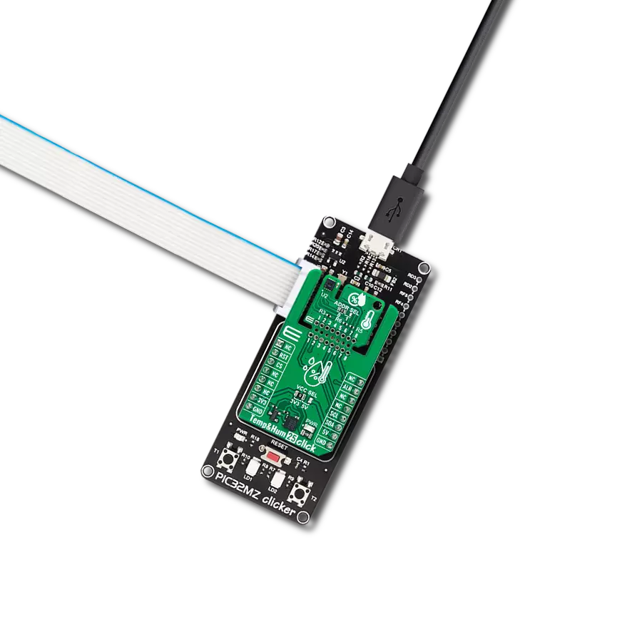
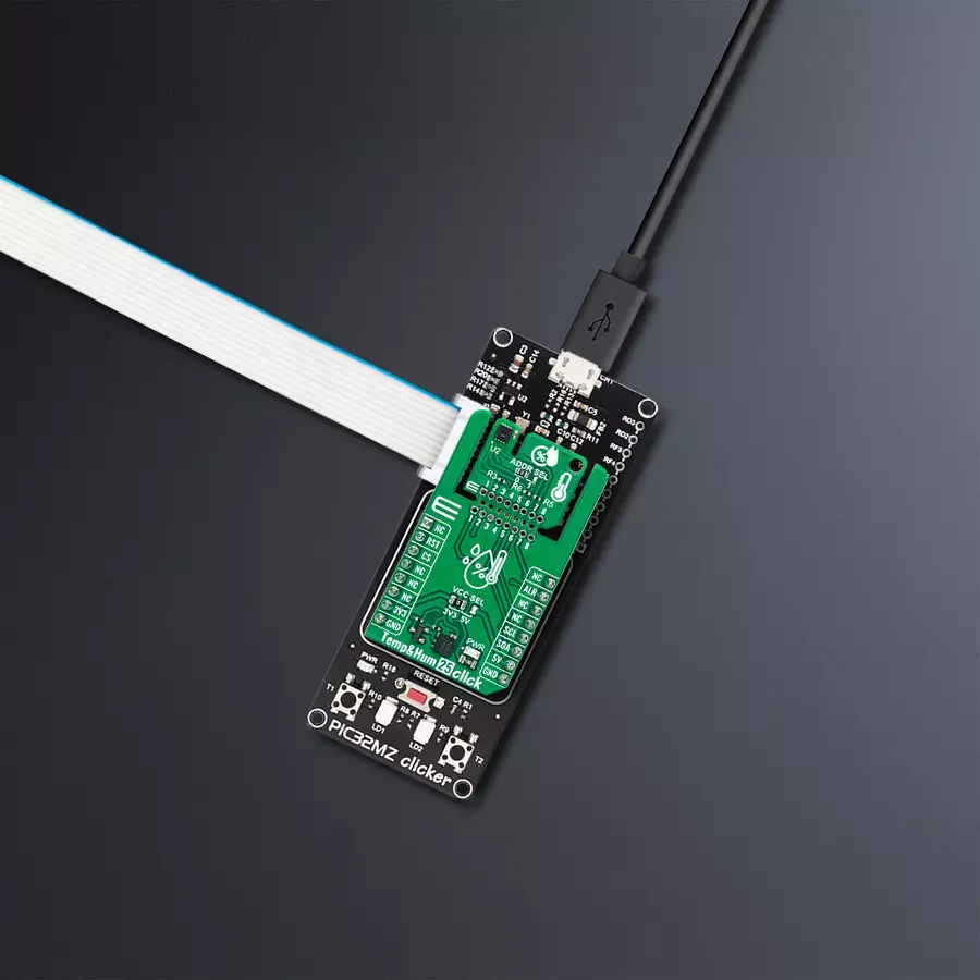
PIC32MZ Clicker is a compact starter development board that brings the flexibility of add-on Click boards™ to your favorite microcontroller, making it a perfect starter kit for implementing your ideas. It comes with an onboard 32-bit PIC32MZ microcontroller with FPU from Microchip, a USB connector, LED indicators, buttons, a mikroProg connector, and a header for interfacing with external electronics. Thanks to its compact design with clear and easy-recognizable silkscreen markings, it provides a fluid and immersive working experience, allowing access anywhere and under
any circumstances. Each part of the PIC32MZ Clicker development kit contains the components necessary for the most efficient operation of the same board. In addition to the possibility of choosing the PIC32MZ Clicker programming method, using USB HID mikroBootloader, or through an external mikroProg connector for PIC, dsPIC, or PIC32 programmer, the Clicker board also includes a clean and regulated power supply module for the development kit. The USB Micro-B connection can provide up to 500mA of current, which is more than enough to operate all onboard
and additional modules. All communication methods that mikroBUS™ itself supports are on this board, including the well-established mikroBUS™ socket, reset button, and several buttons and LED indicators. PIC32MZ Clicker is an integral part of the Mikroe ecosystem, allowing you to create a new application in minutes. Natively supported by Mikroe software tools, it covers many aspects of prototyping thanks to a considerable number of different Click boards™ (over a thousand boards), the number of which is growing every day.

Microcontroller Overview
MCU Card / MCU

Architecture
PIC32
MCU Memory (KB)
1024
Silicon Vendor
Microchip
Pin count
64
RAM (Bytes)
524288
Used MCU Pins
mikroBUS™ mapper
Take a closer look
Click board™ Schematic

Step by step
Project assembly

Start by selecting your development board and Click board™. Begin with the PIC32MZ clicker as your development board.


Track your results in real time
Application Output
1. Application Output - In Debug mode, the 'Application Output' window enables real-time data monitoring, offering direct insight into execution results. Ensure proper data display by configuring the environment correctly using the provided tutorial.

2. UART Terminal - Use the UART Terminal to monitor data transmission via a USB to UART converter, allowing direct communication between the Click board™ and your development system. Configure the baud rate and other serial settings according to your project's requirements to ensure proper functionality. For step-by-step setup instructions, refer to the provided tutorial.

3. Plot Output - The Plot feature offers a powerful way to visualize real-time sensor data, enabling trend analysis, debugging, and comparison of multiple data points. To set it up correctly, follow the provided tutorial, which includes a step-by-step example of using the Plot feature to display Click board™ readings. To use the Plot feature in your code, use the function: plot(*insert_graph_name*, variable_name);. This is a general format, and it is up to the user to replace 'insert_graph_name' with the actual graph name and 'variable_name' with the parameter to be displayed.

Software Support
Library Description
This library contains API for Temp&Hum 23 Click driver.
Key functions:
temphum23_soft_resetThis function performs the software reset by sending the soft reset command.temphum23_read_serial_numThis function reads the 4-bytes unique serial number by using I2C serial interface.temphum23_read_measurement_high_precisionThis function reads the temperature and humidity measurements with high precision.
Open Source
Code example
The complete application code and a ready-to-use project are available through the NECTO Studio Package Manager for direct installation in the NECTO Studio. The application code can also be found on the MIKROE GitHub account.
/*!
 * @file main.c
 * @brief TempHum 23 Click example
 *
 * # Description
 * This example demonstrates the use of Temp & Hum 23 Click board by reading
 * the temperature and humidity data.
 *
 * The demo application is composed of two sections :
 *
 * ## Application Init
 * Initializes the driver, performs the sensor software reset and then reads
 * and displays the sensor unique serial number.
 *
 * ## Application Task
 * Reads the temperature (degC) and the relative humidity (%RH) data and
 * displays the results on the USB UART approximately once per second.
 *
 * @author Stefan Filipovic
 *
 */

#include "board.h"
#include "log.h"
#include "temphum23.h"

static temphum23_t temphum23;
static log_t logger;

void application_init ( void )
{
    log_cfg_t log_cfg;  /**< Logger config object. */
    temphum23_cfg_t temphum23_cfg;  /**< Click config object. */

    /**
     * Logger initialization.
     * Default baud rate: 115200
     * Default log level: LOG_LEVEL_DEBUG
     * @note If USB_UART_RX and USB_UART_TX
     * are defined as HAL_PIN_NC, you will
     * need to define them manually for log to work.
     * See @b LOG_MAP_USB_UART macro definition for detailed explanation.
     */
    LOG_MAP_USB_UART( log_cfg );
    log_init( &logger, &log_cfg );
    log_info( &logger, " Application Init " );

    // Click initialization.
    temphum23_cfg_setup( &temphum23_cfg );
    TEMPHUM23_MAP_MIKROBUS( temphum23_cfg, MIKROBUS_1 );
    if ( I2C_MASTER_ERROR == temphum23_init( &temphum23, &temphum23_cfg ) )
    {
        log_error( &logger, " Communication init." );
        for ( ; ; );
    }

    if ( TEMPHUM23_OK == temphum23_soft_reset ( &temphum23 ) )
    {
        log_printf ( &logger, " Software reset\r\n" );
    }
    Delay_1sec ( );

    uint32_t serial_num;
    if ( TEMPHUM23_OK == temphum23_read_serial_num ( &temphum23, &serial_num ) )
    {
        log_printf ( &logger, " Serial number: 0x%.8LX\r\n", serial_num );
    }

    log_info( &logger, " Application Task " );
}

void application_task ( void )
{
    float temperature, humidity;
    if ( TEMPHUM23_OK == temphum23_read_measurement_high_precision ( &temphum23, &temperature, &humidity ) )
    {
        log_printf ( &logger, " Temperature: %.2f degC\r\n", temperature );
        log_printf ( &logger, " Humidity: %.2f %%RH\r\n\n", humidity );
        Delay_ms ( 1000 );
    }
}

int main ( void )
{
    /* Do not remove this line or clock might not be set correctly. */
    #ifdef PREINIT_SUPPORTED
    preinit();
    #endif

    application_init( );

    for ( ; ; )
    {
        application_task( );
    }

    return 0;
}

// ------------------------------------------------------------------------ END
Additional Support
Resources
Category:Temperature & humidity