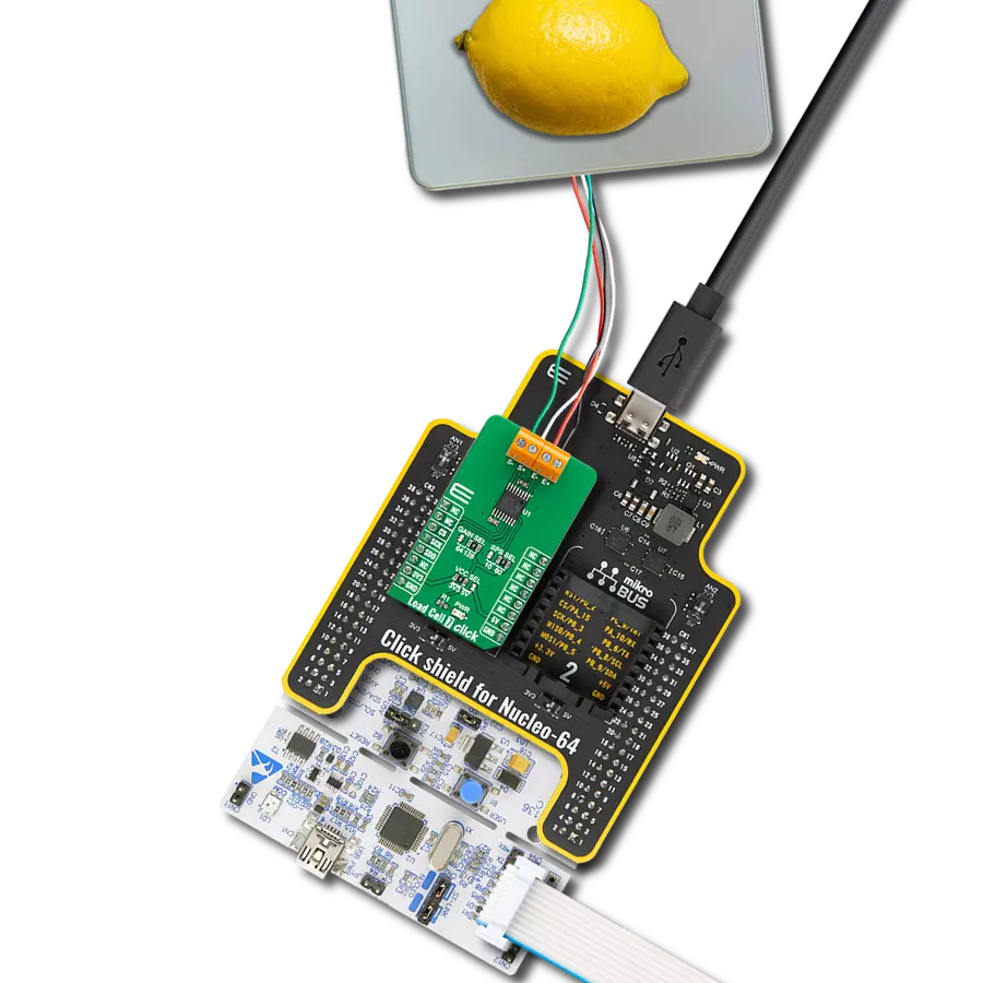
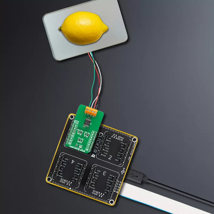
Measure force or weight of an object with ADS1230 and STM32F767BI
Force meter
Published Mar 04, 2023
Click board™
Load Cell 7 Click
Dev. board
Clicker 4 for STM32
Compiler
NECTO Studio
MCU
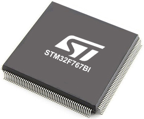
STM32F767BI
Complete front-end for bridge sensing applications
A
A
Hardware Overview
How does it work?
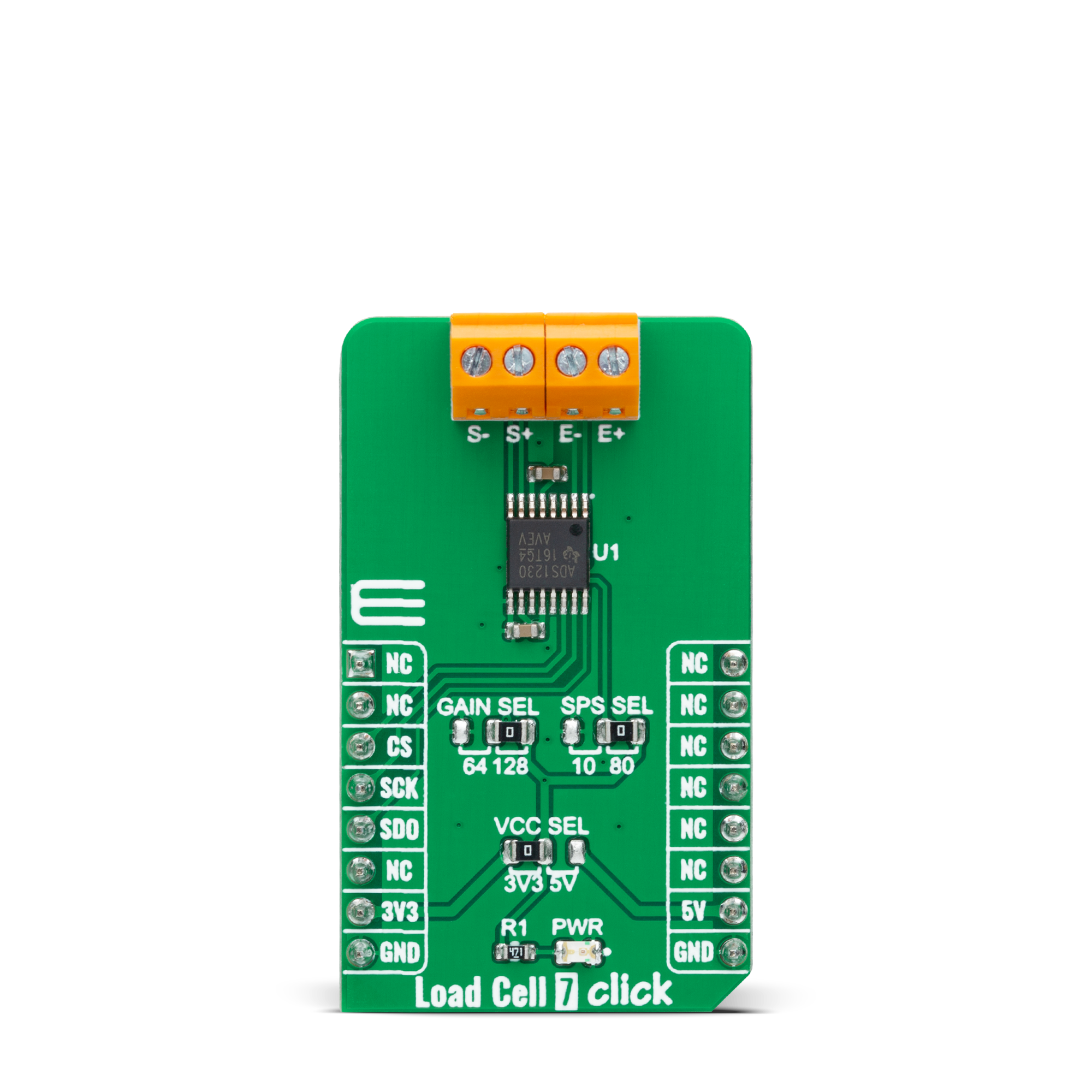
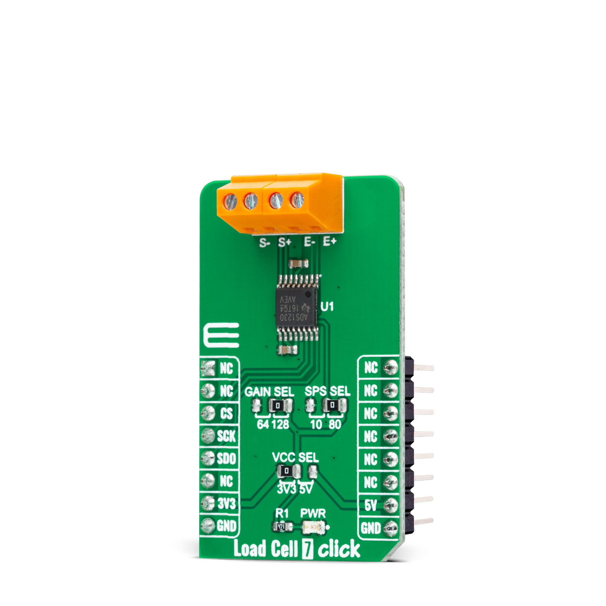
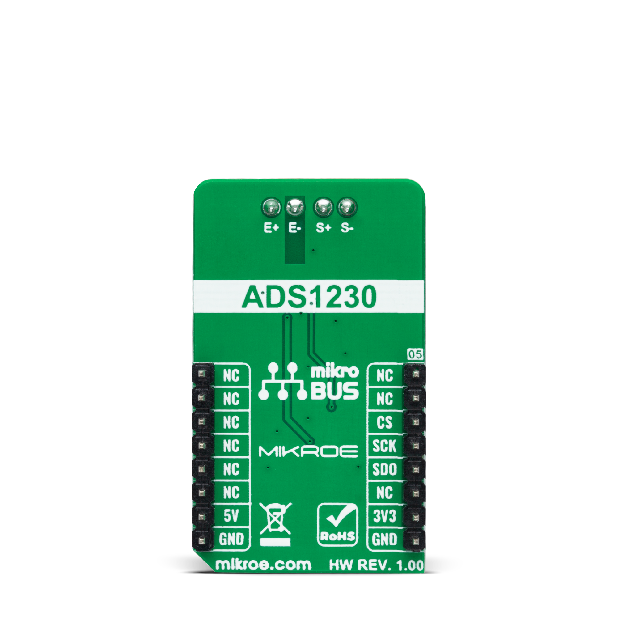
Load Cell 7 Click is based on the ADS1230, a high accuracy, low noise, and low power 20-bit ΣΔ ADC with an outstanding noise performance from Texas Instruments. It includes a low-noise PGA, internal oscillator, third-order delta-sigma (ΔΣ) modulator, and fourth-order digital filter, thus providing a complete front-end solution for bridge sensor applications. The ADS1230 is easy to configure, and all digital control is accomplished through dedicated pins; there are no programmable registers. The conversions from the ADS1230 are sent to the MCU through SPI serial interface, with the digital information converted to weight. The low-noise PGA has a selectable gain,
performed by an onboard SMD jumper labeled as GAIN SEL to an appropriate position marked as 64 and 128, supporting a full-scale differential input of ±39mV or ±19.5mV, respectively. Besides, data can be output at 10SPS for excellent 50Hz and 60Hz rejection or at 80SPS when higher speeds are needed. The onboard SMD jumper labeled SPS SEL can select this feature, placing it in an appropriate position marked as 10 and 80. The ADS1230 can be put in a low-power standby mode or shut off completely in power-down mode. This Click board™ uses the 4-wire load cell configuration, with two sense pins and two output connections. The load cell differential S lines connected to
the AD7780 reference inputs create a ratiometric configuration immune to low-frequency power supply excitation voltage changes. Those sense pins are connected to the high and low sides of the Wheatstone bridge, where voltage can be accurately measured, regardless of the voltage drop due to the wiring resistance. This Click board™ can operate with either 3.3V or 5V logic voltage levels selected via the VCC SEL jumper. This way, both 3.3V and 5V capable MCUs can use the communication lines properly. However, the Click board™ comes equipped with a library containing easy-to-use functions and an example code that can be used, as a reference, for further development.
Features overview
Development board
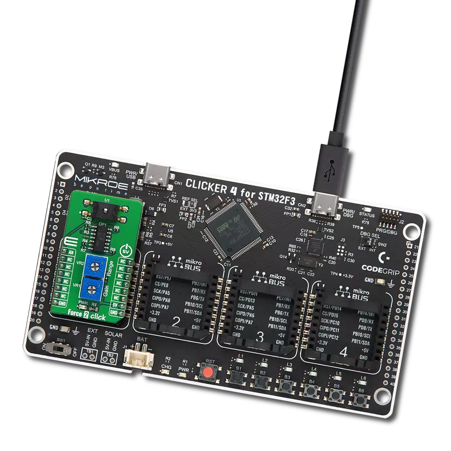
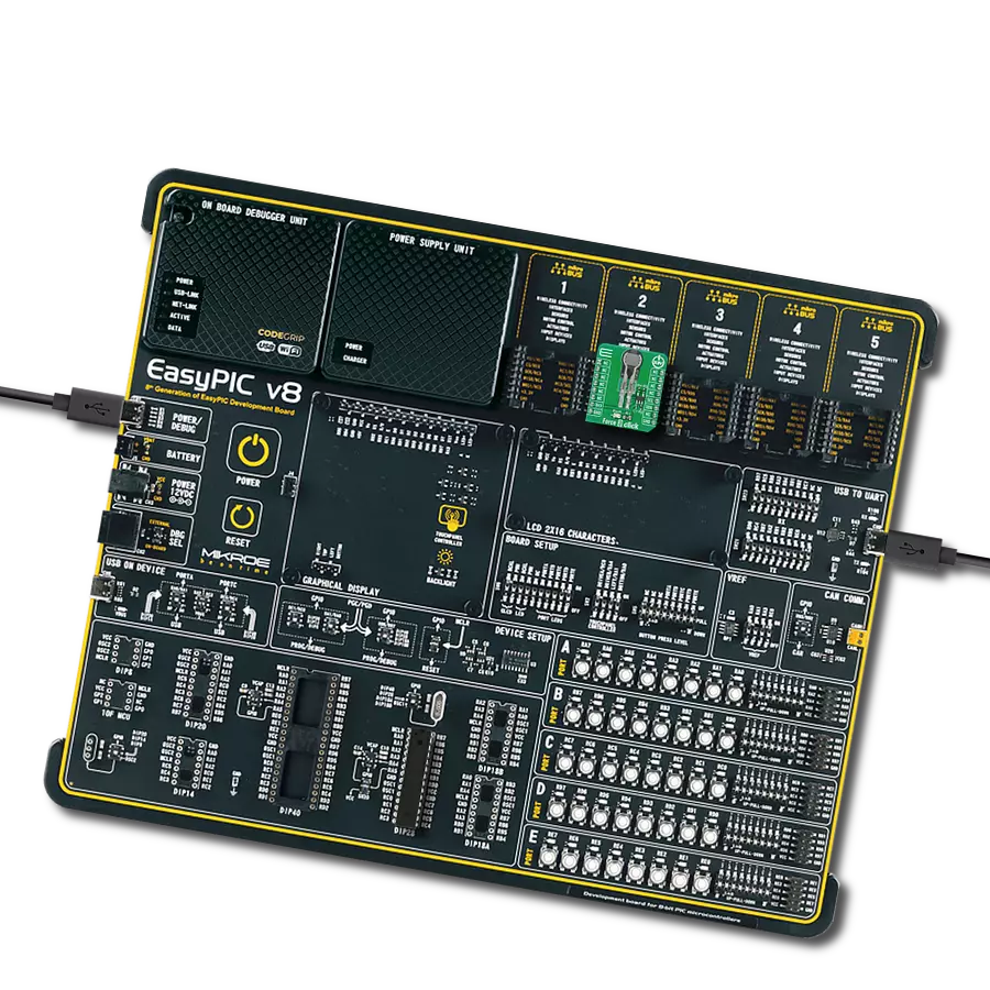
Clicker 4 for STM32 is a compact development board designed as a complete solution that brings the flexibility of add-on Click boards™ to your favorite microcontroller, making it a perfect starter kit for implementing your ideas. It comes with an onboard 32-bit ARM Cortex-M4 microcontroller, the STM32F767BI from STMicroelectronics, four mikroBUS™ sockets for Click board™ connectivity, a USB connector, LED indicators, buttons, a debugger/programmer connector, two 23-pin headers for interfacing with external electronics, and more. Thanks to innovative manufacturing technology, it allows you to build gadgets with
unique functionalities and features quickly. Each part of the Clicker 4 for STM32 development kit contains the components necessary for the most efficient operation of the same board. In addition to the possibility of choosing the Clicker 4 for STM32 programming method, using an external CODEGRIP or mikroProg programmer connected to the onboard JTAG/SWD header, the Clicker 4 board also includes a clean and regulated power supply block. It provides several ways of board-powering; through the USB Type-C (USB-C) connector using a power supply delivered by the USB HOST (i.e., personal computer), USB wall
adapter, or a Li-Po/Li-Ion battery via an onboard battery connector. All communication methods that mikroBUS™ itself supports are on this board (plus USB-DEVICE), including the well-established mikroBUS™ socket, several user-configurable buttons, and LED indicators. Clicker 4 for STM32 is an integral part of the Mikroe ecosystem, allowing you to create a new application in minutes. Natively supported by Mikroe software tools, it covers many aspects of prototyping thanks to a considerable number of different Click boards™ (over a thousand boards), the number of which is growing every day.

Microcontroller Overview
MCU Card / MCU
Architecture
ARM Cortex-M7
MCU Memory (KB)
2048
Silicon Vendor
STMicroelectronics
Pin count
208
RAM (Bytes)
524288
Used MCU Pins
mikroBUS™ mapper
Take a closer look
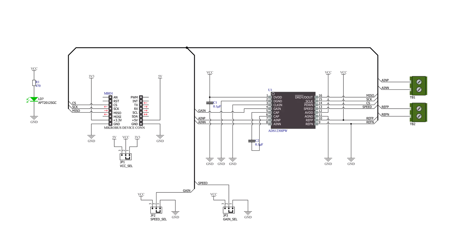
Click board™ Schematic
Step by step
Project assembly

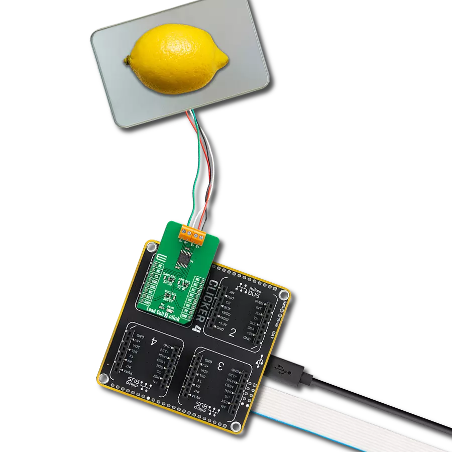
Start by selecting your development board and Click board™. Begin with the Clicker 4 for STM32 as your development board.


Software Support
Library Description
This library contains API for Load Cell 7 Click driver.
Key functions:
loadcell7_tare_scaleThis function calculates the @b ctx->tare_scale which is the raw ADC readings of the empty container.loadcell7_calibrate_weightThis function calibrates the weight by calculating the @b ctx->weight_scale for the input calibration weight.loadcell7_get_weightThis function calculates the weight of the goods in grams.
Open Source
Code example
The complete application code and a ready-to-use project are available through the NECTO Studio Package Manager for direct installation in the NECTO Studio. The application code can also be found on the MIKROE GitHub account.
/*!
 * @file main.c
 * @brief Load Cell 7 Click example
 *
 * # Description
 * This example demonstrates the use of Load Cell 7 Click by measuring the weight
 * in grams of the goods from the load cell sensor connected to the Click board.
 *
 * The demo application is composed of two sections :
 *
 * ## Application Init
 * Initializes the driver and reads the tare scale of the empty container, and after
 * that, it calibrates the weight scale with a known calibration weight.
 *
 * ## Application Task
 * Reads the net weight of the goods in grams approximately once per second and logs the
 * results on the USB UART.
 *
 * @author Stefan Filipovic
 *
 */

#include "board.h"
#include "log.h"
#include "loadcell7.h"

// Enter below the weight in grams of the goods with a known weight which
// you will use to calibrate the scale weight.
#define LOADCELL7_CALIBRATION_WEIGHT_G  1000.0

static loadcell7_t loadcell7;
static log_t logger;

void application_init ( void )
{
    log_cfg_t log_cfg;  /**< Logger config object. */
    loadcell7_cfg_t loadcell7_cfg;  /**< Click config object. */

    /**
     * Logger initialization.
     * Default baud rate: 115200
     * Default log level: LOG_LEVEL_DEBUG
     * @note If USB_UART_RX and USB_UART_TX
     * are defined as HAL_PIN_NC, you will
     * need to define them manually for log to work.
     * See @b LOG_MAP_USB_UART macro definition for detailed explanation.
     */
    LOG_MAP_USB_UART( log_cfg );
    log_init( &logger, &log_cfg );
    log_info( &logger, " Application Init " );

    // Click initialization.
    loadcell7_cfg_setup( &loadcell7_cfg );
    LOADCELL7_MAP_MIKROBUS( loadcell7_cfg, MIKROBUS_1 );
    if ( SPI_MASTER_ERROR == loadcell7_init( &loadcell7, &loadcell7_cfg ) )
    {
        log_error( &logger, " Communication init." );
        for ( ; ; );
    }

    log_printf( &logger, " Remove all goods from the scale in the following 5 sec.\r\n");
    Delay_ms ( 1000 );
    Delay_ms ( 1000 );
    Delay_ms ( 1000 );
    Delay_ms ( 1000 );
    Delay_ms ( 1000 );
    log_printf( &logger, " Calculating tare scale...\r\n");
    if ( LOADCELL7_OK == loadcell7_tare_scale ( &loadcell7 ) )
    {
        log_printf( &logger, " Tarring complete!\r\n\n");
    }
    else
    {
        log_error( &logger, " Calculating tare scale.");
        for ( ; ; );
    }

    log_printf( &logger, " Place a %ug calibration weight on the scale in the following 5 sec.\r\n",
                ( uint16_t ) LOADCELL7_CALIBRATION_WEIGHT_G );
    Delay_ms ( 1000 );
    Delay_ms ( 1000 );
    Delay_ms ( 1000 );
    Delay_ms ( 1000 );
    Delay_ms ( 1000 );
    log_printf( &logger, " Calibrating weight...\r\n");
    if ( LOADCELL7_OK == loadcell7_calibrate_weight ( &loadcell7, LOADCELL7_CALIBRATION_WEIGHT_G ) )
    {
        log_printf( &logger, " Calibration complete!\r\n\n");
    }
    else
    {
        log_error( &logger, " Calibrating weight.");
        for ( ; ; );
    }

    log_info( &logger, " Application Task " );
}

void application_task ( void )
{
    float weight;
    if ( LOADCELL7_OK == loadcell7_get_weight ( &loadcell7, &weight ) )
    {
        log_printf(&logger, " Weight : %.2f g\r\n", weight );
    }
}

int main ( void )
{
    /* Do not remove this line or clock might not be set correctly. */
    #ifdef PREINIT_SUPPORTED
    preinit();
    #endif

    application_init( );

    for ( ; ; )
    {
        application_task( );
    }

    return 0;
}

// ------------------------------------------------------------------------ END
Additional Support
Resources
Category:Force