Monitor vibration, shock, and achieve motion control with ADXL382 and PIC32MX470F512H
Low noise, low power, wide bandwidth, 3-axis MEMS accelerometer
Published Mar 04, 2025
Click board™
Accel 32 Click
Dev. board
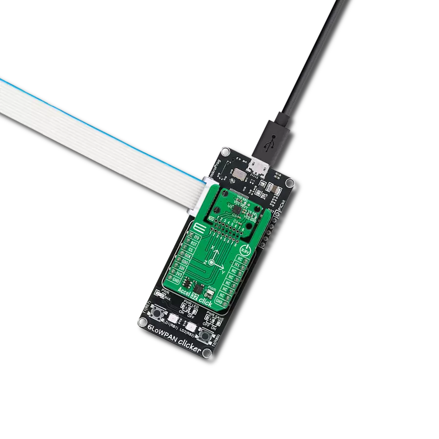
6LoWPAN clicker
Compiler
NECTO Studio
MCU
PIC32MX470F512H
Detect and monitor motion with high sensitivity perfect for structural monitoring, robotics, and wearables
A
A
Hardware Overview
How does it work?
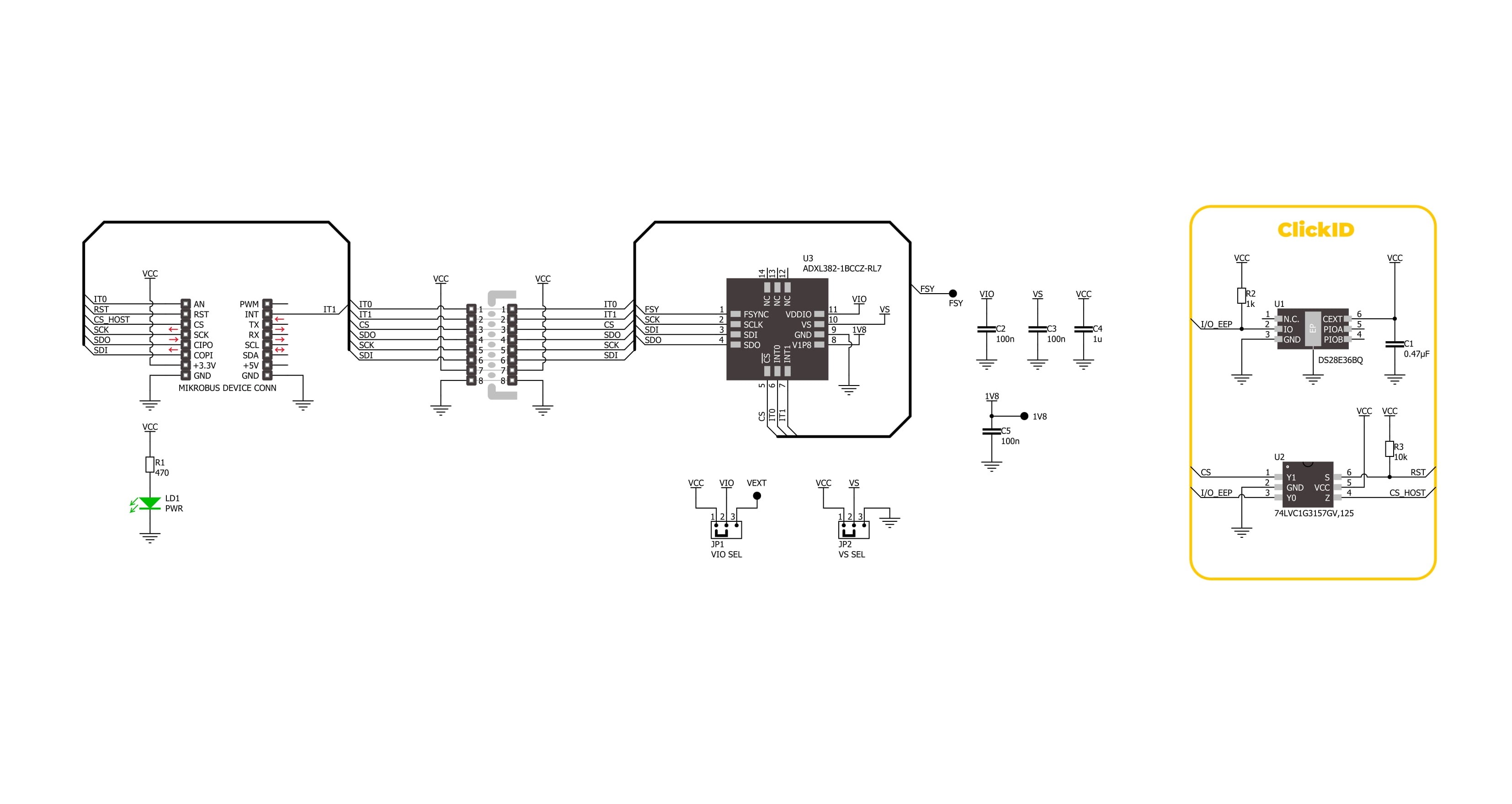
Accel 32 Click is based on the ADXL382-1, a low noise, low power, wide bandwidth, 3-axis MEMS accelerometer from Analog Devices designed for precise motion detection and monitoring applications. This advanced accelerometer offers exceptional measurement accuracy, supporting selectable ranges of ±15g, ±30g, and ±60g, ensuring flexibility across different use cases. The sensitivity varies accordingly, providing 2000LSB/g at ±15g and decreasing to 500LSB/g at ±60g, allowing users to tailor measurements to specific requirements. One of the key advantages of the ADXL382-1 is its industry-leading noise performance, making it an ideal solution for precision applications like condition-based monitoring, structural health monitoring, seismic imaging, robotics, audio and active noise cancellation (ANC), and more requiring minimal calibration effort. Thanks to its low noise density and power consumption, the ADXL382-1 excels in environments where precise motion capture is required, such as measuring audio signals or detecting heart sounds, even amidst strong vibrations. The version implemented on this board, ADXL382-1BCCZ-RL7, uses an SPI interface for fast and reliable data transfer and communication with the host MCU. Alongside its primary motion sensing capabilities, the ADXL382-1 integrates several advanced features that enhance its overall
functionality. These include an integrated micropower temperature sensor for environmental monitoring and built-in single, double, and triple tap detection mechanisms supported by a state machine designed to prevent false triggering. This Click board™ is designed in a unique format supporting the newly introduced MIKROE feature called "Click Snap." Unlike the standardized version of Click boards, this feature allows the main sensor area to become movable by breaking the PCB, opening up many new possibilities for implementation. Thanks to the Snap feature, the ADXL382-1 can operate autonomously by accessing its signals directly on the pins marked 1-8. Additionally, the Snap part includes a specified and fixed screw hole position, enabling users to secure the Snap board in their desired location. Accel 32 Click communicates with the host MCU via a 4-wire SPI interface, supporting a maximum clock frequency of 8MHz, ensuring efficient and reliable data transfer. In addition to the SPI interface, the board includes two configurable interrupt pins, IT0 and IT1, which act as an event-detection interrupt, essential for reliable motion-activated features. These include data-ready interrupts, generic interrupts like any or no-motion detection, free-fall detection, and tap detection. On the back side of the board, an additional signal from the ADXL382-1 is provided through the FSY
test point, which serves as an interrupt input in FIFO trigger mode. This signal is optional, allowing users to use it for additional functionalities. The Snap section of the board includes two jumpers, VIO SEL and VS SEL, which provide flexible power configuration options for the ADXL382-1. The VIO SEL jumper allows users to select the logic voltage for the ADXL382-1, offering a choice between a fixed 3.3V supply from the mikroBUS™ 3V3 power rail or an external power supply ranging from 1.14V to 3.6V. When using an external power source, the VIO SEL jumper must be set to the VEXT position, with the external voltage applied through the VEXT test point. The VS SEL jumper controls the power supply for the ADXL382-1's internal circuitry; when set to the VCC position, the ADXL382-1 uses its internal LDO regulators to generate a nominal 1.8V output, accessible via the 1V8 test point on the back of the board. Switching the VS SEL jumper to the GND position disables the internal LDO regulators, enabling users to supply the 1V8 pin externally, providing power for the internal analog and digital logic. This Click board™ can be operated only with a 3.3V logic voltage level. The board must perform appropriate logic voltage level conversion before using MCUs with different logic levels. It also comes equipped with a library containing functions and example code that can be used as a reference for further development.

Features overview
Development board
6LoWPAN Clicker is a compact starter development board that brings the flexibility of add-on Click boards™ to your favorite microcontroller, making it a perfect starter kit for implementing your ideas. It comes with an onboard 32-bit PIC microcontroller, the PIC32MX470F512H from Microchip, a USB connector, LED indicators, buttons, a mikroProg connector, and a header for interfacing with external electronics. Along with this microcontroller, the board also contains a 2.4GHz ISM band transceiver, allowing you to add wireless communication to your target application. Its compact design provides a fluid and immersive working experience, allowing access anywhere
and under any circumstances. Each part of the 6LoWPAN Clicker development kit contains the components necessary for the most efficient operation of the same board. In addition to the possibility of choosing the 6LoWPAN Clicker programming method, using USB HID mikroBootloader, or through an external mikroProg connector for PIC, dsPIC, or PIC32 programmer, the Clicker board also includes a clean and regulated power supply module for the development kit. The USB Micro-B connection can provide up to 500mA of current for the Clicker board, which is more than enough to operate all onboard and additional modules, or it can power
over two standard AA batteries. All communication methods that mikroBUS™ itself supports are on this board, including the well-established mikroBUS™ socket, reset button, and several buttons and LED indicators. 6LoWPAN Clicker is an integral part of the Mikroe ecosystem, allowing you to create a new application in minutes. Natively supported by Mikroe software tools, it covers many aspects of prototyping thanks to a considerable number of different Click boards™ (over a thousand boards), the number of which is growing every day.

Microcontroller Overview
MCU Card / MCU

Architecture
PIC32
MCU Memory (KB)
512
Silicon Vendor
Microchip
Pin count
64
RAM (Bytes)
131072
Used MCU Pins
mikroBUS™ mapper
Take a closer look
Click board™ Schematic
Step by step
Project assembly

Start by selecting your development board and Click board™. Begin with the 6LoWPAN clicker as your development board.


Track your results in real time
Application Output
1. Application Output - In Debug mode, the 'Application Output' window enables real-time data monitoring, offering direct insight into execution results. Ensure proper data display by configuring the environment correctly using the provided tutorial.

2. UART Terminal - Use the UART Terminal to monitor data transmission via a USB to UART converter, allowing direct communication between the Click board™ and your development system. Configure the baud rate and other serial settings according to your project's requirements to ensure proper functionality. For step-by-step setup instructions, refer to the provided tutorial.

3. Plot Output - The Plot feature offers a powerful way to visualize real-time sensor data, enabling trend analysis, debugging, and comparison of multiple data points. To set it up correctly, follow the provided tutorial, which includes a step-by-step example of using the Plot feature to display Click board™ readings. To use the Plot feature in your code, use the function: plot(*insert_graph_name*, variable_name);. This is a general format, and it is up to the user to replace 'insert_graph_name' with the actual graph name and 'variable_name' with the parameter to be displayed.

Software Support
Library Description
Accel 32 Click demo application is developed using the NECTO Studio, ensuring compatibility with mikroSDK's open-source libraries and tools. Designed for plug-and-play implementation and testing, the demo is fully compatible with all development, starter, and mikromedia boards featuring a mikroBUS™ socket.
Example Description
This example demonstrates the use of Accel 32 Click board by reading and displaying the accelerometer data (X, Y, and Z axis) and a temperature measurement in degrees Celsius.
Key functions:
accel32_cfg_setup- This function initializes Click configuration structure to initial values.accel32_init- This function initializes all necessary pins and peripherals used for this Click board.accel32_default_cfg- Click Default Configuration function.accel32_set_accel_fsr- This function sets the accel measurement full scale range.accel32_get_data- This function reads both accelerometer and temperature data from the device.
Application Init
Initializes the driver and performs the Click default configuration.
Application Task
Reads the accelerometer and temperature measurements. The results are displayed on the USB UART every 100 ms.
Open Source
Code example
The complete application code and a ready-to-use project are available through the NECTO Studio Package Manager for direct installation in the NECTO Studio. The application code can also be found on the MIKROE GitHub account.
/*!
 * @file main.c
 * @brief Accel 32 Click example
 *
 * # Description
 * This example demonstrates the use of Accel 32 Click board by reading and
 * displaying the accelerometer data (X, Y, and Z axis) and a temperature
 * measurement in degrees Celsius.
 *
 * The demo application is composed of two sections :
 *
 * ## Application Init
 * Initializes the driver and performs the Click default configuration.
 *
 * ## Application Task
 * Reads the accelerometer and temperature measurements.
 * The results are displayed on the USB UART every 100 ms.
 *
 * @author Stefan Filipovic
 *
 */

#include "board.h"
#include "log.h"
#include "accel32.h"

static accel32_t accel32;
static log_t logger;

void application_init ( void )
{
    log_cfg_t log_cfg;  /**< Logger config object. */
    accel32_cfg_t accel32_cfg;  /**< Click config object. */

    /**
     * Logger initialization.
     * Default baud rate: 115200
     * Default log level: LOG_LEVEL_DEBUG
     * @note If USB_UART_RX and USB_UART_TX
     * are defined as HAL_PIN_NC, you will
     * need to define them manually for log to work.
     * See @b LOG_MAP_USB_UART macro definition for detailed explanation.
     */
    LOG_MAP_USB_UART( log_cfg );
    log_init( &logger, &log_cfg );
    log_info( &logger, " Application Init " );

    // Click initialization.
    accel32_cfg_setup( &accel32_cfg );
    ACCEL32_MAP_MIKROBUS( accel32_cfg, MIKROBUS_1 );
    if ( SPI_MASTER_ERROR == accel32_init( &accel32, &accel32_cfg ) )
    {
        log_error( &logger, " Communication init." );
        for ( ; ; );
    }

    if ( ACCEL32_ERROR == accel32_default_cfg ( &accel32 ) )
    {
        log_error( &logger, " Default configuration." );
        for ( ; ; );
    }

    log_info( &logger, " Application Task " );
}

void application_task ( void )
{
    accel32_data_t meas_data;
    if ( ACCEL32_OK == accel32_get_data ( &accel32, &meas_data ) )
    {
        log_printf( &logger, " Accel X: %.3f g\r\n", meas_data.accel.x );
        log_printf( &logger, " Accel Y: %.3f g\r\n", meas_data.accel.y );
        log_printf( &logger, " Accel Z: %.3f g\r\n", meas_data.accel.z );
        log_printf( &logger, " Temperature: %.1f degC\r\n\n", meas_data.temperature );
        Delay_ms ( 100 );
    }
}

int main ( void )
{
    /* Do not remove this line or clock might not be set correctly. */
    #ifdef PREINIT_SUPPORTED
    preinit();
    #endif

    application_init( );

    for ( ; ; )
    {
        application_task( );
    }

    return 0;
}

// ------------------------------------------------------------------------ END
Additional Support
Resources
Category:Motion


