Control the speed, direction, and torque of a BLDC motor with ATmega8A and STM32F302VC
Three-phase brushless DC (BLDC) motor control solution
Published Jul 22, 2025
Click board™
Brushless 18 Click
Dev. board
CLICKER 4 for STM32F302VCT6
Compiler
NECTO Studio
MCU
STM32F302VC
Control high-speed, sensorless BLDC motors with precision, perfect for drones, cooling systems, and robotic applications
A
A
Hardware Overview
How does it work?
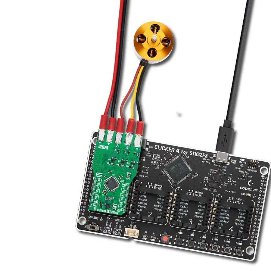
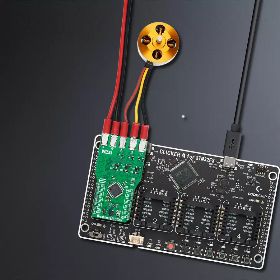
Brushless 18 Click is based on the ATmega8A, an 8-bit microcontroller from Microchip, offering a practical and efficient solution for controlling three-phase sensorless brushless motors (BLDC motors). These motors boast significant advantages over traditional DC motors. Their contactless design offers extended durability, superior torque, and high rotational speed, making them an excellent choice for lightweight, high-performance applications. These applications include propulsion systems for drones, where high speed, lightweight construction, and energy efficiency are critical; electronic cooling devices such as computer fans and industrial cooling systems that demand quiet and reliable operation; small household appliances like vacuum cleaners and air purifiers, and robotic mechanisms where their high torque and control accuracy are essential for smooth and precise movements. This Click board™ ensures precise control over BLDC motor operation and processes driving commands received via the PWM signal from the mikroBUS™
socket, enabling smooth and reliable motor control. Since the ATmega8A's output cannot directly drive the motor coils, it functions as the controller for a power circuit. This circuit consists of six high-performance N-channel MOSFETs, the STL120N4F6AG from STMicroelectronics, capable of efficiently switching power from an external source to the motor's stator coils. These MOSFETs can handle currents up to 50A, allowing the board to support demanding motor applications. The external power source can range from 0 to 40V, providing versatility in various use cases. The motor is connected via dedicated onboard terminals A, B, and C, ensuring secure and straightforward connections. This design, paired with robust components, allows Brushless 18 Click to deliver reliable performance and make it a go-to solution for high-speed motor-driven applications. A unique feature of this Click board™ is the inclusion of bootloader pins, which are unpopulated by default and designed for the onboard ATmega8A
microcontroller. These pins provide direct access to the microcontroller's bootloader functionality, enabling easy firmware updates and reprogramming without needing an external programmer. This feature simplifies development and testing processes, allowing users to quickly load and debug custom firmware directly on the Click board™, making it an efficient and developer-friendly solution for various applications. This Click board™ uses both power rails, 3.3V and 5V, with the 3.3V rail dedicated exclusively to the ClickID functionality, while the 5V rail powers all other components, including the onboard ATmega8A microcontroller. Due to this design, the board requires appropriate logic voltage level conversion when interfacing with external MCUs operating at different logic levels. Also, it comes equipped with a library containing functions and an example code that can be used as a reference for further development.

Features overview
Development board
Clicker 4 for STM32F3 is a compact development board designed as a complete solution, you can use it to quickly build your own gadgets with unique functionalities. Featuring a STM32F302VCT6, four mikroBUS™ sockets for Click boards™ connectivity, power managment, and more, it represents a perfect solution for the rapid development of many different types of applications. At its core, there is a STM32F302VCT6 MCU, a powerful microcontroller by STMicroelectronics, based on the high-
performance Arm® Cortex®-M4 32-bit processor core operating at up to 168 MHz frequency. It provides sufficient processing power for the most demanding tasks, allowing Clicker 4 to adapt to any specific application requirements. Besides two 1x20 pin headers, four improved mikroBUS™ sockets represent the most distinctive connectivity feature, allowing access to a huge base of Click boards™, growing on a daily basis. Each section of Clicker 4 is clearly marked, offering an intuitive and clean interface. This makes working with the development
board much simpler and thus, faster. The usability of Clicker 4 doesn’t end with its ability to accelerate the prototyping and application development stages: it is designed as a complete solution which can be implemented directly into any project, with no additional hardware modifications required. Four mounting holes [4.2mm/0.165”] at all four corners allow simple installation by using mounting screws. For most applications, a nice stylish casing is all that is needed to turn the Clicker 4 development board into a fully functional, custom design.

Microcontroller Overview
MCU Card / MCU

Architecture
ARM Cortex-M4
MCU Memory (KB)
256
Silicon Vendor
STMicroelectronics
Pin count
100
RAM (Bytes)
40960
Used MCU Pins
mikroBUS™ mapper
Take a closer look
Click board™ Schematic

Step by step
Project assembly

Start by selecting your development board and Click board™. Begin with the CLICKER 4 for STM32F302VCT6 as your development board.


Track your results in real time
Application Output
1. Application Output - In Debug mode, the 'Application Output' window enables real-time data monitoring, offering direct insight into execution results. Ensure proper data display by configuring the environment correctly using the provided tutorial.

2. UART Terminal - Use the UART Terminal to monitor data transmission via a USB to UART converter, allowing direct communication between the Click board™ and your development system. Configure the baud rate and other serial settings according to your project's requirements to ensure proper functionality. For step-by-step setup instructions, refer to the provided tutorial.

3. Plot Output - The Plot feature offers a powerful way to visualize real-time sensor data, enabling trend analysis, debugging, and comparison of multiple data points. To set it up correctly, follow the provided tutorial, which includes a step-by-step example of using the Plot feature to display Click board™ readings. To use the Plot feature in your code, use the function: plot(*insert_graph_name*, variable_name);. This is a general format, and it is up to the user to replace 'insert_graph_name' with the actual graph name and 'variable_name' with the parameter to be displayed.

Software Support
Library Description
This library contains API for Brushless 18 Click driver.
Key functions:
brushless18_throttle_calib- This function performs the ESC throttle calibration.brushless18_drive_motor- This function drives the motor at the selected speed and direction.
Open Source
Code example
The complete application code and a ready-to-use project are available through the NECTO Studio Package Manager for direct installation in the NECTO Studio. The application code can also be found on the MIKROE GitHub account.
/*!
 * @file main.c
 * @brief Brushless 18 Click example
 *
 * # Description
 * This example demonstrates the use of the Brushless 18 Click board by driving the
 * motor in both directions at different speeds.
 *
 * The demo application is composed of two sections :
 *
 * ## Application Init
 * Initializes the driver and calibrates the Click board.
 *
 * ## Application Task
 * Changes the motor speed every 500 milliseconds with steps of 5%.
 * At the minimal speed, the motor switches direction. Each step will be logged
 * on the USB UART where you can track the program flow.
 *
 * @note
 * The theoretical maximal PWM Clock frequency for this Click board is 500 Hz.
 * The default PWM Clock frequency is set to 400 Hz. To achieve such a low frequency,
 * the user will probably need to decrease the MCU's main clock frequency in
 * the Setup MCU Settings.
 *
 * @author Stefan Filipovic
 *
 */

#include "board.h"
#include "log.h"
#include "brushless18.h"

static brushless18_t brushless18;
static log_t logger;

void application_init ( void )
{
    log_cfg_t log_cfg;  /**< Logger config object. */
    brushless18_cfg_t brushless18_cfg;  /**< Click config object. */

    /**
     * Logger initialization.
     * Default baud rate: 115200
     * Default log level: LOG_LEVEL_DEBUG
     * @note If USB_UART_RX and USB_UART_TX
     * are defined as HAL_PIN_NC, you will
     * need to define them manually for log to work.
     * See @b LOG_MAP_USB_UART macro definition for detailed explanation.
     */
    LOG_MAP_USB_UART( log_cfg );
    log_init( &logger, &log_cfg );
    log_info( &logger, " Application Init " );

    // Click initialization.
    brushless18_cfg_setup( &brushless18_cfg );
    BRUSHLESS18_MAP_MIKROBUS( brushless18_cfg, MIKROBUS_1 );
    if ( PWM_ERROR == brushless18_init( &brushless18, &brushless18_cfg ) )
    {
        log_error( &logger, " Communication init." );
        for ( ; ; );
    }

    if ( BRUSHLESS18_ERROR == brushless18_throttle_calib ( &brushless18 ) )
    {
        log_error( &logger, " Throttle calibration." );
        for ( ; ; );
    }

    log_info( &logger, " Application Task " );
}

void application_task ( void )
{
    static uint8_t direction = BRUSHLESS18_DIRECTION_CW;
    static int8_t speed = BRUSHLESS18_SPEED_MIN;
    static int8_t speed_step = 5;
    brushless18_drive_motor ( &brushless18, direction, speed );
    log_printf( &logger, " Direction: %s\r\n",
                ( char * ) ( BRUSHLESS18_DIRECTION_CW == direction ? "CW" : "CCW" ) );
    log_printf( &logger, " Speed: %u%%\r\n\n", ( uint16_t ) speed );
    Delay_ms ( 500 );

    speed += speed_step;
    if ( speed > BRUSHLESS18_SPEED_MAX )
    {
        speed_step = -speed_step;
        speed += speed_step;
        speed += speed_step;
    }
    else if ( speed < BRUSHLESS18_SPEED_MIN )
    {
        speed_step = -speed_step;
        speed += speed_step;
        direction ^= 1;
        Delay_ms ( 1000 );
    }
}

int main ( void )
{
    /* Do not remove this line or clock might not be set correctly. */
    #ifdef PREINIT_SUPPORTED
    preinit();
    #endif

    application_init( );

    for ( ; ; )
    {
        application_task( );
    }

    return 0;
}

// ------------------------------------------------------------------------ END
Additional Support
Resources
Category:Brushless


