Detect gestures, activity levels, and orientation with BNO085 and ATmega324P
9-axis IMU System in Package (SiP) solution for high-precision motion tracking and contextual sensing

Published Dec 23, 2024
Click board™
Smart DOF 4 Click
Dev. board
EasyAVR v7
Compiler
NECTO Studio
MCU
ATmega324P
Track motion with precision and advanced contextual sensing using a 9-axis IMU perfect for AR/VR and robotics
A
A
Hardware Overview
How does it work?
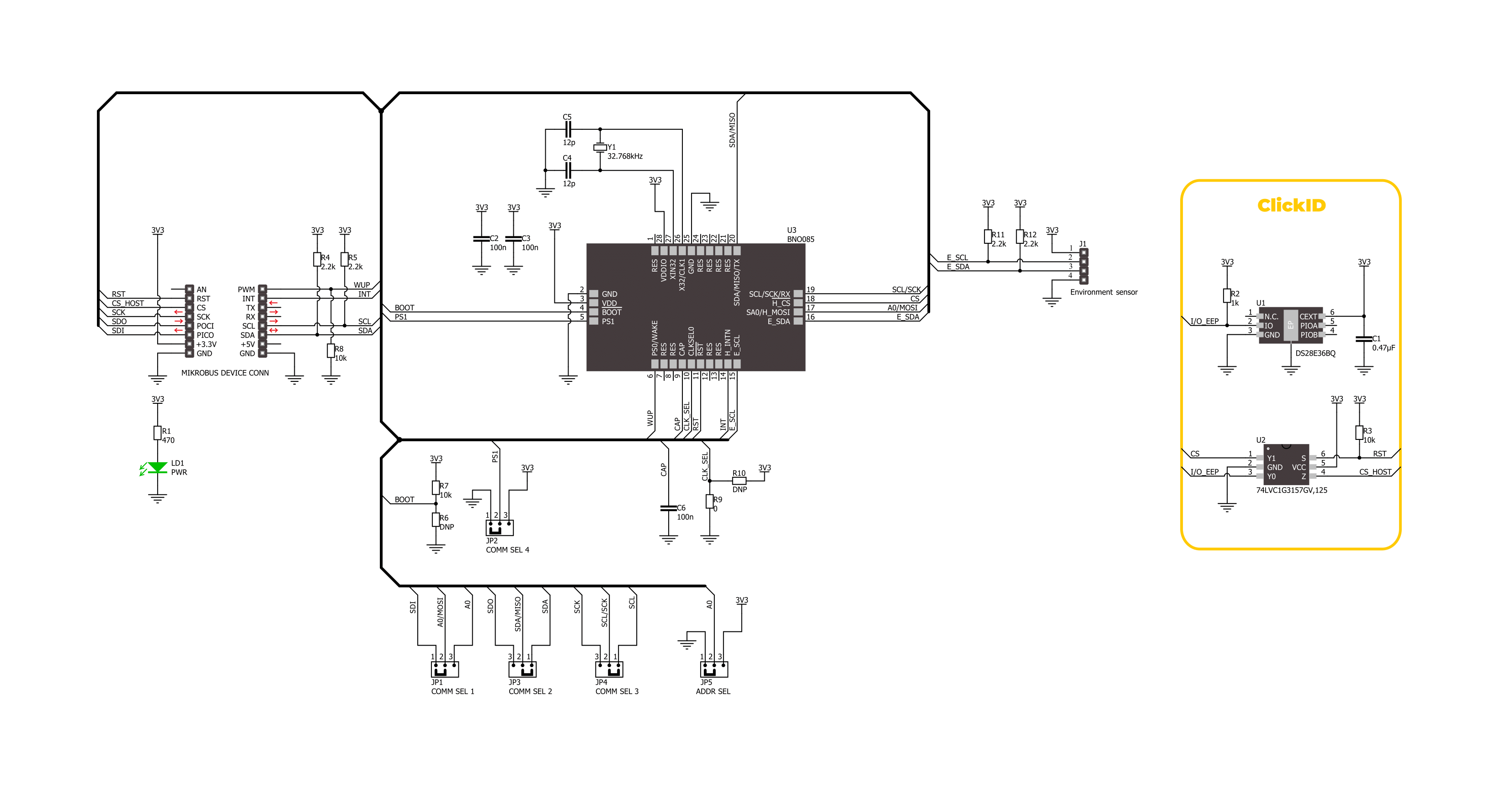
Smart DOF 4 Click is based on the BNO085, a 9-axis IMU System in Package (SiP) from CEVA, designed to deliver high-precision motion tracking and contextual sensing for advanced applications. The BNO085 integrates a triaxial 12-bit accelerometer with a range of ±8g, a triaxial 16-bit gyroscope with a range of ±2000 degrees per second, a triaxial geomagnetic sensor, and a 32-bit ARM® Cortex™-M0+ microcontroller running CEVA's SH-2 firmware. This IMU chip provides real-time, calibrated 3D orientation, heading, linear acceleration, and angular velocity, making it ideal for various motion-based solutions in consumer electronics (AR/VR head trackers), robotics, IoT devices, and beyond. The BNO085 excels in its ability to dynamically calibrate sensor data, compensating for environmental factors like temperature changes and sensor aging. It also supports various 3D orientation outputs, including rotation vectors, linear acceleration, and gravity, ensuring precise performance across diverse
scenarios. The core of this SiP is the SH-2 software, featuring CEVA's MotionEngine™ technology. MotionEngine transforms raw motion data from MEMS sensors into accurate, actionable motion outputs, supporting applications like gesture detection, activity monitoring, and dynamic motion control. With 'Always-On' capabilities, it provides features such as step counting, stability detection, tap detection, and gesture recognition. The SH-2 firmware is Android-compatible, supporting sensor types defined in Android 4.4 KitKat. Sensor data are accessed through the I2C or SPI interface, with a maximum frequency of 400kHz for I2C and 3MHz for SPI communication. The selection is made by positioning SMD jumpers labeled COMM SEL appropriately. Note that all the jumpers' positions must be on the same side, or the Click board™ may become unresponsive. While the I2C interface is selected, the BNO085 allows the least significant bit (LSB) of its I2C address to be chosen using the SMD jumper labeled ADDR SEL. This board also
uses additional pins from the mikroBUS™ socket to enhance functionality. The WUP pin wakes the processor from sleep mode during SPI communication, ensuring efficient power management. The RST pin provides a reset function for the sensor, activated by a LOW logic level, while the INT pin acts as an interrupt line, signaling various events detected during operation. Additionally, the BNO085 supports the integration of environmental sensors, such as pressure or ambient light sensors, via a secondary I2C interface accessible through an unsoldered header at the top of the board. This Click board™ can be operated only with a 3.3V logic voltage level. The board must perform appropriate logic voltage level conversion before using MCUs with different logic levels. It also comes equipped with a library containing functions and example code that can be used as a reference for further development.

Features overview
Development board
EasyAVR v7 is the seventh generation of AVR development boards specially designed for the needs of rapid development of embedded applications. It supports a wide range of 16-bit AVR microcontrollers from Microchip and has a broad set of unique functions, such as a powerful onboard mikroProg programmer and In-Circuit debugger over USB. The development board is well organized and designed so that the end-user has all the necessary elements in one place, such as switches, buttons, indicators, connectors, and others. With four different connectors for each port, EasyAVR v7 allows you to connect accessory boards, sensors, and custom electronics more
efficiently than ever. Each part of the EasyAVR v7 development board contains the components necessary for the most efficient operation of the same board. An integrated mikroProg, a fast USB 2.0 programmer with mikroICD hardware In-Circuit Debugger, offers many valuable programming/debugging options and seamless integration with the Mikroe software environment. Besides it also includes a clean and regulated power supply block for the development board. It can use a wide range of external power sources, including an external 12V power supply, 7-12V AC or 9-15V DC via DC connector/screw terminals, and a power source via the USB Type-B (USB-B)
connector. Communication options such as USB-UART and RS-232 are also included, alongside the well-established mikroBUS™ standard, three display options (7-segment, graphical, and character-based LCD), and several different DIP sockets which cover a wide range of 16-bit AVR MCUs. EasyAVR v7 is an integral part of the Mikroe ecosystem for rapid development. Natively supported by Mikroe software tools, it covers many aspects of prototyping and development thanks to a considerable number of different Click boards™ (over a thousand boards), the number of which is growing every day.

Microcontroller Overview
MCU Card / MCU

Architecture
AVR
MCU Memory (KB)
32
Silicon Vendor
Microchip
Pin count
40
RAM (Bytes)
2048
Used MCU Pins
mikroBUS™ mapper
Take a closer look
Click board™ Schematic
Step by step
Project assembly

Start by selecting your development board and Click board™. Begin with the EasyAVR v7 as your development board.


Track your results in real time
Application Output
1. Application Output - In Debug mode, the 'Application Output' window enables real-time data monitoring, offering direct insight into execution results. Ensure proper data display by configuring the environment correctly using the provided tutorial.

2. UART Terminal - Use the UART Terminal to monitor data transmission via a USB to UART converter, allowing direct communication between the Click board™ and your development system. Configure the baud rate and other serial settings according to your project's requirements to ensure proper functionality. For step-by-step setup instructions, refer to the provided tutorial.

3. Plot Output - The Plot feature offers a powerful way to visualize real-time sensor data, enabling trend analysis, debugging, and comparison of multiple data points. To set it up correctly, follow the provided tutorial, which includes a step-by-step example of using the Plot feature to display Click board™ readings. To use the Plot feature in your code, use the function: plot(*insert_graph_name*, variable_name);. This is a general format, and it is up to the user to replace 'insert_graph_name' with the actual graph name and 'variable_name' with the parameter to be displayed.

Software Support
Library Description
This library contains API for Smart DOF 4 Click driver.
Key functions:
smartdof4_read_pid- This function reads the product ID information.smartdof4_feature_set- This function sets a full feature report.smartdof4_read_data- This function reads the accelerometer (g), gyroscope (dps), and magnetometer (uT) 3-axis data from input report.
Open Source
Code example
The complete application code and a ready-to-use project are available through the NECTO Studio Package Manager for direct installation in the NECTO Studio. The application code can also be found on the MIKROE GitHub account.
/*!
 * @file main.c
 * @brief Smart DOF 4 Click example
 *
 * # Description
 * This example demonstrates the use of Smart DOF 4 Click board by reading
 * the accelerometer, gyroscope, and magnetometer data measurements.
 *
 * The demo application is composed of two sections :
 *
 * ## Application Init
 * Initializes the driver and performs the Click default configuration enabling
 * accelerometer, gyroscope, and magnetometer sensors with an output data rate of 10Hz.
 * After that, it reads the software version, part number, and build number information.
 *
 * ## Application Task
 * Reads the accelerometer (g), gyroscope (dps), and magnetometer (uT) measurements
 * and displays results on the USB UART every 100ms approximately.
 *
 * @author Stefan Filipovic
 *
 */

#include "board.h"
#include "log.h"
#include "smartdof4.h"

static smartdof4_t smartdof4;
static log_t logger;

void application_init ( void )
{
    log_cfg_t log_cfg;  /**< Logger config object. */
    smartdof4_cfg_t smartdof4_cfg;  /**< Click config object. */

    /**
     * Logger initialization.
     * Default baud rate: 115200
     * Default log level: LOG_LEVEL_DEBUG
     * @note If USB_UART_RX and USB_UART_TX
     * are defined as HAL_PIN_NC, you will
     * need to define them manually for log to work.
     * See @b LOG_MAP_USB_UART macro definition for detailed explanation.
     */
    LOG_MAP_USB_UART( log_cfg );
    log_init( &logger, &log_cfg );
    log_info( &logger, " Application Init " );

    // Click initialization.
    smartdof4_cfg_setup( &smartdof4_cfg );
    SMARTDOF4_MAP_MIKROBUS( smartdof4_cfg, MIKROBUS_1 );
    err_t init_flag = smartdof4_init( &smartdof4, &smartdof4_cfg );
    if ( ( I2C_MASTER_ERROR == init_flag ) || ( SPI_MASTER_ERROR == init_flag ) )
    {
        log_error( &logger, " Communication init." );
        for ( ; ; );
    }

    if ( SMARTDOF4_ERROR == smartdof4_default_cfg ( &smartdof4 ) )
    {
        log_error( &logger, " Default configuration." );
        for ( ; ; );
    }

    smartdof4_pid_t pid;
    if ( SMARTDOF4_OK == smartdof4_read_pid ( &smartdof4, &pid ) )
    {
        log_printf ( &logger, " SW Version: %u.%u.%u\r\n", ( uint16_t ) pid.sw_ver_major,
                                                           ( uint16_t ) pid.sw_ver_minor,
                                                           ( uint16_t ) pid.sw_ver_patch );
        log_printf ( &logger, " SW Part Number: %lu\r\n", pid.sw_part_num );
        log_printf ( &logger, " SW Build Number: %lu\r\n\n", pid.sw_build_num );
    }

    log_info( &logger, " Application Task " );
}

void application_task ( void )
{
    static smartdof4_axis_t accel, gyro, mag;
    if ( SMARTDOF4_OK == smartdof4_read_data ( &smartdof4, &accel, &gyro, &mag ) )
    {
        log_printf ( &logger, " Accel X: %.3f g\r\n", accel.x );
        log_printf ( &logger, " Accel Y: %.3f g\r\n", accel.y );
        log_printf ( &logger, " Accel Z: %.3f g\r\n", accel.z );
        log_printf ( &logger, " Gyro X: %.1f dps\r\n", gyro.x );
        log_printf ( &logger, " Gyro Y: %.1f dps\r\n", gyro.y );
        log_printf ( &logger, " Gyro Z: %.1f dps\r\n", gyro.z );
        log_printf ( &logger, " Mag X: %.1f uT\r\n", mag.x );
        log_printf ( &logger, " Mag Y: %.1f uT\r\n", mag.y );
        log_printf ( &logger, " Mag Z: %.1f uT\r\n\n", mag.z );
        Delay_ms ( 100 );
    }
}

int main ( void )
{
    /* Do not remove this line or clock might not be set correctly. */
    #ifdef PREINIT_SUPPORTED
    preinit();
    #endif

    application_init( );

    for ( ; ; )
    {
        application_task( );
    }

    return 0;
}

// ------------------------------------------------------------------------ END
Additional Support
Resources
Category:Motion


