Control brushed DC (BDC) or stepper motors with DRV8904-Q1 and PIC32MX470F512H
Automotive-grade multi-channel half-bridge driver with independent, sequential, or parallel driving modes

Published Feb 21, 2025
Click board™
H-Bridge 18 Click
Dev. board
6LoWPAN clicker
Compiler
NECTO Studio
MCU
PIC32MX470F512H
Control multiple DC and stepper motors perfect for HVAC systems, LED lighting, and solenoid actuation
A
A
Hardware Overview
How does it work?
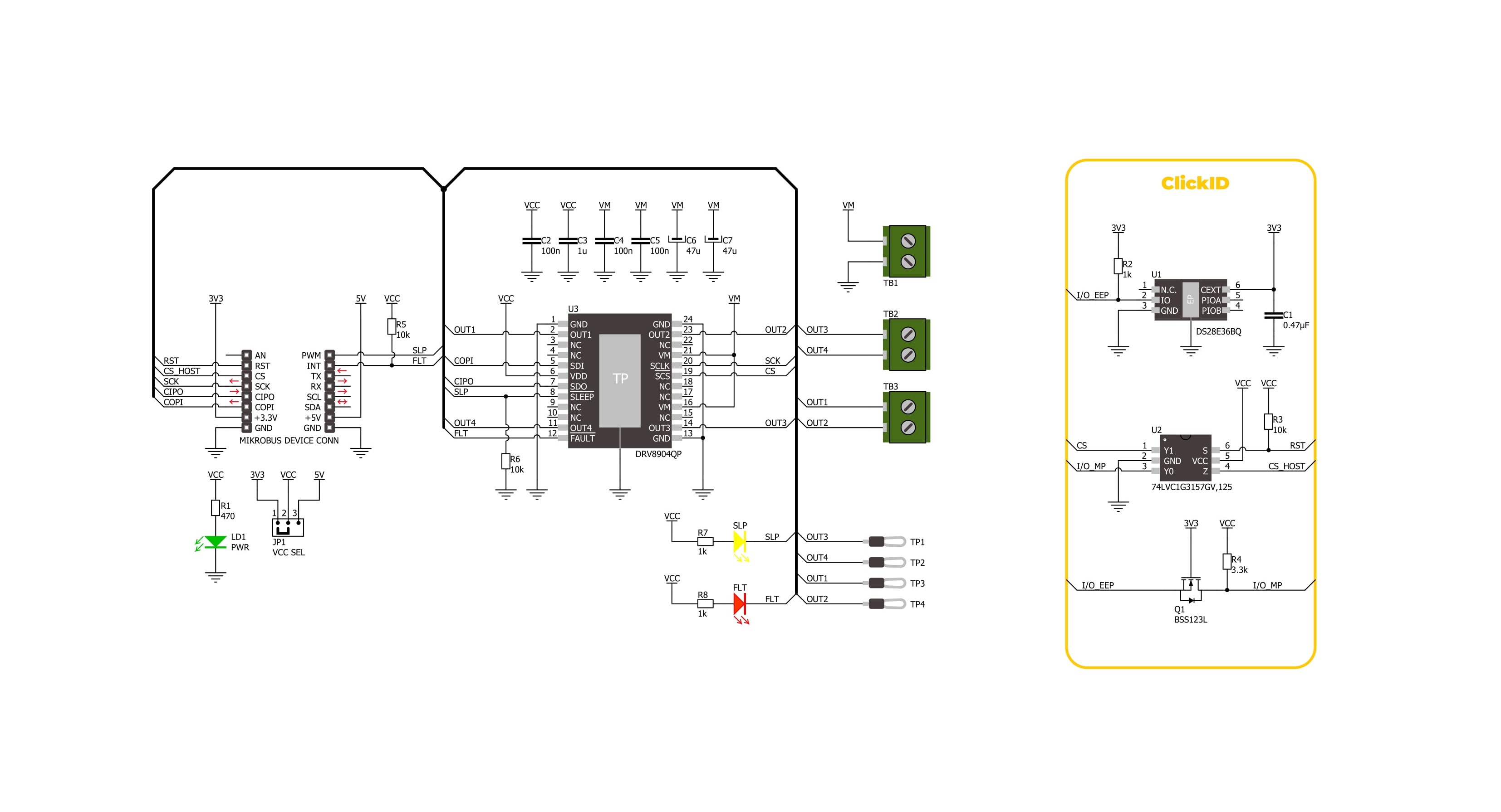
H-Bridge 18 Click is based on the DRV8904-Q1, an automotive-grade multi-channel half-bridge driver from Texas Instruments, designed for precise control of brushed DC (BDC) motors and stepper motors, offering advanced diagnostics and protection features. The DRV8904-Q1 supports independent, sequential, or parallel motor driving modes, with each half-bridge rated for a continuous output current of 1A (6A maximum current for paralleled outputs). Its architecture allows full control of motor movement, including forward, reverse, coasting, and braking operations, ensuring performance in demanding environments. Thanks to its versatile capabilities, H-Bridge 18 Click is well-suited for various automotive, industrial, and consumer electronics applications, including HVAC flap control, LED lighting, multiple brushed DC motor systems, and solenoid actuation, where precision control and system protection are critical. This Click board™ communicates with the host MCU through a standard 16-bit SPI interface. It operates at speeds of up to 5MHz and features
daisy-chain support for integration into complex systems. One of its key features is the integration of eight programmable PWM generators, allowing for precise current limiting during motor operation or controlled LED dimming. The DRV8904-Q1 also incorporates an array of diagnostic and protection mechanisms to enhance reliability. These include real-time fault monitoring and reporting, ensuring immediate detection and response to issues such as short circuits, undervoltage, or thermal overload. Additionally, the device features a low-current open-load detection (OLD) mode, which enables accurate identification of open-load conditions even when the nominal load current is minimal, alongside a passive OLD mode for offline fault detection. The H-Bridge 18 Click operates from an external power supply connected to the VM terminal, with a recommended operating range of 4.5V to 32V. In addition to the SPI interface, H-Bridge 18 Click includes dedicated control pins for enhanced power management and fault monitoring. The SLP pin allows the device to enter a low-power
Sleep mode when set to a LOW logic level while setting it to HIGH enables the driver to operate normally. Additionally, the FLT pin serves as a fault indication signal, alerting the system when an error condition is detected. To provide clear visual feedback, the board integrates corresponding LED indicators: a yellow SLEEP LED to signal when the device is in low-power mode and a red FAULT LED to indicate the presence of a detected fault, ensuring real-time status monitoring and improved system reliability. Besides the load connection terminals, the board includes four dedicated hooks that serve as test points for the attached load, allowing for convenient monitoring and diagnostics during operation. This Click board™ can operate with either 3.3V or 5V logic voltage levels selected via the VCC SEL jumper. This way, both 3.3V and 5V capable MCUs can use the communication lines properly. Also, this Click board™ comes equipped with a library containing easy-to-use functions and an example code that can be used as a reference for further development.

Features overview
Development board
6LoWPAN Clicker is a compact starter development board that brings the flexibility of add-on Click boards™ to your favorite microcontroller, making it a perfect starter kit for implementing your ideas. It comes with an onboard 32-bit PIC microcontroller, the PIC32MX470F512H from Microchip, a USB connector, LED indicators, buttons, a mikroProg connector, and a header for interfacing with external electronics. Along with this microcontroller, the board also contains a 2.4GHz ISM band transceiver, allowing you to add wireless communication to your target application. Its compact design provides a fluid and immersive working experience, allowing access anywhere
and under any circumstances. Each part of the 6LoWPAN Clicker development kit contains the components necessary for the most efficient operation of the same board. In addition to the possibility of choosing the 6LoWPAN Clicker programming method, using USB HID mikroBootloader, or through an external mikroProg connector for PIC, dsPIC, or PIC32 programmer, the Clicker board also includes a clean and regulated power supply module for the development kit. The USB Micro-B connection can provide up to 500mA of current for the Clicker board, which is more than enough to operate all onboard and additional modules, or it can power
over two standard AA batteries. All communication methods that mikroBUS™ itself supports are on this board, including the well-established mikroBUS™ socket, reset button, and several buttons and LED indicators. 6LoWPAN Clicker is an integral part of the Mikroe ecosystem, allowing you to create a new application in minutes. Natively supported by Mikroe software tools, it covers many aspects of prototyping thanks to a considerable number of different Click boards™ (over a thousand boards), the number of which is growing every day.

Microcontroller Overview
MCU Card / MCU

Architecture
PIC32
MCU Memory (KB)
512
Silicon Vendor
Microchip
Pin count
64
RAM (Bytes)
131072
You complete me!
Accessories
DC Gear Motor - 430RPM (3-6V) represents an all-in-one combination of a motor and gearbox, where the addition of gear leads to a reduction of motor speed while increasing the torque output. This gear motor has a spur gearbox, making it a highly reliable solution for applications with lower torque and speed requirements. The most critical parameters for gear motors are speed, torque, and efficiency, which are, in this case, 520RPM with no load and 430RPM at maximum efficiency, alongside a current of 60mA and a torque of 50g.cm. Rated for a 3-6V operational voltage range and clockwise/counterclockwise rotation direction, this motor represents an excellent solution for many functions initially performed by brushed DC motors in robotics, medical equipment, electric door locks, and much more.

Used MCU Pins
mikroBUS™ mapper
Take a closer look
Click board™ Schematic
Step by step
Project assembly

Start by selecting your development board and Click board™. Begin with the 6LoWPAN clicker as your development board.


Track your results in real time
Application Output
1. Application Output - In Debug mode, the 'Application Output' window enables real-time data monitoring, offering direct insight into execution results. Ensure proper data display by configuring the environment correctly using the provided tutorial.

2. UART Terminal - Use the UART Terminal to monitor data transmission via a USB to UART converter, allowing direct communication between the Click board™ and your development system. Configure the baud rate and other serial settings according to your project's requirements to ensure proper functionality. For step-by-step setup instructions, refer to the provided tutorial.

3. Plot Output - The Plot feature offers a powerful way to visualize real-time sensor data, enabling trend analysis, debugging, and comparison of multiple data points. To set it up correctly, follow the provided tutorial, which includes a step-by-step example of using the Plot feature to display Click board™ readings. To use the Plot feature in your code, use the function: plot(*insert_graph_name*, variable_name);. This is a general format, and it is up to the user to replace 'insert_graph_name' with the actual graph name and 'variable_name' with the parameter to be displayed.

Software Support
Library Description
H-Bridge 18 Click demo application is developed using the NECTO Studio, ensuring compatibility with mikroSDK's open-source libraries and tools. Designed for plug-and-play implementation and testing, the demo is fully compatible with all development, starter, and mikromedia boards featuring a mikroBUS™ socket.
Example Description
This example demonstrates the operation of the H-Bridge 18 Click board, which provides control over two DC motors using an H-Bridge driver. The application initializes the board and alternates between different motor states, including forward, reverse, coast, and braking, to demonstrate bidirectional motor control.
Key functions:
hbridge18_cfg_setup- This function initializes Click configuration structure to initial values.hbridge18_init- This function initializes all necessary pins and peripherals used for this Click board.hbridge18_default_cfg- Click Default Configuration function.hbridge18_enable_device- This function enables the H-Bridge 18 device by setting the sleep pin high.hbridge18_disable_device- This function disables the H-Bridge 18 device by setting the sleep pin low.hbridge18_set_motor_state- This function sets the motor state for the selected motor (coast, forward, reverse, brake low-side, or brake high-side).
Application Init
Initializes the logger and the H-Bridge 18 Click board. Configures the motor driver to the default settings, preparing it for operation.
Application Task
Alternates motor states in a sequence to demonstrate different control functionalities. The motors are set to move forward and reverse, followed by coasting and braking, repeating the cycle continuously.
Open Source
Code example
The complete application code and a ready-to-use project are available through the NECTO Studio Package Manager for direct installation in the NECTO Studio. The application code can also be found on the MIKROE GitHub account.
/*!
 * @file main.c
 * @brief H-Bridge 18 Click example
 *
 * # Description
 * This example demonstrates the operation of the H-Bridge 18 Click board, which
 * provides control over two DC motors using an H-Bridge driver. The application
 * initializes the board and alternates between different motor states, including
 * forward, reverse, coast, and braking, to demonstrate bidirectional motor control.
 *
 * The demo application is composed of two sections:
 *
 * ## Application Init
 * Initializes the logger and the H-Bridge 18 Click board. Configures the motor driver
 * to the default settings, preparing it for operation.
 *
 * ## Application Task
 * Alternates motor states in a sequence to demonstrate different control functionalities.
 * The motors are set to move forward and reverse, followed by coasting and braking,
 * repeating the cycle continuously.
 *
 * @note
 * Ensure proper power supply (4.5V-32V, depending on motor specifications) and motor
 * connections (motor 0: O1-O2; motor 1: O3-O4) before running the example.
 *
 * @author Stefan Filipovic
 *
 */

#include "board.h"
#include "log.h"
#include "hbridge18.h"

static hbridge18_t hbridge18;
static log_t logger;

void application_init ( void )
{
    log_cfg_t log_cfg;  /**< Logger config object. */
    hbridge18_cfg_t hbridge18_cfg;  /**< Click config object. */

    /**
     * Logger initialization.
     * Default baud rate: 115200
     * Default log level: LOG_LEVEL_DEBUG
     * @note If USB_UART_RX and USB_UART_TX
     * are defined as HAL_PIN_NC, you will
     * need to define them manually for log to work.
     * See @b LOG_MAP_USB_UART macro definition for detailed explanation.
     */
    LOG_MAP_USB_UART( log_cfg );
    log_init( &logger, &log_cfg );
    log_info( &logger, " Application Init " );

    // Click initialization.
    hbridge18_cfg_setup( &hbridge18_cfg );
    HBRIDGE18_MAP_MIKROBUS( hbridge18_cfg, MIKROBUS_1 );
    if ( SPI_MASTER_ERROR == hbridge18_init( &hbridge18, &hbridge18_cfg ) )
    {
        log_error( &logger, " Communication init." );
        for ( ; ; );
    }

    if ( HBRIDGE18_ERROR == hbridge18_default_cfg ( &hbridge18 ) )
    {
        log_error( &logger, " Default configuration." );
        for ( ; ; );
    }

    log_info( &logger, " Application Task " );
}

void application_task ( void )
{
    log_printf( &logger, " Motor 0: Forward\r\n" );
    log_printf( &logger, " Motor 1: Reverse\r\n\n" );
    hbridge18_set_motor_state ( &hbridge18, HBRIDGE18_MOTOR_0, HBRIDGE18_MOTOR_STATE_FORWARD );
    hbridge18_set_motor_state ( &hbridge18, HBRIDGE18_MOTOR_1, HBRIDGE18_MOTOR_STATE_REVERSE );
    Delay_ms ( 1000 );
    Delay_ms ( 1000 );
    log_printf( &logger, " Motor 0: Coast\r\n" );
    log_printf( &logger, " Motor 1: Brake LS\r\n\n" );
    hbridge18_set_motor_state ( &hbridge18, HBRIDGE18_MOTOR_0, HBRIDGE18_MOTOR_STATE_COAST );
    hbridge18_set_motor_state ( &hbridge18, HBRIDGE18_MOTOR_1, HBRIDGE18_MOTOR_STATE_BRAKE_LS );
    Delay_ms ( 1000 );
    Delay_ms ( 1000 );
    log_printf( &logger, " Motor 0: Reverse\r\n" );
    log_printf( &logger, " Motor 1: Forward\r\n\n" );
    hbridge18_set_motor_state ( &hbridge18, HBRIDGE18_MOTOR_0, HBRIDGE18_MOTOR_STATE_REVERSE );
    hbridge18_set_motor_state ( &hbridge18, HBRIDGE18_MOTOR_1, HBRIDGE18_MOTOR_STATE_FORWARD );
    Delay_ms ( 1000 );
    Delay_ms ( 1000 );
    log_printf( &logger, " Motor 0: Brake HS\r\n" );
    log_printf( &logger, " Motor 1: Coast\r\n\n" );
    hbridge18_set_motor_state ( &hbridge18, HBRIDGE18_MOTOR_0, HBRIDGE18_MOTOR_STATE_BRAKE_HS );
    hbridge18_set_motor_state ( &hbridge18, HBRIDGE18_MOTOR_1, HBRIDGE18_MOTOR_STATE_COAST );
    Delay_ms ( 1000 );
    Delay_ms ( 1000 );
}

int main ( void )
{
    /* Do not remove this line or clock might not be set correctly. */
    #ifdef PREINIT_SUPPORTED
    preinit();
    #endif

    application_init( );

    for ( ; ; )
    {
        application_task( );
    }

    return 0;
}

// ------------------------------------------------------------------------ END
Additional Support
Resources
Category:Brushed