Provide long-range LTE-M and NB-IoT connectivity with built-in GNSS using the HL7812 and STM32G474RE
Multi-protocol LTE-M/NB-IoT with GNSS for reliable, low-power cellular IoT applications
Published Oct 22, 2025
Click board™
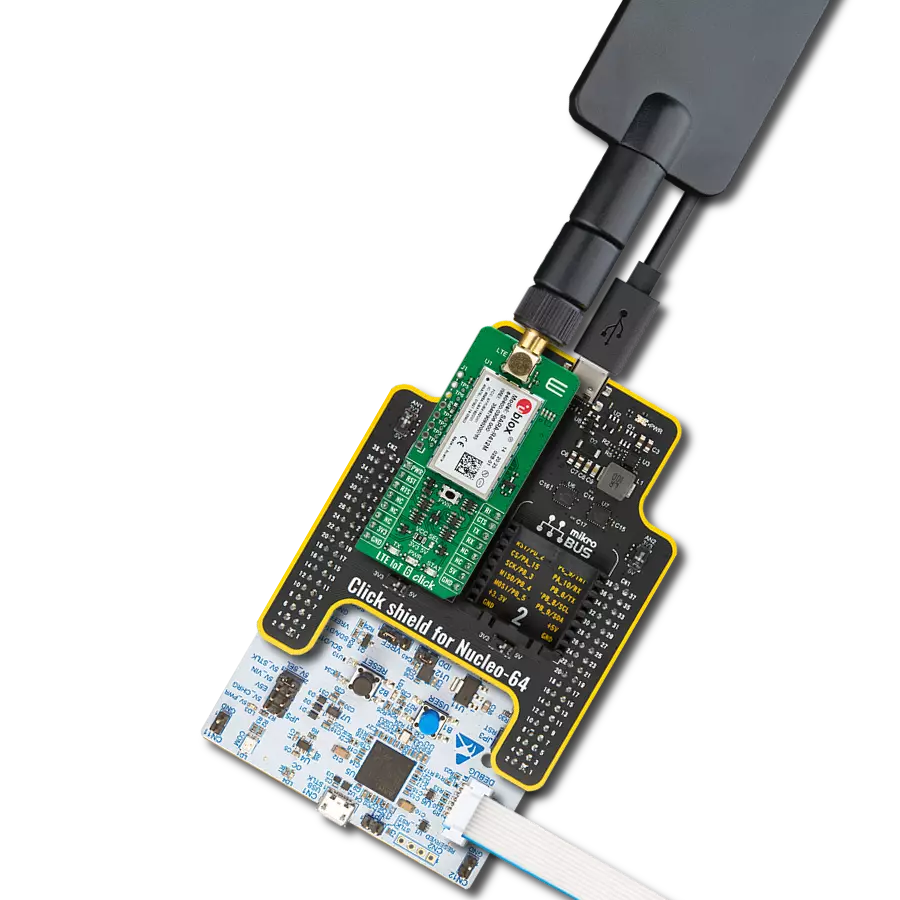
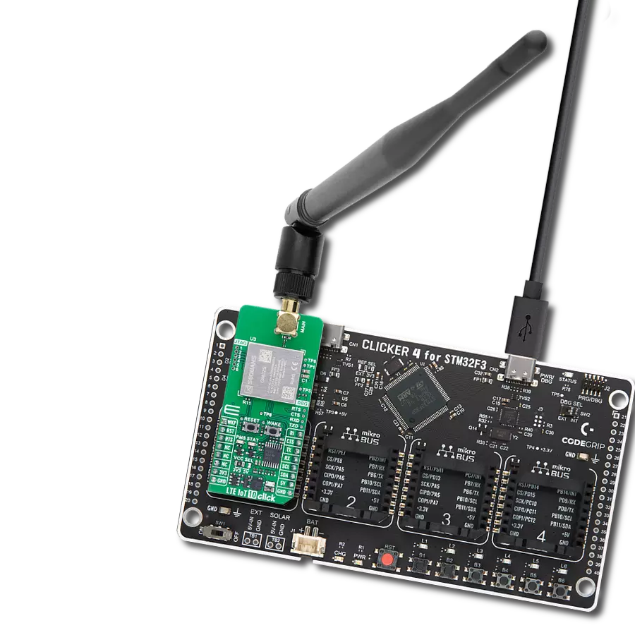
LTE IoT 19 Click
Dev. board
Nucleo 64 with STM32G474RE MCU
Compiler
NECTO Studio
MCU
STM32G474RE
Add secure, low-power cellular communication with 2G fallback to industrial and mission-critical IoT devices
A
A
Hardware Overview
How does it work?
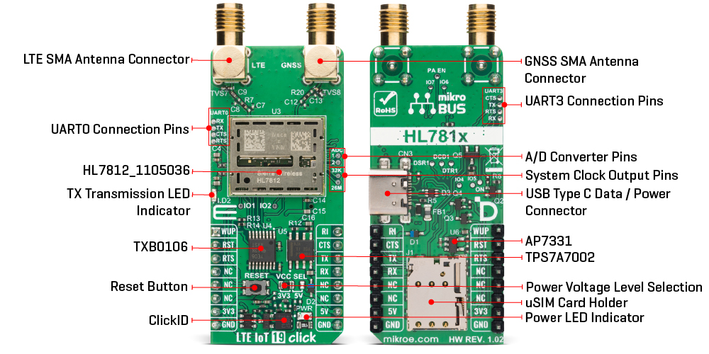
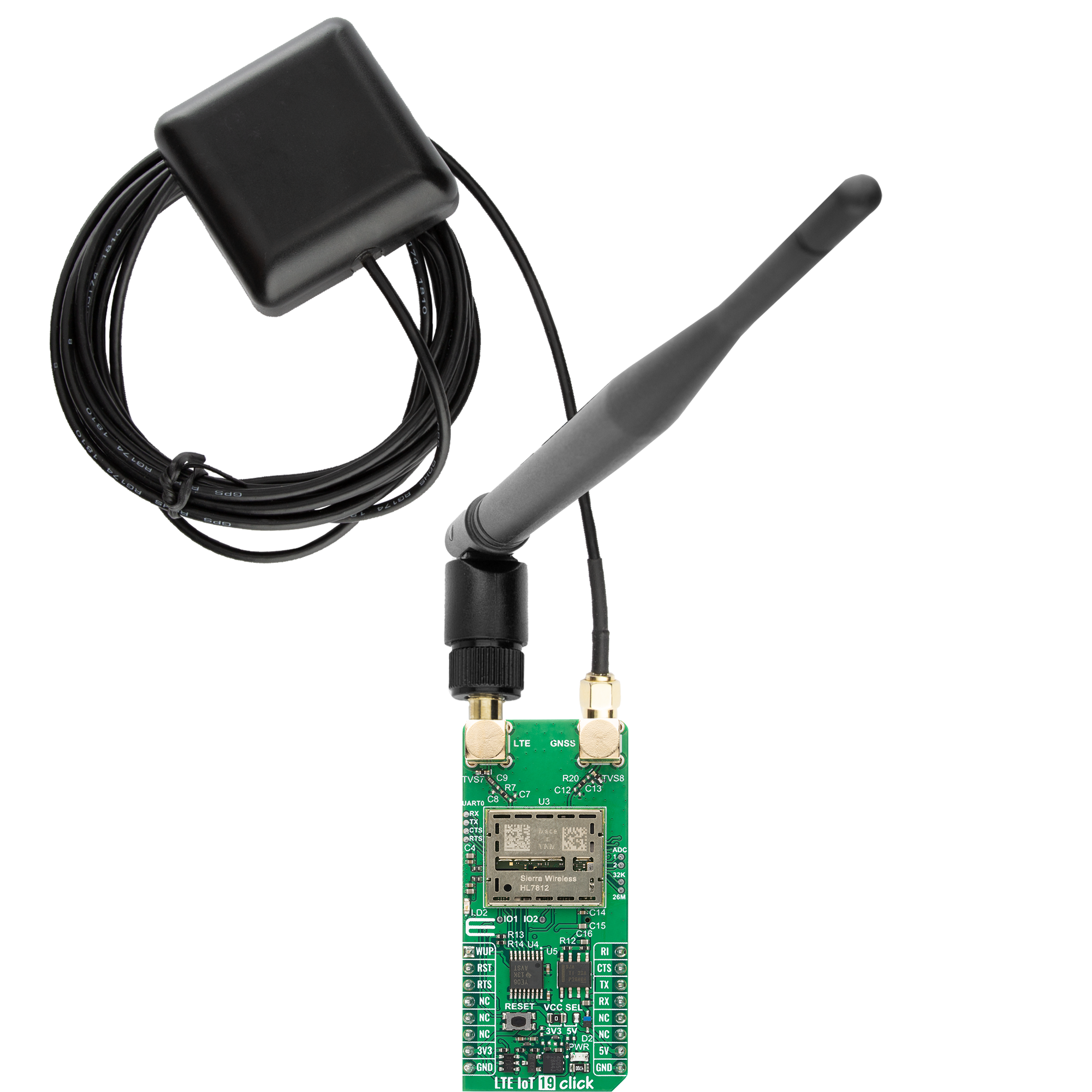
LTE IoT 19 Click is based on the HL7812, a global Low Power Wide Area (LPWA) cellular module from Semtech that combines LTE-M, NB-IoT, and 2G fallback designed for industrial and mission-critical IoT. This module delivers best-in-class power consumption, high transmit power, and deep coverage for remote or battery-powered deployments, meeting 3GPP Release 14 requirements and ensuring future-proof connectivity for long-lived field devices. By integrating support for LTE Cat-M1 and Cat-NB2 together with quad-band 2G GPRS, the HL7812 offers connectivity across different radio access technologies with flexible manual or dynamic system selection, enabling reliable operation even in challenging environments. Its industry-leading security from the edge to the cloud, and extended coverage features like Power Save Mode, extended Discontinuous Reception (eDRX), and Release Assistance Indication make it ideal for asset tracking, smart metering, smart city infrastructure, and any application where energy efficiency, robust connectivity, and longevity are paramount. The HL7812 integrates advanced RF and protocol capabilities that maximize performance and versatility. It provides high transmit power across 850/900/1800/1900MHz for 2G and Class 3 (23dBm) operation for both Cat-M1 and Cat-NB2, ensuring strong links even at cell edges. LTE Cat-M1 supports uplink speeds up to 1100kbit/s and downlink up to 590kbit/s, while Cat-NB2 supports
up to 158kbit/s uplink and 127kbit/s downlink, all with 3GPP Rel.14 features like HARQ-ACK bundling, multiple HARQ processes, and Control Plane CIoT optimization. The module also incorporates built-in GNSS (GPS and GLONASS) for precise positioning and tracking, plus features like NIDD over SCEF/SGi tunneling, idle and connected mobility, and operational modes for in-band, guard band, or standalone deployments. Communication between the HL7812 and the host MCU is made through a UART interface, using standard UART RX and TX pins and hardware flow control pins (CTS/RTS/RI - Clear to Send/Ready to Send/Ring Indicator) for efficient data transfer. The module defaults to a communication speed of 115200bps, allowing for data exchange over AT commands. This Click board™ also includes a USB Type C connector for both power and data transfer, compliant with the USB 2.0 specification. The board also includes several additional functionalities that enhance its usability and control. The RESET button allows users to easily reset the module. This function can also be controlled digitally via the mikroBUS™ RST pin, offering greater flexibility. In addition to the primary UART interface used for standard data communication, the board provides dedicated pins for a debug UART (UART0), which is intended for firmware debugging and upgrading. It further includes an auxiliary UART (UART3) that allows flexible use of AT command communication and data transmission, giving developers extended
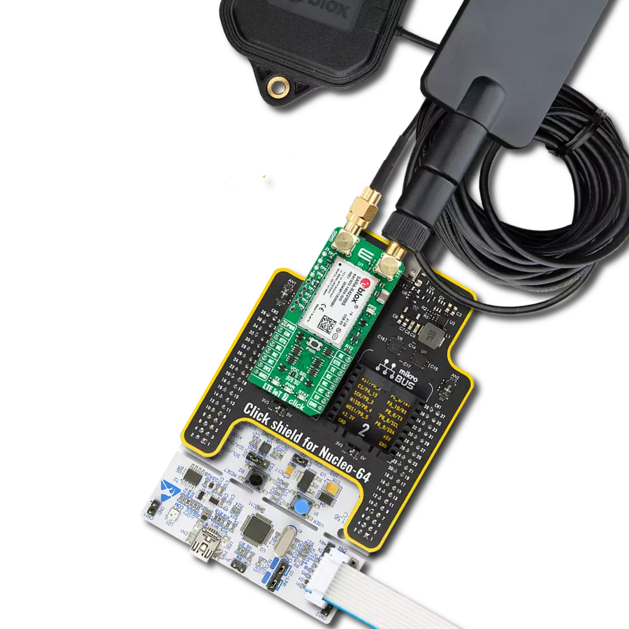
control and connectivity options within their applications. The board features SMA connectors for LTE antenna (LTE Flat Rotation Antenna) and one for GNSS such as the GPS Passive Antenna offered by MIKROE, ensuring efficient connectivity options. The board also has a micro SIM card holder that supports both 1.8V and 3V uSIM cards, allowing users to select the most appropriate service provider for their particular use case, and one blue LED indicator for TX activity indication. There is also a set of test points labeled ADC, providing access to the HL7812 module’s 12-bit resolution analog-to-digital converter channels with a voltage range of 0–1.8 V for monitoring external signals, as well as 32K and 26M test points which expose two digital clock output signals for timing or diagnostic purposes. This Click board™ can operate with both 3.3V and 5V logic voltage levels selected via the VCC SEL jumper. Since the HL7812 module operates at 4.07V and communicates at 1.8V, a logic-level translator, the TXB0106 is also used for proper operation and an accurate signal-level translation. This way, both 3.3V and 5V capable MCUs can use the communication lines properly. Also, this Click board™ comes equipped with a library containing easy-to-use functions and an example code that can be used as a reference for further development.
Features overview
Development board
Nucleo-64 with STM32G474R MCU offers a cost-effective and adaptable platform for developers to explore new ideas and prototype their designs. This board harnesses the versatility of the STM32 microcontroller, enabling users to select the optimal balance of performance and power consumption for their projects. It accommodates the STM32 microcontroller in the LQFP64 package and includes essential components such as a user LED, which doubles as an ARDUINO® signal, alongside user and reset push-buttons, and a 32.768kHz crystal oscillator for precise timing operations. Designed with expansion and flexibility in mind, the Nucleo-64 board features an ARDUINO® Uno V3 expansion connector and ST morpho extension pin
headers, granting complete access to the STM32's I/Os for comprehensive project integration. Power supply options are adaptable, supporting ST-LINK USB VBUS or external power sources, ensuring adaptability in various development environments. The board also has an on-board ST-LINK debugger/programmer with USB re-enumeration capability, simplifying the programming and debugging process. Moreover, the board is designed to simplify advanced development with its external SMPS for efficient Vcore logic supply, support for USB Device full speed or USB SNK/UFP full speed, and built-in cryptographic features, enhancing both the power efficiency and security of projects. Additional connectivity is
provided through dedicated connectors for external SMPS experimentation, a USB connector for the ST-LINK, and a MIPI® debug connector, expanding the possibilities for hardware interfacing and experimentation. Developers will find extensive support through comprehensive free software libraries and examples, courtesy of the STM32Cube MCU Package. This, combined with compatibility with a wide array of Integrated Development Environments (IDEs), including IAR Embedded Workbench®, MDK-ARM, and STM32CubeIDE, ensures a smooth and efficient development experience, allowing users to fully leverage the capabilities of the Nucleo-64 board in their projects.

Microcontroller Overview
MCU Card / MCU

Architecture
ARM Cortex-M4
MCU Memory (KB)
512
Silicon Vendor
STMicroelectronics
Pin count
64
RAM (Bytes)
128k
You complete me!
Accessories
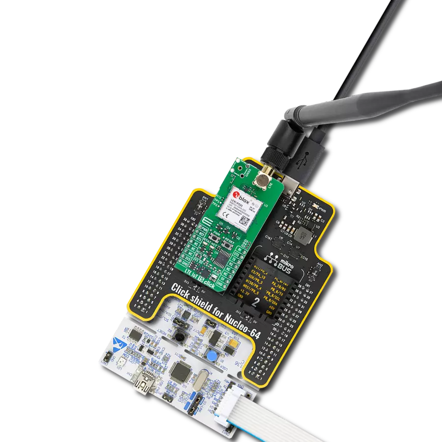
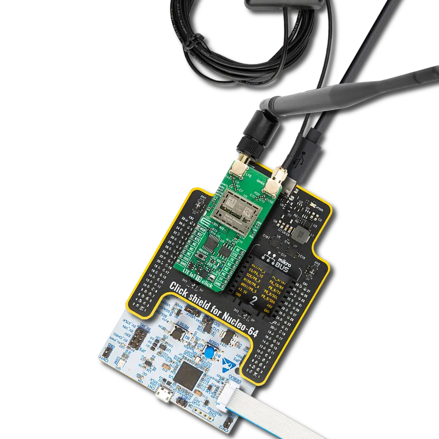
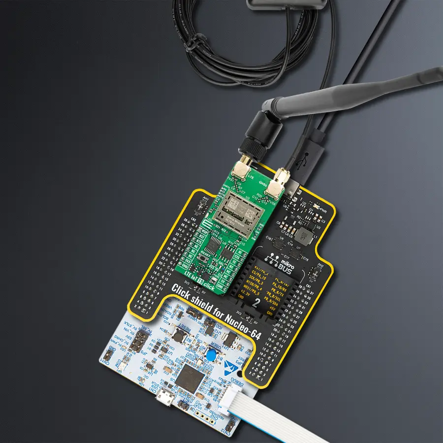
Click Shield for Nucleo-64 comes equipped with two proprietary mikroBUS™ sockets, allowing all the Click board™ devices to be interfaced with the STM32 Nucleo-64 board with no effort. This way, Mikroe allows its users to add any functionality from our ever-growing range of Click boards™, such as WiFi, GSM, GPS, Bluetooth, ZigBee, environmental sensors, LEDs, speech recognition, motor control, movement sensors, and many more. More than 1537 Click boards™, which can be stacked and integrated, are at your disposal. The STM32 Nucleo-64 boards are based on the microcontrollers in 64-pin packages, a 32-bit MCU with an ARM Cortex M4 processor operating at 84MHz, 512Kb Flash, and 96KB SRAM, divided into two regions where the top section represents the ST-Link/V2 debugger and programmer while the bottom section of the board is an actual development board. These boards are controlled and powered conveniently through a USB connection to program and efficiently debug the Nucleo-64 board out of the box, with an additional USB cable connected to the USB mini port on the board. Most of the STM32 microcontroller pins are brought to the IO pins on the left and right edge of the board, which are then connected to two existing mikroBUS™ sockets. This Click Shield also has several switches that perform functions such as selecting the logic levels of analog signals on mikroBUS™ sockets and selecting logic voltage levels of the mikroBUS™ sockets themselves. Besides, the user is offered the possibility of using any Click board™ with the help of existing bidirectional level-shifting voltage translators, regardless of whether the Click board™ operates at a 3.3V or 5V logic voltage level. Once you connect the STM32 Nucleo-64 board with our Click Shield for Nucleo-64, you can access hundreds of Click boards™, working with 3.3V or 5V logic voltage levels.

Used MCU Pins
mikroBUS™ mapper
Take a closer look
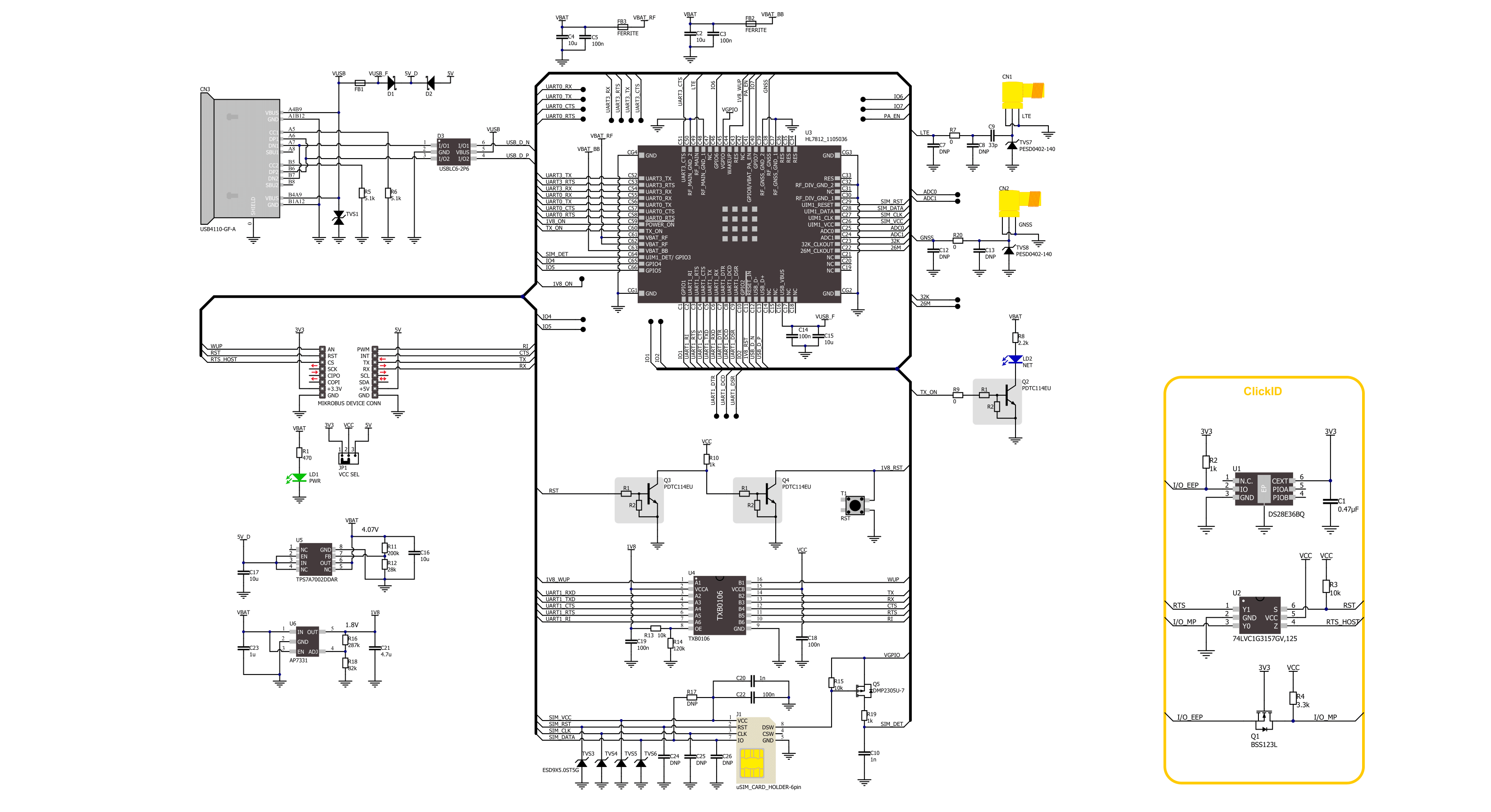
Click board™ Schematic
Step by step
Project assembly
Start by selecting your development board and Click board™. Begin with the Nucleo 64 with STM32G474RE MCU as your development board.


Software Support
Library Description
LTE IoT 19 Click demo application is developed using the NECTO Studio, ensuring compatibility with mikroSDK's open-source libraries and tools. Designed for plug-and-play implementation and testing, the demo is fully compatible with all development, starter, and mikromedia boards featuring a mikroBUS™ socket.
Example Description
Application example shows device capability of connecting to the network and sending SMS or TCP/UDP messages or retrieving data from GNSS using standard "AT" commands.
Key functions:
lteiot19_cfg_setup- This function initializes Click configuration structure to initial values.lteiot19_init- This function initializes all necessary pins and peripherals used for this Click board.lteiot19_set_sim_apn- This function sets APN for sim card.lteiot19_send_sms_text- This function sends text message to a phone number.lteiot19_cmd_run- This function sends a specified command to the Click module.
Application Init
Initializes the driver and logger.
Application Task
Application task is split in few stages:
LTEIOT19_POWER_UP- Powers up the device, performs a factory reset and reads system information.LTEIOT19_CONFIG_CONNECTION- Sets configuration to device to be able to connect to the network (used only for SMS or TCP/UDP demo examples).LTEIOT19_CHECK_CONNECTION- Waits for the network registration indicated via CEREG command and then checks the signal quality report (used only for SMS or TCP/UDP demo examples).LTEIOT19_CONFIG_EXAMPLE- Configures device for the selected example.LTEIOT19_EXAMPLE- Depending on the selected demo example, it sends an SMS message (in PDU or TXT mode) or TCP/UDP message, or waits for the GPS fix to retrieve location info from GNSS. By default, the TCP/UDP example is selected.
Open Source
Code example
The complete application code and a ready-to-use project are available through the NECTO Studio Package Manager for direct installation in the NECTO Studio. The application code can also be found on the MIKROE GitHub account.
/*!
* @file main.c
* @brief LTE IoT 19 Click Example.
*
* # Description
* Application example shows device capability of connecting to the network and
* sending SMS or TCP/UDP messages or retrieving data from GNSS using standard "AT" commands.
*
* The demo application is composed of two sections :
*
* ## Application Init
* Initializes the driver and logger.
*
* ## Application Task
* Application task is split in few stages:
* - LTEIOT19_POWER_UP:
* Powers up the device, performs a factory reset and reads system information.
*
* - LTEIOT19_CONFIG_CONNECTION:
* Sets configuration to device to be able to connect to the network
* (used only for SMS or TCP/UDP demo examples).
*
* - LTEIOT19_CHECK_CONNECTION:
* Waits for the network registration indicated via CEREG command and then checks
* the signal quality report (used only for SMS or TCP/UDP demo examples).
*
* - LTEIOT19_CONFIG_EXAMPLE:
* Configures device for the selected example.
*
* - LTEIOT19_EXAMPLE:
* Depending on the selected demo example, it sends an SMS message (in PDU or TXT mode)
* or TCP/UDP message, or waits for the GPS fix to retrieve location info from GNSS.
*
* By default, the TCP/UDP example is selected.
*
* ## Additional Function
* - static void lteiot19_clear_app_buf ( void )
* - static void lteiot19_log_app_buf ( void )
* - static err_t lteiot19_process ( lteiot19_t *ctx )
* - static err_t lteiot19_read_response ( lteiot19_t *ctx, uint8_t *rsp, uint32_t max_rsp_time )
* - static err_t lteiot19_power_up ( lteiot19_t *ctx )
* - static err_t lteiot19_config_connection ( lteiot19_t *ctx )
* - static err_t lteiot19_check_connection ( lteiot19_t *ctx )
* - static err_t lteiot19_config_example ( lteiot19_t *ctx )
* - static err_t lteiot19_example ( lteiot19_t *ctx )
*
* @note
* In order for the examples to work (except GNSS example), user needs to set the APN and SMSC (SMS PDU mode only)
* of entered SIM card as well as the phone number (SMS mode only) to which he wants to send an SMS.
* Enter valid values for the following macros: SIM_APN, SIM_SMSC and PHONE_NUMBER.
* Example:
SIM_APN "internet"
SIM_SMSC "+381610401"
PHONE_NUMBER "+381659999999"
*
* @author Stefan Filipovic
*
*/
#include "board.h"
#include "log.h"
#include "lteiot19.h"
#include "conversions.h"
// Example selection macros
#define EXAMPLE_TCP_UDP 0 // Example of sending messages to a TCP/UDP echo server
#define EXAMPLE_SMS 1 // Example of sending SMS to a phone number
#define EXAMPLE_GNSS 2 // Example of retrieving location info from GNSS
#define DEMO_EXAMPLE EXAMPLE_TCP_UDP // Example selection macro
// SIM APN config
#define SIM_APN "" // Set valid SIM APN
// SMS example parameters
#define SIM_SMSC "" // Set valid SMS Service Center Address - only in SMS PDU mode
#define PHONE_NUMBER "" // Set Phone number to message
#define SMS_MODE "1" // SMS mode: "0" - PDU, "1" - TXT
// TCP/UDP example parameters
#define REMOTE_IP "54.187.244.144"// TCP/UDP echo server IP address
#define REMOTE_PORT "51111" // TCP/UDP echo server port
// Message content
#define MESSAGE_CONTENT "LTE IoT 19 Click board - demo example."
// Application buffer size
#define APP_BUFFER_SIZE 256
#define PROCESS_BUFFER_SIZE 256
/**
* @brief Example states.
* @details Predefined enum values for application example state.
*/
typedef enum
{
LTEIOT19_POWER_UP = 1,
LTEIOT19_CONFIG_CONNECTION,
LTEIOT19_CHECK_CONNECTION,
LTEIOT19_CONFIG_EXAMPLE,
LTEIOT19_EXAMPLE
} lteiot19_app_state_t;
/**
* @brief Application example variables.
* @details Variables used in application example.
*/
static uint8_t app_buf[ APP_BUFFER_SIZE ] = { 0 };
static int32_t app_buf_len = 0;
static lteiot19_app_state_t app_state = LTEIOT19_POWER_UP;
static lteiot19_t lteiot19;
static log_t logger;
/**
* @brief LTE IoT 19 clearing application buffer.
* @details This function clears memory of application buffer and reset its length.
* @note None.
*/
static void lteiot19_clear_app_buf ( void );
/**
* @brief LTE IoT 19 log application buffer.
* @details This function logs data from application buffer to USB UART.
* @note None.
*/
static void lteiot19_log_app_buf ( void );
/**
* @brief LTE IoT 19 data reading function.
* @details This function reads data from device and concatenates data to application buffer.
* @param[in] ctx : Click context object.
* See #lteiot19_t object definition for detailed explanation.
* @return @li @c 0 - Read some data.
* @li @c -1 - Nothing is read.
* See #err_t definition for detailed explanation.
* @note None.
*/
static err_t lteiot19_process ( lteiot19_t *ctx );
/**
* @brief LTE IoT 19 read response function.
* @details This function waits for a response message, reads and displays it on the USB UART.
* @param[in] ctx : Click context object.
* See #lteiot19_t object definition for detailed explanation.
* @param[in] rsp Expected response.
* @param[in] max_rsp_time : Maximum response time in milliseconds.
* @return @li @c 0 - OK response.
* @li @c -2 - Timeout error.
* @li @c -3 - Command error.
* See #err_t definition for detailed explanation.
* @note None.
*/
static err_t lteiot19_read_response ( lteiot19_t *ctx, uint8_t *rsp, uint32_t max_rsp_time );
/**
* @brief LTE IoT 19 power up function.
* @details This function powers up the device, performs a factory reset and reads system information.
* @param[in] ctx : Click context object.
* See #lteiot19_t object definition for detailed explanation.
* @return @li @c 0 - OK.
* @li @c != 0 - Read response error.
* See #err_t definition for detailed explanation.
* @note None.
*/
static err_t lteiot19_power_up ( lteiot19_t *ctx );
/**
* @brief LTE IoT 19 config connection function.
* @details This function configures and enables connection to the specified network.
* @param[in] ctx : Click context object.
* See #lteiot19_t object definition for detailed explanation.
* @return @li @c 0 - OK.
* @li @c != 0 - Read response error.
* See #err_t definition for detailed explanation.
* @note None.
*/
static err_t lteiot19_config_connection ( lteiot19_t *ctx );
/**
* @brief LTE IoT 19 check connection function.
* @details This function checks the connection to network.
* @param[in] ctx : Click context object.
* See #lteiot19_t object definition for detailed explanation.
* @return @li @c 0 - OK.
* @li @c != 0 - Read response error.
* See #err_t definition for detailed explanation.
* @note None.
*/
static err_t lteiot19_check_connection ( lteiot19_t *ctx );
/**
* @brief LTE IoT 19 config example function.
* @details This function configures device for the selected example.
* @param[in] ctx : Click context object.
* See #lteiot19_t object definition for detailed explanation.
* @return @li @c 0 - OK.
* @li @c != 0 - Read response error.
* See #err_t definition for detailed explanation.
* @note None.
*/
static err_t lteiot19_config_example ( lteiot19_t *ctx );
/**
* @brief LTE IoT 19 example function.
* @details This function executes SMS, TCP/UDP, or GNSS example depending on the DEMO_EXAMPLE macro.
* @param[in] ctx : Click context object.
* See #lteiot19_t object definition for detailed explanation.
* @return @li @c 0 - OK.
* @li @c != 0 - Read response error.
* See #err_t definition for detailed explanation.
* @note None.
*/
static err_t lteiot19_example ( lteiot19_t *ctx );
void application_init ( void )
{
log_cfg_t log_cfg; /**< Logger config object. */
lteiot19_cfg_t lteiot19_cfg; /**< Click config object. */
/**
* Logger initialization.
* Default baud rate: 115200
* Default log level: LOG_LEVEL_DEBUG
* @note If USB_UART_RX and USB_UART_TX
* are defined as HAL_PIN_NC, you will
* need to define them manually for log to work.
* See @b LOG_MAP_USB_UART macro definition for detailed explanation.
*/
LOG_MAP_USB_UART( log_cfg );
log_init( &logger, &log_cfg );
log_info( &logger, " Application Init " );
// Click initialization.
lteiot19_cfg_setup( <eiot19_cfg );
LTEIOT19_MAP_MIKROBUS( lteiot19_cfg, MIKROBUS_1 );
if ( UART_ERROR == lteiot19_init( <eiot19, <eiot19_cfg ) )
{
log_error( &logger, " Communication init." );
for ( ; ; );
}
log_info( &logger, " Application Task " );
app_state = LTEIOT19_POWER_UP;
log_printf( &logger, ">>> APP STATE - POWER UP <<<\r\n\n" );
}
void application_task ( void )
{
switch ( app_state )
{
case LTEIOT19_POWER_UP:
{
if ( LTEIOT19_OK == lteiot19_power_up( <eiot19 ) )
{
app_state = LTEIOT19_CONFIG_CONNECTION;
log_printf( &logger, ">>> APP STATE - CONFIG CONNECTION <<<\r\n\n" );
}
break;
}
case LTEIOT19_CONFIG_CONNECTION:
{
if ( LTEIOT19_OK == lteiot19_config_connection( <eiot19 ) )
{
app_state = LTEIOT19_CHECK_CONNECTION;
log_printf( &logger, ">>> APP STATE - CHECK CONNECTION <<<\r\n\n" );
}
break;
}
case LTEIOT19_CHECK_CONNECTION:
{
if ( LTEIOT19_OK == lteiot19_check_connection( <eiot19 ) )
{
app_state = LTEIOT19_CONFIG_EXAMPLE;
log_printf( &logger, ">>> APP STATE - CONFIG EXAMPLE <<<\r\n\n" );
}
break;
}
case LTEIOT19_CONFIG_EXAMPLE:
{
if ( LTEIOT19_OK == lteiot19_config_example( <eiot19 ) )
{
app_state = LTEIOT19_EXAMPLE;
log_printf( &logger, ">>> APP STATE - EXAMPLE <<<\r\n\n" );
}
break;
}
case LTEIOT19_EXAMPLE:
{
lteiot19_example( <eiot19 );
break;
}
default:
{
log_error( &logger, " APP STATE." );
break;
}
}
}
int main ( void )
{
/* Do not remove this line or clock might not be set correctly. */
#ifdef PREINIT_SUPPORTED
preinit();
#endif
application_init( );
for ( ; ; )
{
application_task( );
}
return 0;
}
static void lteiot19_clear_app_buf ( void )
{
memset( app_buf, 0, app_buf_len );
app_buf_len = 0;
}
static void lteiot19_log_app_buf ( void )
{
for ( int32_t buf_cnt = 0; buf_cnt < app_buf_len; buf_cnt++ )
{
log_printf( &logger, "%c", app_buf[ buf_cnt ] );
}
}
static err_t lteiot19_process ( lteiot19_t *ctx )
{
uint8_t rx_buf[ PROCESS_BUFFER_SIZE ] = { 0 };
int32_t overflow_bytes = 0;
int32_t rx_cnt = 0;
int32_t rx_size = lteiot19_generic_read( ctx, rx_buf, PROCESS_BUFFER_SIZE );
if ( ( rx_size > 0 ) && ( rx_size <= APP_BUFFER_SIZE ) )
{
if ( ( app_buf_len + rx_size ) > APP_BUFFER_SIZE )
{
overflow_bytes = ( app_buf_len + rx_size ) - APP_BUFFER_SIZE;
app_buf_len = APP_BUFFER_SIZE - rx_size;
for ( int32_t buf_cnt = 0; buf_cnt < overflow_bytes; buf_cnt++ )
{
log_printf( &logger, "%c", app_buf[ buf_cnt ] );
}
memmove ( app_buf, &app_buf[ overflow_bytes ], app_buf_len );
memset ( &app_buf[ app_buf_len ], 0, overflow_bytes );
}
for ( rx_cnt = 0; rx_cnt < rx_size; rx_cnt++ )
{
if ( rx_buf[ rx_cnt ] )
{
app_buf[ app_buf_len++ ] = rx_buf[ rx_cnt ];
}
}
return LTEIOT19_OK;
}
return LTEIOT19_ERROR;
}
static err_t lteiot19_read_response ( lteiot19_t *ctx, uint8_t *rsp, uint32_t max_rsp_time )
{
uint32_t timeout_cnt = 0;
lteiot19_clear_app_buf ( );
lteiot19_process( ctx );
while ( ( 0 == strstr( app_buf, rsp ) ) &&
( 0 == strstr( app_buf, LTEIOT19_RSP_ERROR ) ) )
{
lteiot19_process( ctx );
if ( timeout_cnt++ > max_rsp_time )
{
lteiot19_log_app_buf( );
lteiot19_clear_app_buf( );
log_error( &logger, " Timeout!" );
log_printf( &logger, "--------------------------------\r\n" );
return LTEIOT19_ERROR_TIMEOUT;
}
Delay_ms( 1 );
}
Delay_ms ( 200 );
lteiot19_process( ctx );
lteiot19_log_app_buf( );
log_printf( &logger, "--------------------------------\r\n" );
if ( strstr( app_buf, rsp ) )
{
return LTEIOT19_OK;
}
return LTEIOT19_ERROR_CMD;
}
static err_t lteiot19_power_up ( lteiot19_t *ctx )
{
err_t error_flag = LTEIOT19_ERROR;
while ( LTEIOT19_OK != error_flag )
{
log_printf( &logger, ">>> Reset device.\r\n" );
lteiot19_set_power_state ( ctx, LTEIOT19_POWER_STATE_RESET );
log_printf( &logger, ">>> Check communication.\r\n" );
lteiot19_cmd_run( ctx, LTEIOT19_CMD_AT );
error_flag = lteiot19_read_response( ctx, LTEIOT19_RSP_OK, LTEIOT19_MAX_RSP_TIME_DEFAULT );
}
log_printf( &logger, ">>> Get device model ID.\r\n" );
lteiot19_cmd_run( ctx, LTEIOT19_CMD_GET_MODEL_ID );
error_flag |= lteiot19_read_response( ctx, LTEIOT19_RSP_OK, LTEIOT19_MAX_RSP_TIME_DEFAULT );
log_printf( &logger, ">>> Get device software version ID.\r\n" );
lteiot19_cmd_run( ctx, LTEIOT19_CMD_GET_SW_VERSION );
error_flag |= lteiot19_read_response( ctx, LTEIOT19_RSP_OK, LTEIOT19_MAX_RSP_TIME_DEFAULT );
log_printf( &logger, ">>> Get device serial number.\r\n" );
lteiot19_cmd_run( ctx, LTEIOT19_CMD_GET_SERIAL_NUM );
error_flag |= lteiot19_read_response( ctx, LTEIOT19_RSP_OK, LTEIOT19_MAX_RSP_TIME_DEFAULT );
return error_flag;
}
static err_t lteiot19_config_connection ( lteiot19_t *ctx )
{
err_t error_flag = LTEIOT19_OK;
#if ( ( DEMO_EXAMPLE == EXAMPLE_TCP_UDP ) || ( DEMO_EXAMPLE == EXAMPLE_SMS ) )
log_printf( &logger, ">>> Set minimum functionality.\r\n" );
#define MIN_FUNCTIONALITY "0"
lteiot19_cmd_set( ctx, LTEIOT19_CMD_SET_UE_FUNCTIONALITY, MIN_FUNCTIONALITY );
error_flag |= lteiot19_read_response( ctx, LTEIOT19_RSP_OK, LTEIOT19_MAX_RSP_TIME_CFUN );
log_printf( &logger, ">>> Set SIM APN.\r\n" );
lteiot19_set_sim_apn( ctx, SIM_APN );
error_flag |= lteiot19_read_response( ctx, LTEIOT19_RSP_OK, LTEIOT19_MAX_RSP_TIME_CGDCONT );
log_printf( &logger, ">>> Enable full functionality.\r\n" );
#define FULL_FUNCTIONALITY "1"
lteiot19_cmd_set( ctx, LTEIOT19_CMD_SET_UE_FUNCTIONALITY, FULL_FUNCTIONALITY );
error_flag |= lteiot19_read_response( ctx, LTEIOT19_RSP_OK, LTEIOT19_MAX_RSP_TIME_CFUN );
log_printf( &logger, ">>> Enable network registration.\r\n" );
#define ENABLE_REG "2"
lteiot19_cmd_set( ctx, LTEIOT19_CMD_NETWORK_REGISTRATION, ENABLE_REG );
error_flag |= lteiot19_read_response( ctx, LTEIOT19_RSP_OK, LTEIOT19_MAX_RSP_TIME_DEFAULT );
#endif
return error_flag;
}
static err_t lteiot19_check_connection ( lteiot19_t *ctx )
{
err_t error_flag = LTEIOT19_OK;
#if ( ( DEMO_EXAMPLE == EXAMPLE_TCP_UDP ) || ( DEMO_EXAMPLE == EXAMPLE_SMS ) )
log_printf( &logger, ">>> Check network registration.\r\n" );
lteiot19_cmd_get ( <eiot19, LTEIOT19_CMD_NETWORK_REGISTRATION );
error_flag |= lteiot19_read_response( ctx, LTEIOT19_RSP_OK, LTEIOT19_MAX_RSP_TIME_DEFAULT );
if ( strstr( app_buf, LTEIOT19_URC_NETWORK_REGISTERED ) )
{
Delay_ms ( 1000 );
log_printf( &logger, ">>> Check signal quality.\r\n" );
lteiot19_cmd_run( <eiot19, LTEIOT19_CMD_SIGNAL_QUALITY_REPORT );
error_flag |= lteiot19_read_response( ctx, LTEIOT19_RSP_OK, LTEIOT19_MAX_RSP_TIME_DEFAULT );
}
else
{
error_flag = LTEIOT19_ERROR;
Delay_ms ( 1000 );
Delay_ms ( 1000 );
}
#endif
return error_flag;
}
static err_t lteiot19_config_example ( lteiot19_t *ctx )
{
err_t error_flag = LTEIOT19_OK;
#if ( DEMO_EXAMPLE == EXAMPLE_TCP_UDP )
log_printf( &logger, ">>> Show PDP address.\r\n" );
#define PDP_CID "1"
lteiot19_cmd_set( <eiot19, LTEIOT19_CMD_SHOW_PDP_ADDRESS, PDP_CID );
error_flag |= lteiot19_read_response( ctx, LTEIOT19_RSP_OK, LTEIOT19_MAX_RSP_TIME_DEFAULT );
#elif ( DEMO_EXAMPLE == EXAMPLE_SMS )
log_printf( &logger, ">>> Select SMS format.\r\n" );
lteiot19_cmd_set( <eiot19, LTEIOT19_CMD_SELECT_SMS_FORMAT, SMS_MODE );
error_flag |= lteiot19_read_response( ctx, LTEIOT19_RSP_OK, LTEIOT19_MAX_RSP_TIME_DEFAULT );
#elif ( DEMO_EXAMPLE == EXAMPLE_GNSS )
log_printf( &logger, ">>> Set minimum functionality.\r\n" );
#define MIN_FUNCTIONALITY "0"
lteiot19_cmd_set( ctx, LTEIOT19_CMD_SET_UE_FUNCTIONALITY, MIN_FUNCTIONALITY );
error_flag |= lteiot19_read_response( ctx, LTEIOT19_RSP_OK, LTEIOT19_MAX_RSP_TIME_CFUN );
log_printf( &logger, ">>> Enable GNSS functionality.\r\n" );
#define GNSS_AUTO_START "0"
lteiot19_cmd_set( <eiot19, LTEIOT19_CMD_GNSS_START, GNSS_AUTO_START );
error_flag |= lteiot19_read_response( ctx, LTEIOT19_RSP_OK, LTEIOT19_MAX_RSP_TIME_DEFAULT );
#endif
return error_flag;
}
static err_t lteiot19_example ( lteiot19_t *ctx )
{
err_t error_flag = LTEIOT19_OK;
#if ( DEMO_EXAMPLE == EXAMPLE_TCP_UDP )
uint8_t cmd_buf[ 200 ] = { 0 };
uint8_t * __generic_ptr socket_num_buf = 0;
uint8_t tcp_socket_num[ 2 ] = { 0 };
uint8_t udp_socket_num[ 2 ] = { 0 };
log_printf( &logger, ">>> Open TCP socket.\r\n" );
#define TCP_MODE_CLIENT "0"
strcpy( cmd_buf, PDP_CID );
strcat( cmd_buf, "," );
strcat( cmd_buf, TCP_MODE_CLIENT );
strcat( cmd_buf, ",\"" );
strcat( cmd_buf, REMOTE_IP );
strcat( cmd_buf, "\"," );
strcat( cmd_buf, REMOTE_PORT );
lteiot19_cmd_set ( <eiot19, LTEIOT19_CMD_TCP_OPEN_SOCKET, cmd_buf );
error_flag |= lteiot19_read_response( ctx, LTEIOT19_RSP_OK, LTEIOT19_MAX_RSP_TIME_DEFAULT );
socket_num_buf = strstr( app_buf, LTEIOT19_URC_TCP_SOCKET );
if ( NULL != socket_num_buf )
{
socket_num_buf += strlen ( LTEIOT19_URC_TCP_SOCKET );
tcp_socket_num[ 0 ] = *socket_num_buf;
}
log_printf( &logger, ">>> Open UDP socket.\r\n" );
#define UDP_MODE_CLIENT "0"
strcpy( cmd_buf, PDP_CID );
strcat( cmd_buf, "," );
strcat( cmd_buf, UDP_MODE_CLIENT );
lteiot19_cmd_set ( <eiot19, LTEIOT19_CMD_UDP_OPEN_SOCKET, cmd_buf );
error_flag |= lteiot19_read_response( ctx, LTEIOT19_URC_UDP_STATUS, LTEIOT19_MAX_RSP_TIME_DEFAULT );
socket_num_buf = strstr( app_buf, LTEIOT19_URC_UDP_SOCKET );
if ( NULL != socket_num_buf )
{
socket_num_buf += strlen ( LTEIOT19_URC_UDP_SOCKET );
udp_socket_num[ 0 ] = *socket_num_buf;
}
log_printf( &logger, ">>> Open TCP connection.\r\n" );
lteiot19_cmd_set ( <eiot19, LTEIOT19_CMD_TCP_START_CONNECTION, tcp_socket_num );
error_flag |= lteiot19_read_response( ctx, LTEIOT19_URC_TCP_STATUS, LTEIOT19_MAX_RSP_TIME_TCP_START );
// Get message length
uint8_t message_len_buf[ 10 ] = { 0 };
uint16_t message_len = strlen( MESSAGE_CONTENT );
uint16_to_str( message_len, message_len_buf );
l_trim( message_len_buf );
r_trim( message_len_buf );
log_printf( &logger, ">>> Write message to TCP connection.\r\n" );
strcpy( cmd_buf, tcp_socket_num );
strcat( cmd_buf, "," );
strcat( cmd_buf, message_len_buf );
lteiot19_cmd_set ( <eiot19, LTEIOT19_CMD_TCP_SEND_DATA, cmd_buf );
error_flag |= lteiot19_read_response( ctx, LTEIOT19_RSP_CONNECT, LTEIOT19_MAX_RSP_TIME_TCP_DATA );
lteiot19_generic_write( ctx, MESSAGE_CONTENT, message_len );
Delay_ms ( 100 );
lteiot19_generic_write( ctx, LTEIOT19_CMD_SWITCH_DATA_TO_CMD, strlen ( LTEIOT19_CMD_SWITCH_DATA_TO_CMD ) );
Delay_ms ( 100 );
error_flag |= lteiot19_read_response( ctx, LTEIOT19_URC_TCP_DATA, LTEIOT19_MAX_RSP_TIME_TCP_DATA );
log_printf( &logger, ">>> Read response from TCP connection.\r\n" );
lteiot19_cmd_set( <eiot19, LTEIOT19_CMD_TCP_RECEIVE_DATA, cmd_buf );
error_flag |= lteiot19_read_response( ctx, LTEIOT19_RSP_OK, LTEIOT19_MAX_RSP_TIME_TCP_DATA );
log_printf( &logger, ">>> Write message to UDP connection.\r\n" );
strcpy( cmd_buf, udp_socket_num );
strcat( cmd_buf, ",\"" );
strcat( cmd_buf, REMOTE_IP );
strcat( cmd_buf, "\"," );
strcat( cmd_buf, REMOTE_PORT );
strcat( cmd_buf, "," );
strcat( cmd_buf, message_len_buf );
lteiot19_cmd_set ( <eiot19, LTEIOT19_CMD_UDP_SEND_DATA, cmd_buf );
error_flag |= lteiot19_read_response( ctx, LTEIOT19_RSP_CONNECT, LTEIOT19_MAX_RSP_TIME_UDP_DATA );
lteiot19_generic_write( ctx, MESSAGE_CONTENT, message_len );
Delay_ms ( 100 );
lteiot19_generic_write( ctx, LTEIOT19_CMD_SWITCH_DATA_TO_CMD, strlen ( LTEIOT19_CMD_SWITCH_DATA_TO_CMD ) );
Delay_ms ( 100 );
error_flag |= lteiot19_read_response( ctx, LTEIOT19_URC_UDP_DATA, LTEIOT19_MAX_RSP_TIME_UDP_DATA );
log_printf( &logger, ">>> Read response from UDP connection.\r\n" );
strcpy( cmd_buf, udp_socket_num );
strcat( cmd_buf, "," );
strcat( cmd_buf, message_len_buf );
lteiot19_cmd_set( <eiot19, LTEIOT19_CMD_UDP_RECEIVE_DATA, cmd_buf );
error_flag |= lteiot19_read_response( ctx, LTEIOT19_RSP_OK, LTEIOT19_MAX_RSP_TIME_UDP_DATA );
log_printf( &logger, ">>> Close TCP socket.\r\n" );
lteiot19_cmd_set ( <eiot19, LTEIOT19_CMD_TCP_CLOSE_SOCKET, tcp_socket_num );
error_flag |= lteiot19_read_response( ctx, LTEIOT19_RSP_OK, LTEIOT19_MAX_RSP_TIME_TCP_CLOSE );
log_printf( &logger, ">>> Delete TCP socket.\r\n" );
lteiot19_cmd_set ( <eiot19, LTEIOT19_CMD_TCP_DELETE_SOCKET, tcp_socket_num );
error_flag |= lteiot19_read_response( ctx, LTEIOT19_RSP_OK, LTEIOT19_MAX_RSP_TIME_DEFAULT );
log_printf( &logger, ">>> Close UDP socket.\r\n" );
lteiot19_cmd_set ( <eiot19, LTEIOT19_CMD_UDP_CLOSE_SOCKET, udp_socket_num );
error_flag |= lteiot19_read_response( ctx, LTEIOT19_RSP_OK, LTEIOT19_MAX_RSP_TIME_UDP_CLOSE );
Delay_ms ( 1000 );
Delay_ms ( 1000 );
Delay_ms ( 1000 );
Delay_ms ( 1000 );
Delay_ms ( 1000 );
#elif ( DEMO_EXAMPLE == EXAMPLE_SMS )
// Check SMS mode
log_printf( &logger, ">>> Check SMS format.\r\n" );
lteiot19_cmd_get( <eiot19, LTEIOT19_CMD_SELECT_SMS_FORMAT );
error_flag |= lteiot19_read_response( ctx, LTEIOT19_RSP_OK, LTEIOT19_MAX_RSP_TIME_DEFAULT );
if ( strstr( app_buf, LTEIOT19_URC_SMS_FORMAT_PDU ) )
{
// Send SMS in PDU mode
log_printf( &logger, ">>> Send SMS in PDU mode.\r\n" );
lteiot19_send_sms_pdu( <eiot19, SIM_SMSC, PHONE_NUMBER, MESSAGE_CONTENT );
error_flag |= lteiot19_read_response( ctx, LTEIOT19_RSP_OK, LTEIOT19_MAX_RSP_TIME_CMGS );
}
else if ( strstr( app_buf, LTEIOT19_URC_SMS_FORMAT_TXT ) )
{
// Send SMS in TXT mode
log_printf( &logger, ">>> Send SMS in TXT mode.\r\n" );
lteiot19_send_sms_text ( <eiot19, PHONE_NUMBER, MESSAGE_CONTENT );
error_flag |= lteiot19_read_response( ctx, LTEIOT19_RSP_OK, LTEIOT19_MAX_RSP_TIME_CMGS );
}
// 30 seconds delay
for ( uint8_t delay_cnt = 0; delay_cnt < 30; delay_cnt++ )
{
Delay_ms ( 1000 );
}
#elif ( DEMO_EXAMPLE == EXAMPLE_GNSS )
lteiot19_cmd_get( <eiot19, LTEIOT19_CMD_GNSS_REPORT );
error_flag |= lteiot19_read_response( ctx, LTEIOT19_RSP_OK, LTEIOT19_MAX_RSP_TIME_DEFAULT );
Delay_ms ( 1000 );
#else
#error "No demo example selected"
#endif
return error_flag;
}
// ------------------------------------------------------------------------ END
Additional Support
Resources
Category:LTE IoT