Deliver responsive tactile effects in your embedded applications with IQS390 and STM32F103RB
Low-power haptic feedback solution for enhanced user interaction in embedded applications
Published Aug 18, 2025
Click board™
Haptic 5 Click
Dev. board
Nucleo 64 with STM32F103RB MCU
Compiler
NECTO Studio
MCU
STM32F103RB
Responsive haptic feedback with real-time auto-resonance tracking and ultra-low power operation for enhanced tactile user interaction
A
A
Hardware Overview
How does it work?
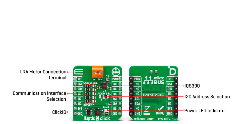
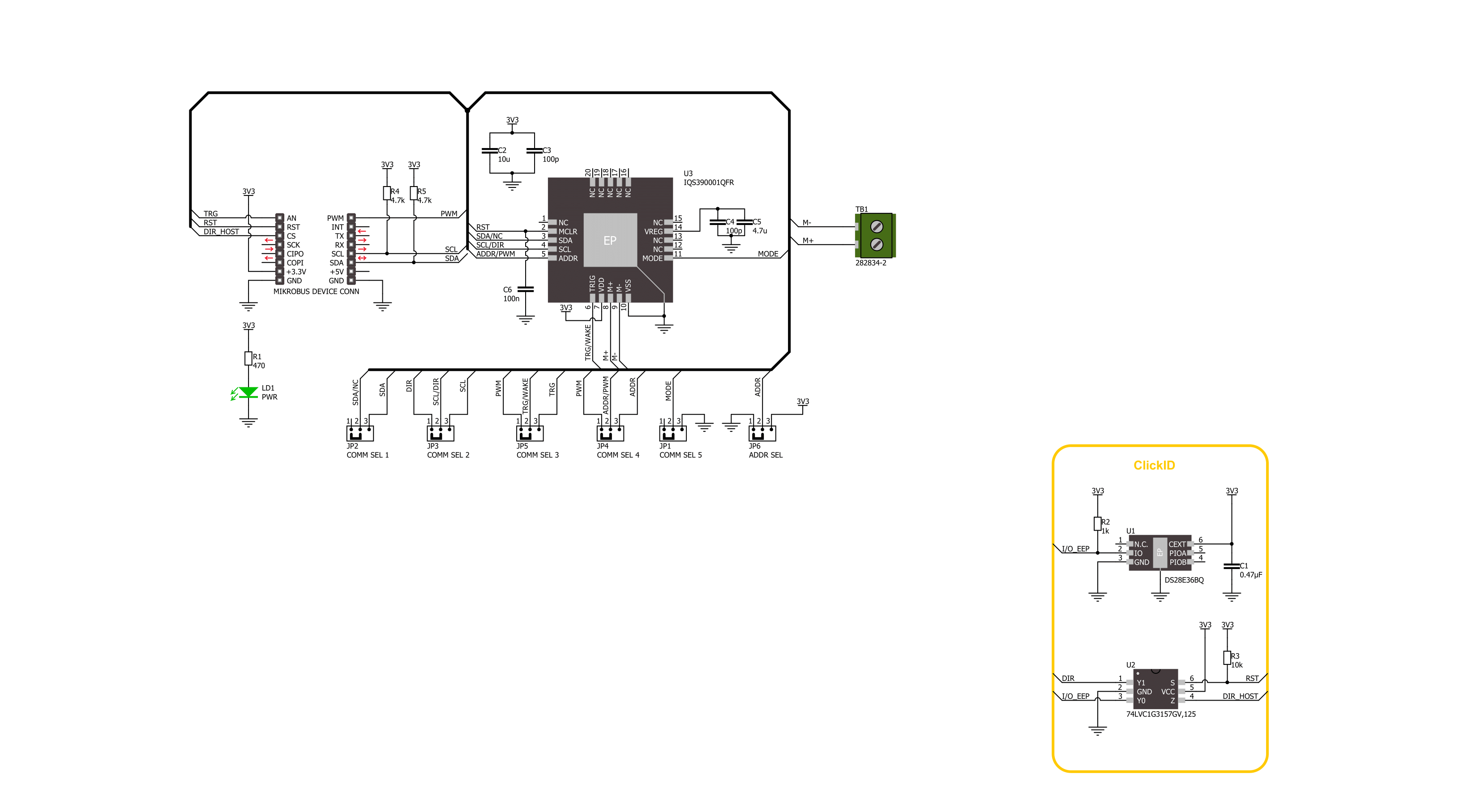
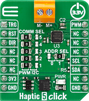
Haptic 5 Click is based on the IQS390 haptic driver IC from Azoteq, designed to provide high-performance haptic feedback using Linear Resonant Actuators (LRA). This board supports two operating modes— I2C and PWM— selectable via the COMM SEL jumpers. To ensure proper operation, all jumpers must be aligned to the same mode side. In I2C mode, the IQS390 employs a real-time closed-loop auto-resonance algorithm that dynamically tracks and matches the resonant frequency of the connected LRA motor, ensuring efficient and consistent vibration output. Haptic 5 Click is ideal for applications that require precise
and responsive tactile feedback, such as mouse wheel scrolling effects, trackpad interactions, doorbell notifications, and membrane keypads. The I2C interface supports communication speeds of up to Fast Mode Plus (1 MHz), with a selectable I2C address configured via the ADDR SEL jumper, enabling flexible integration into various systems. Additionally, the IQS390 includes a dedicated RST pin for hardware reset, and haptic pulses can be triggered either through I2C commands or externally via the TRG pin. In PWM mode, the board accepts an external Pulse Width Modulated signal along with a motor drive direction input via
the DIR pin. Both operating modes feature automatic power mode management, including an ultra-low power state to reduce energy consumption during inactivity. This Click board™ can be operated only with a 3.3V logic voltage level. The board must perform appropriate logic voltage level conversion before using MCUs with different logic levels. It also comes equipped with a library containing functions and example code that can be used as a reference for further development.
Features overview
Development board
Nucleo-64 with STM32F103RB MCU offers a cost-effective and adaptable platform for developers to explore new ideas and prototype their designs. This board harnesses the versatility of the STM32 microcontroller, enabling users to select the optimal balance of performance and power consumption for their projects. It accommodates the STM32 microcontroller in the LQFP64 package and includes essential components such as a user LED, which doubles as an ARDUINO® signal, alongside user and reset push-buttons, and a 32.768kHz crystal oscillator for precise timing operations. Designed with expansion and flexibility in mind, the Nucleo-64 board features an ARDUINO® Uno V3 expansion connector and ST morpho extension pin
headers, granting complete access to the STM32's I/Os for comprehensive project integration. Power supply options are adaptable, supporting ST-LINK USB VBUS or external power sources, ensuring adaptability in various development environments. The board also has an on-board ST-LINK debugger/programmer with USB re-enumeration capability, simplifying the programming and debugging process. Moreover, the board is designed to simplify advanced development with its external SMPS for efficient Vcore logic supply, support for USB Device full speed or USB SNK/UFP full speed, and built-in cryptographic features, enhancing both the power efficiency and security of projects. Additional connectivity is
provided through dedicated connectors for external SMPS experimentation, a USB connector for the ST-LINK, and a MIPI® debug connector, expanding the possibilities for hardware interfacing and experimentation. Developers will find extensive support through comprehensive free software libraries and examples, courtesy of the STM32Cube MCU Package. This, combined with compatibility with a wide array of Integrated Development Environments (IDEs), including IAR Embedded Workbench®, MDK-ARM, and STM32CubeIDE, ensures a smooth and efficient development experience, allowing users to fully leverage the capabilities of the Nucleo-64 board in their projects.

Microcontroller Overview
MCU Card / MCU

Architecture
ARM Cortex-M3
MCU Memory (KB)
128
Silicon Vendor
STMicroelectronics
Pin count
64
RAM (Bytes)
20480
You complete me!
Accessories
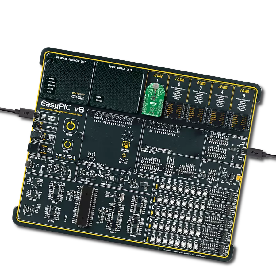
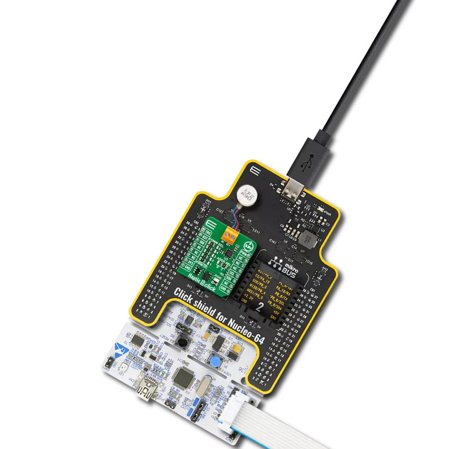
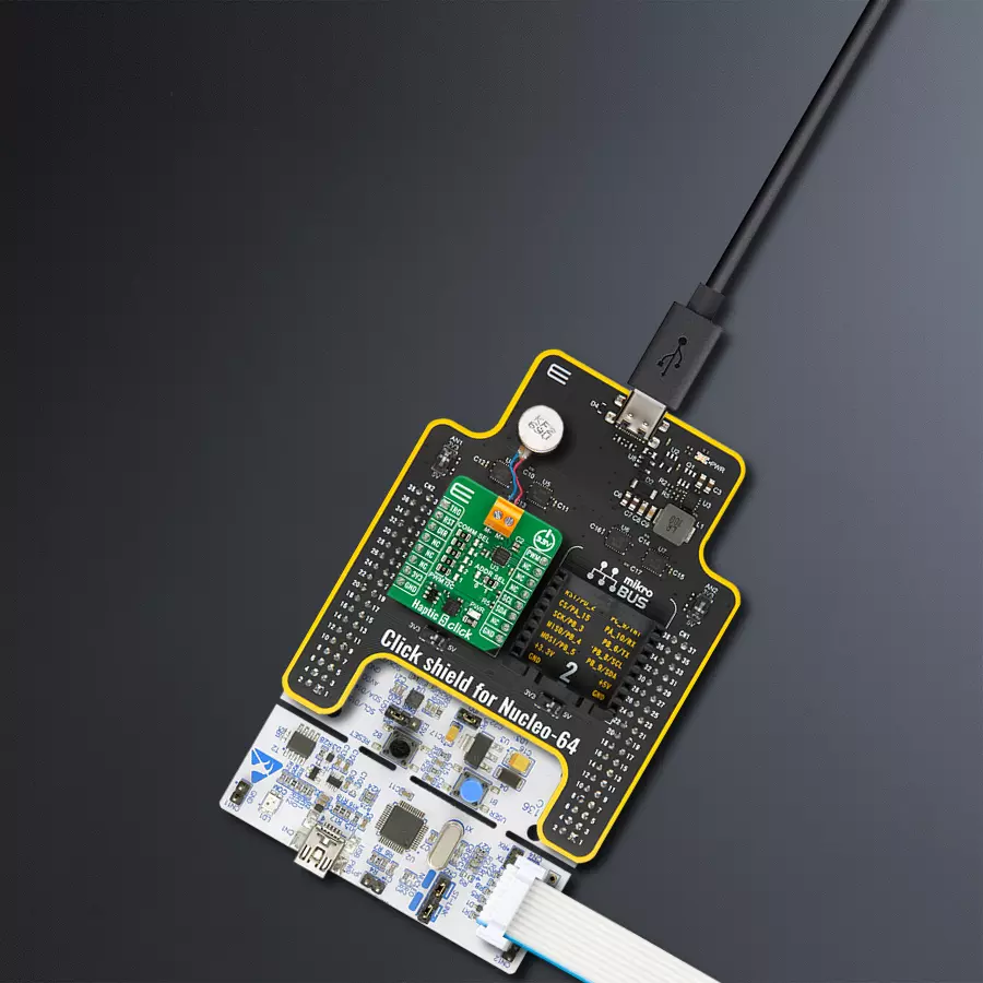
Click Shield for Nucleo-64 comes equipped with two proprietary mikroBUS™ sockets, allowing all the Click board™ devices to be interfaced with the STM32 Nucleo-64 board with no effort. This way, Mikroe allows its users to add any functionality from our ever-growing range of Click boards™, such as WiFi, GSM, GPS, Bluetooth, ZigBee, environmental sensors, LEDs, speech recognition, motor control, movement sensors, and many more. More than 1537 Click boards™, which can be stacked and integrated, are at your disposal. The STM32 Nucleo-64 boards are based on the microcontrollers in 64-pin packages, a 32-bit MCU with an ARM Cortex M4 processor operating at 84MHz, 512Kb Flash, and 96KB SRAM, divided into two regions where the top section represents the ST-Link/V2 debugger and programmer while the bottom section of the board is an actual development board. These boards are controlled and powered conveniently through a USB connection to program and efficiently debug the Nucleo-64 board out of the box, with an additional USB cable connected to the USB mini port on the board. Most of the STM32 microcontroller pins are brought to the IO pins on the left and right edge of the board, which are then connected to two existing mikroBUS™ sockets. This Click Shield also has several switches that perform functions such as selecting the logic levels of analog signals on mikroBUS™ sockets and selecting logic voltage levels of the mikroBUS™ sockets themselves. Besides, the user is offered the possibility of using any Click board™ with the help of existing bidirectional level-shifting voltage translators, regardless of whether the Click board™ operates at a 3.3V or 5V logic voltage level. Once you connect the STM32 Nucleo-64 board with our Click Shield for Nucleo-64, you can access hundreds of Click boards™, working with 3.3V or 5V logic voltage levels.

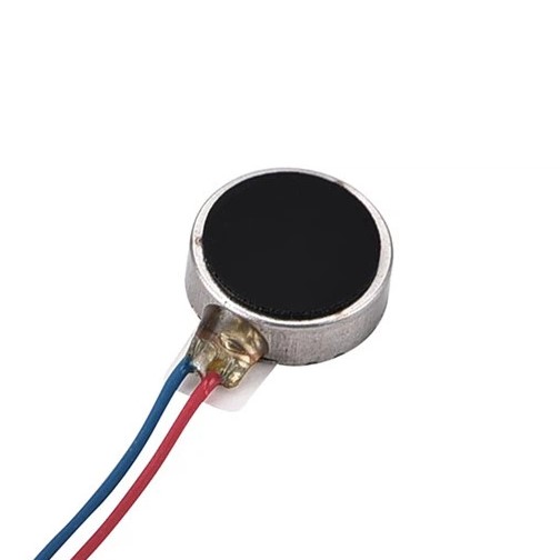
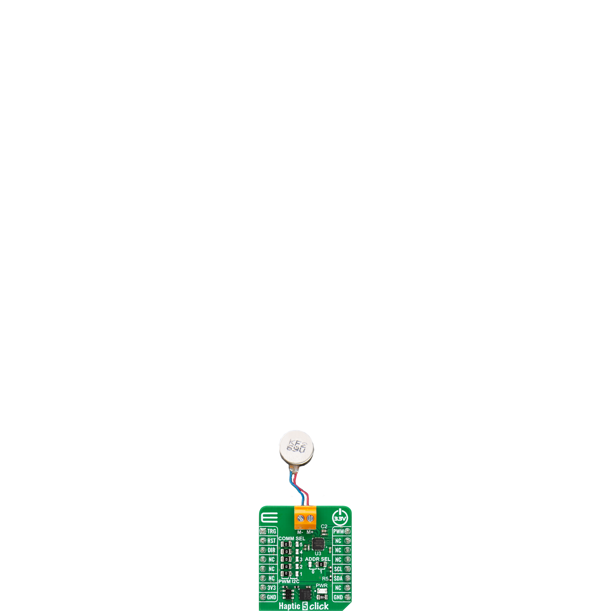
The LRA0825BC-0167F is a precision linear resonant actuator (LRA) designed for compact haptic feedback applications, featuring an 8mm diameter and 2.5mm thickness. Optimized for Z-axis vibration output, it operates at a resonant frequency of 240 ±10Hz, producing a minimum vibration acceleration of 0.7 Grms. With a rated voltage of 1.2 Vrms AC and a maximum current consumption of 90 mA, it ensures responsive performance with a rise time of up to 50 ms and a fall time of up to 80 ms. Its operating voltage range of 0.1 to 1.25 Vrms AC allows flexible control, making it ideal for wearable devices, handheld instruments, and other space-constrained designs requiring precise and efficient tactile feedback.
Used MCU Pins
mikroBUS™ mapper
Take a closer look
Click board™ Schematic
Step by step
Project assembly
Start by selecting your development board and Click board™. Begin with the Nucleo 64 with STM32F103RB MCU as your development board.


Track your results in real time
Application Output
1. Application Output - In Debug mode, the 'Application Output' window enables real-time data monitoring, offering direct insight into execution results. Ensure proper data display by configuring the environment correctly using the provided tutorial.

2. UART Terminal - Use the UART Terminal to monitor data transmission via a USB to UART converter, allowing direct communication between the Click board™ and your development system. Configure the baud rate and other serial settings according to your project's requirements to ensure proper functionality. For step-by-step setup instructions, refer to the provided tutorial.

3. Plot Output - The Plot feature offers a powerful way to visualize real-time sensor data, enabling trend analysis, debugging, and comparison of multiple data points. To set it up correctly, follow the provided tutorial, which includes a step-by-step example of using the Plot feature to display Click board™ readings. To use the Plot feature in your code, use the function: plot(*insert_graph_name*, variable_name);. This is a general format, and it is up to the user to replace 'insert_graph_name' with the actual graph name and 'variable_name' with the parameter to be displayed.

Software Support
Library Description
Haptic 5 Click demo application is developed using the NECTO Studio, ensuring compatibility with mikroSDK's open-source libraries and tools. Designed for plug-and-play implementation and testing, the demo is fully compatible with all development, starter, and mikromedia boards featuring a mikroBUS™ socket.
Example Description
This example demonstrates the control of the Haptic 5 Click board. In I2C mode, the example toggles the haptic trigger pin periodically to generate vibration pulses. In PWM mode, it gradually increases and decreases the output duty cycle to modulate the vibration intensity, while toggling the direction when the duty reaches 0%.
Key functions:
haptic5_cfg_setup- This function initializes Click configuration structure to initial values.haptic5_init- This function initializes all necessary pins and peripherals used for this Click board.haptic5_default_cfg- This function executes a default configuration of Haptic 5 Click board.haptic5_set_duty_cycle- This function sets the PWM duty cycle.haptic5_toggle_dir- This function toggles the state of the DIR pin.
Application Init
Initializes the logger and the Click board driver, and applies the default configuration.
Application Task
Depending on the selected communication interface (I2C or PWM), toggles the haptic trigger (I2C), or changes PWM duty cycle and direction (PWM).
Open Source
Code example
The complete application code and a ready-to-use project are available through the NECTO Studio Package Manager for direct installation in the NECTO Studio. The application code can also be found on the MIKROE GitHub account.
/*!
 * @file main.c
 * @brief Haptic 5 Click example
 *
 * # Description
 * This example demonstrates the control of the Haptic 5 Click board.
 * In I2C mode, the example toggles the haptic trigger pin periodically to generate vibration pulses.
 * In PWM mode, it gradually increases and decreases the output duty cycle to modulate the vibration intensity,
 * while toggling the direction when the duty reaches 0%.
 *
 * The demo application is composed of two sections :
 *
 * ## Application Init
 * Initializes the logger and the Click board driver, and applies the default configuration.
 *
 * ## Application Task
 * Depending on the selected communication interface (I2C or PWM), toggles the haptic trigger (I2C),
 * or changes PWM duty cycle and direction (PWM).
 *
 * @note
 * The mode is selected via the @b HAPTIC5_DEFAULT_COM macro. Ensure proper configuration and wiring
 * based on the selected mode before running the example.
 *
 * @author Stefan Filipovic
 *
 */

#include "board.h"
#include "log.h"
#include "haptic5.h"

static haptic5_t haptic5;
static log_t logger;

void application_init ( void )
{
    log_cfg_t log_cfg;  /**< Logger config object. */
    haptic5_cfg_t haptic5_cfg;  /**< Click config object. */

    /**
     * Logger initialization.
     * Default baud rate: 115200
     * Default log level: LOG_LEVEL_DEBUG
     * @note If USB_UART_RX and USB_UART_TX
     * are defined as HAL_PIN_NC, you will
     * need to define them manually for log to work.
     * See @b LOG_MAP_USB_UART macro definition for detailed explanation.
     */
    LOG_MAP_USB_UART( log_cfg );
    log_init( &logger, &log_cfg );
    log_info( &logger, " Application Init " );

    // Click initialization.
    haptic5_cfg_setup( &haptic5_cfg );
    HAPTIC5_MAP_MIKROBUS( haptic5_cfg, MIKROBUS_1 );
    if ( PWM_ERROR == haptic5_init( &haptic5, &haptic5_cfg ) )
    {
        log_error( &logger, " Communication init." );
        for ( ; ; );
    }

    if ( HAPTIC5_ERROR == haptic5_default_cfg ( &haptic5 ) )
    {
        log_error( &logger, " Default configuration." );
        for ( ; ; );
    }

    log_info( &logger, " Application Task " );
}

void application_task ( void )
{
#if ( HAPTIC5_DEFAULT_COM == HAPTIC5_COM_I2C )
    log_printf( &logger, " Haptic state: Active\r\n\n" );
    haptic5_set_trg_high ( &haptic5 );
    Delay_ms ( 1000 );
    log_printf( &logger, " Haptic state: Idle\r\n\n" );
    haptic5_set_trg_low ( &haptic5 );
    Delay_ms ( 1000 );
#else
    static int8_t duty_cnt = 1;
    static int8_t duty_inc = 1;
    float duty = duty_cnt / 10.0;

    haptic5_set_duty_cycle ( &haptic5, duty );
    log_printf( &logger, "> Duty: %d%%\r\n", ( uint16_t )( duty_cnt * 10 ) );

    Delay_ms ( 500 );

    if ( 10 == duty_cnt )
    {
        duty_inc = -1;
    }
    else if ( 0 == duty_cnt )
    {
        duty_inc = 1;
        haptic5_toggle_dir ( &haptic5 );
    }
    duty_cnt += duty_inc;
#endif
}

int main ( void )
{
    /* Do not remove this line or clock might not be set correctly. */
    #ifdef PREINIT_SUPPORTED
    preinit();
    #endif

    application_init( );

    for ( ; ; )
    {
        application_task( );
    }

    return 0;
}

// ------------------------------------------------------------------------ END
Additional Support
Resources
Category:Haptic