Achieve low-power LTE-M and NB-IoT connectivity with LEXI-R520 and PIC32MX470F512H
Multi-band LTE-M/NB-IoT solution integrating cellular modem and A-GPS technology
Published Mar 27, 2025
Click board™
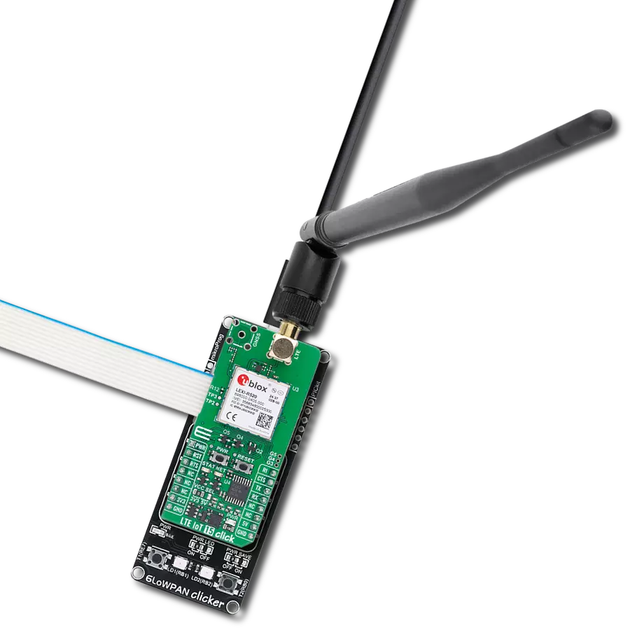
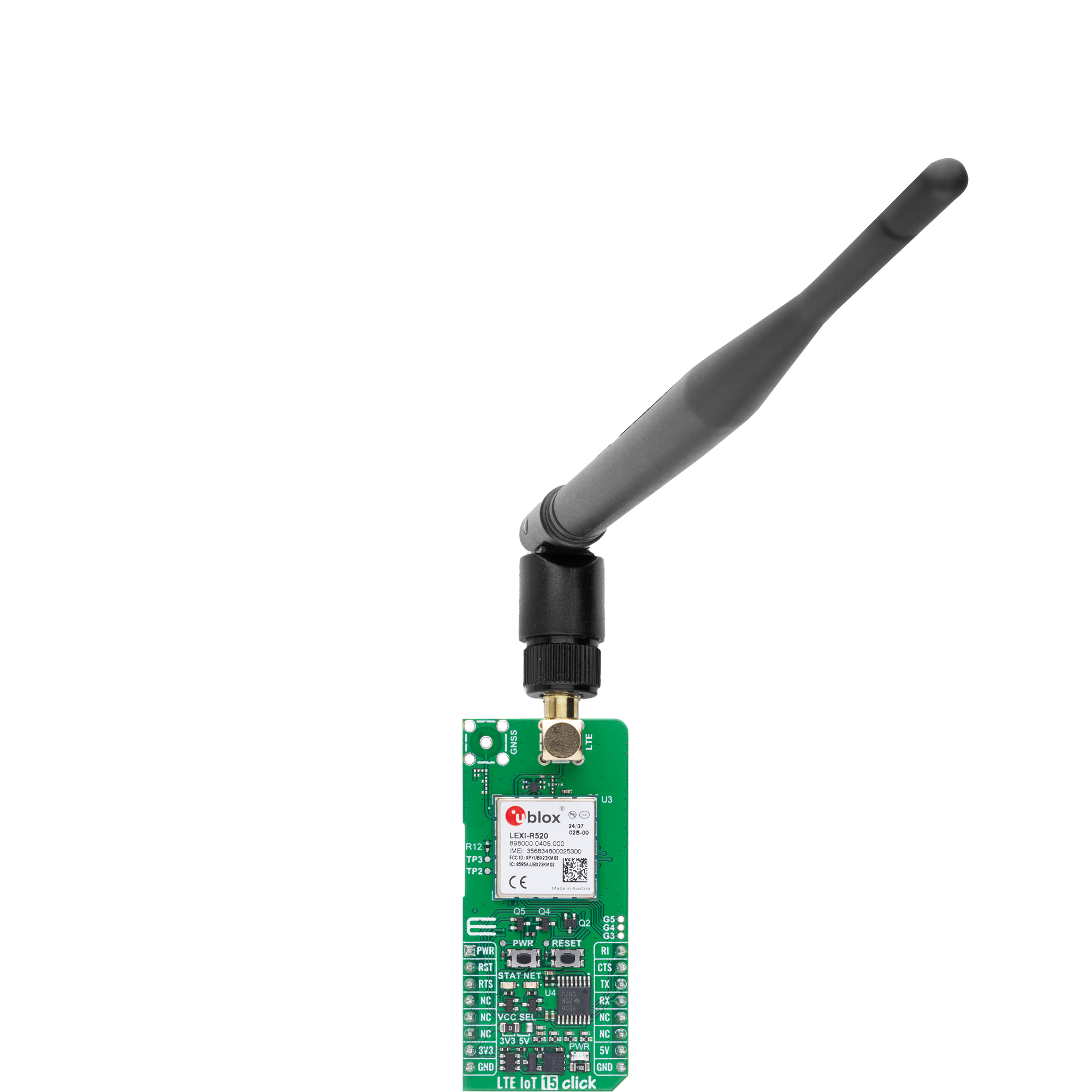
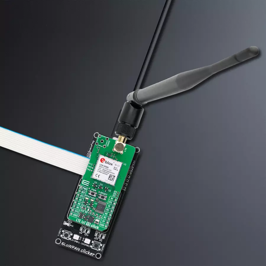
LTE IoT 15 Click
Dev. board
6LoWPAN clicker
Compiler
NECTO Studio
MCU
PIC32MX470F512H
Low-power LTE-M and NB-IoT connectivity for global IoT applications for asset tracking, smart metering, and remote monitoring
A
A
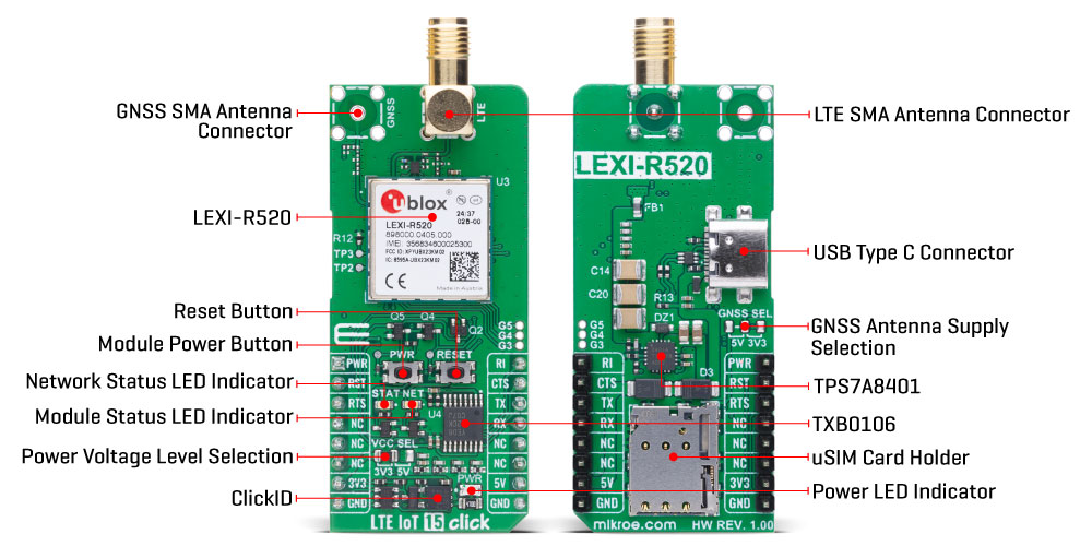
Hardware Overview
How does it work?
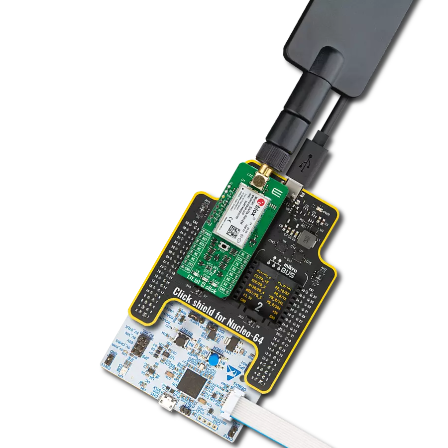
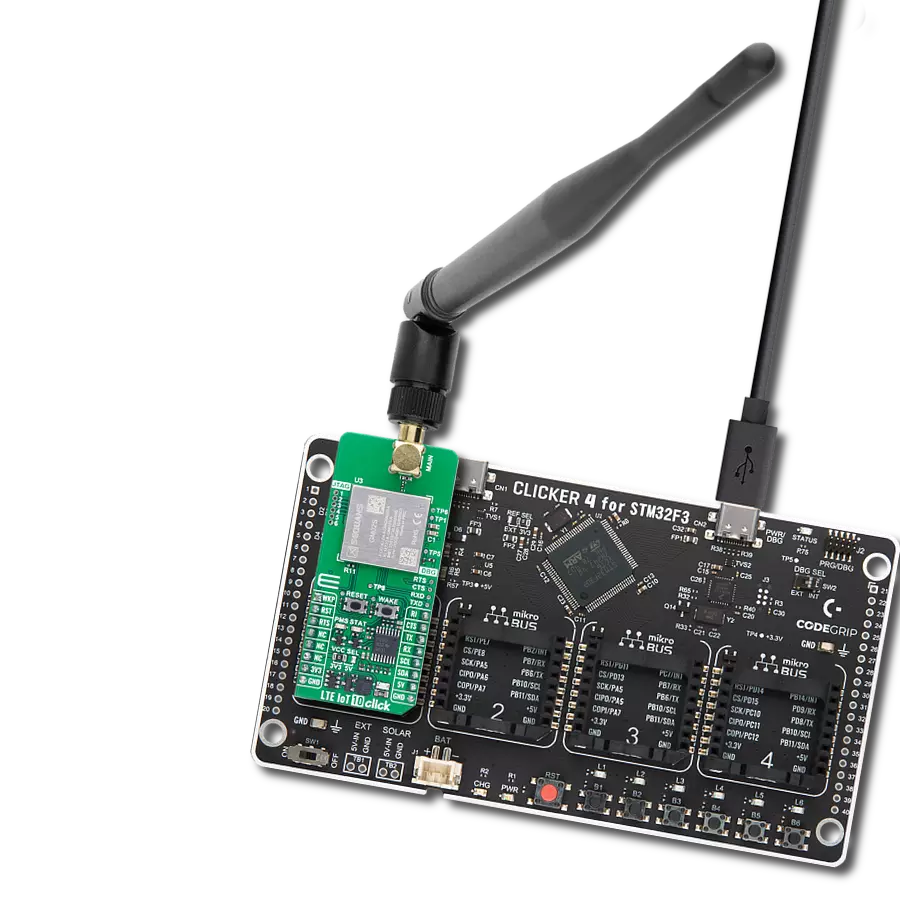
LTE IoT 15 Click is based on the LEXI-R520, a multi-band LTE-M/NB-IoT module from Trasna. Built on the UBX-R52 chipset, this module combines cellular connectivity with assisted GPS, offering data transmission and location tracking. Optimized for ultra-low power consumption, the LEXI-R520 supports deep-sleep modes like PSM and eDRX, making it ideal for battery-powered IoT applications. Its software-based multi-band configurability ensures global network compatibility, while 3GPP Release 14 features enable extended coverage, even in basements and underground areas when using NB2. A key advantage is its support for over-the-air firmware updates via Trasna’s uFOTA system, using the LwM2M protocol for efficient and lightweight updates. The module operates on multiple LTE bands (1/2/3/4/5/8/12/13/18/19/20/25/26/28/66/71/85), with a transmission power of +23dBm and data rates of up to 1200 kbit/s (uplink) and 588 kbit/s (downlink). Designed for compact IoT devices, this board is perfect for asset tracking, wearables, smart metering, remote monitoring, and connected healthcare. With an integrated IP stack and multiple interface options, it supports low-to-medium data throughput while ensuring long battery life. Communication between the LEXI-R520 and the host MCU is made through a UART interface, using
standard UART RX and TX pins and hardware flow control pins (CTS/RTS/RI - Clear to Send/Ready to Send/Ring Indicator) for efficient data transfer. The module defaults to a communication speed of 115200bps, allowing for seamless data exchange over AT commands. This Click board™ also includes a USB Type C connector for both power and data transfer, compliant with the USB 2.0 specification, available for diagnostic purpose only. The LTE IoT 15 Click includes several additional functionalities that enhance its usability and control. The PWR button allows users to easily power the module ON or OFF, while the RESET button provides a quick way to reset the module. These functions can also be controlled digitally via the mikroBUS™ pins PWR and RST, offering greater flexibility. Moreover, this board also has dedicated test points (TP2/TP3) for easier debugging and testing, one unsoldered header with three configurable GPIO pins from LEXI-R520, and two visual indicators to provide real-time status updates. The first red NET LED indicates the current network status of the module like when the device has successfully registered on the network, has not yet registered to a network, or signals when data transmission occurs. When the LED is completely OFF, it indicates that the device is either powered OFF or in Power Saving Mode. The
second yellow STAT LED indicates the module's status; power-off or deep-sleep mode versus idle, active or connected mode. The board features an SMA connector for an LTE antenna, such as the GSM/GPRS antenna offered by MIKROE, ensuring efficient connectivity options. However, please note that GNSS functionality is not currently supported on this Click board™, and as a result, GNSS-related components are not soldered. While the board includes a GNSS ANT jumper at the back, allowing the selection of either 3.3V or 5V for an optional GNSS antenna, this feature remains non-functional due to the absence of GNSS support. The board also has a micro SIM card holder that supports both 1.8V and 3.0V uSIM cards, allowing users to select the most appropriate service provider for their particular use case. This Click board™ can operate with both 3.3V and 5V logic voltage levels selected via the VCC SEL jumper. Since the LEXI-R520 module operates at 3.8V, a logic-level translator, the TXB0106, is also used for proper operation and an accurate signal-level translation. This way, both 3.3V and 5V capable MCUs can use the communication lines properly. Also, this Click board™ comes equipped with a library containing easy-to-use functions and an example code that can be used as a reference for further development.
Features overview
Development board
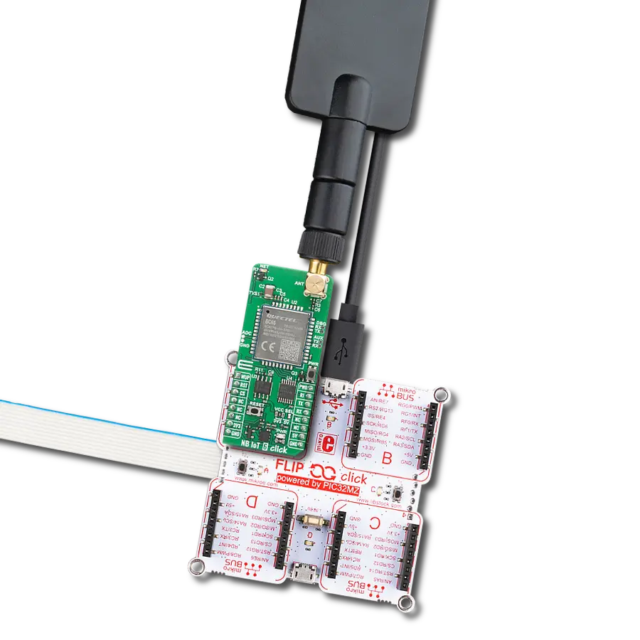
6LoWPAN Clicker is a compact starter development board that brings the flexibility of add-on Click boards™ to your favorite microcontroller, making it a perfect starter kit for implementing your ideas. It comes with an onboard 32-bit PIC microcontroller, the PIC32MX470F512H from Microchip, a USB connector, LED indicators, buttons, a mikroProg connector, and a header for interfacing with external electronics. Along with this microcontroller, the board also contains a 2.4GHz ISM band transceiver, allowing you to add wireless communication to your target application. Its compact design provides a fluid and immersive working experience, allowing access anywhere
and under any circumstances. Each part of the 6LoWPAN Clicker development kit contains the components necessary for the most efficient operation of the same board. In addition to the possibility of choosing the 6LoWPAN Clicker programming method, using USB HID mikroBootloader, or through an external mikroProg connector for PIC, dsPIC, or PIC32 programmer, the Clicker board also includes a clean and regulated power supply module for the development kit. The USB Micro-B connection can provide up to 500mA of current for the Clicker board, which is more than enough to operate all onboard and additional modules, or it can power
over two standard AA batteries. All communication methods that mikroBUS™ itself supports are on this board, including the well-established mikroBUS™ socket, reset button, and several buttons and LED indicators. 6LoWPAN Clicker is an integral part of the Mikroe ecosystem, allowing you to create a new application in minutes. Natively supported by Mikroe software tools, it covers many aspects of prototyping thanks to a considerable number of different Click boards™ (over a thousand boards), the number of which is growing every day.

Microcontroller Overview
MCU Card / MCU

Architecture
PIC32
MCU Memory (KB)
512
Silicon Vendor
Microchip
Pin count
64
RAM (Bytes)
131072
You complete me!
Accessories
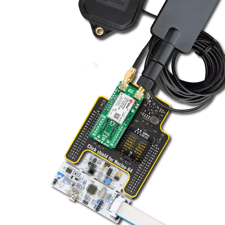
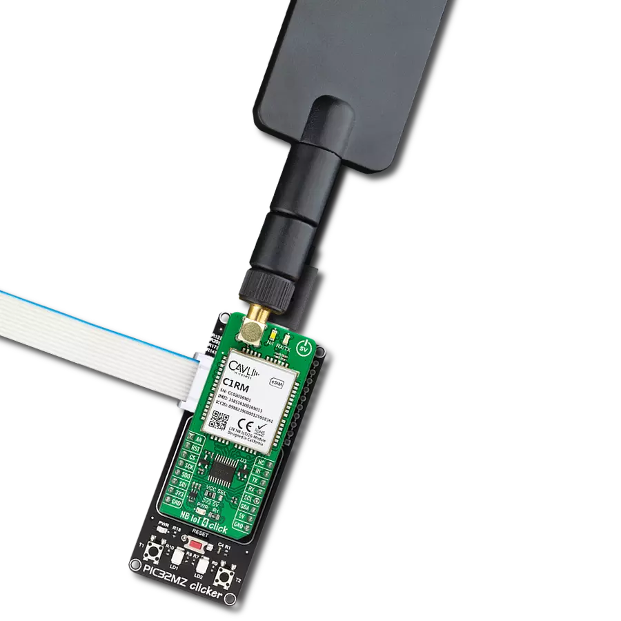
This multiband LTE Rubber Antenna with adjustable angle is an excellent choice for all 3G/4G LTE-based click boards from our offer, as well as other devices that require excellent throughput on all major cellular bands worldwide. The antenna has an SMA male connector, which allows it to be mounted directly on the Click board™ or the female SMA module connector. The antenna position can be adjusted in 45⁰ increments (0⁰/45⁰/90⁰).

Used MCU Pins
mikroBUS™ mapper
Take a closer look
Click board™ Schematic

Step by step
Project assembly

Start by selecting your development board and Click board™. Begin with the 6LoWPAN clicker as your development board.


Software Support
Library Description
LTE IoT 15 Click demo application is developed using the NECTO Studio, ensuring compatibility with mikroSDK's open-source libraries and tools. Designed for plug-and-play implementation and testing, the demo is fully compatible with all development, starter, and mikromedia boards featuring a mikroBUS™ socket.
Example Description
Application example shows device capability of connecting to the network and sending SMS or TCP/UDP messages using standard "AT" commands.
Key functions:
lteiot15_cfg_setup- This function initializes Click configuration structure to initial values.lteiot15_init- This function initializes all necessary pins and peripherals used for this Click board.lteiot15_set_sim_apn- This function sets APN for sim card.lteiot15_send_sms_text- This function sends text message to a phone number.lteiot15_cmd_set- This function sets a value to a specified command of the Click module.
Application Init
Initializes the driver and logger.
Application Task
Application task is split in few stages:
LTEIOT15_POWER_UP:Powers up the device, performs a device factory reset and reads system information.LTEIOT15_CONFIG_CONNECTION:Sets configuration to device to be able to connect to the network.LTEIOT15_CHECK_CONNECTION:Waits for the network registration indicated via CEREG command and then checks the signal quality report.LTEIOT15_CONFIG_EXAMPLE:Configures device for the selected example.LTEIOT15_EXAMPLE:Depending on the selected demo example, it sends an SMS message (in PDU or TXT mode) or TCP/UDP message. By default, the TCP/UDP example is selected.
Open Source
Code example
The complete application code and a ready-to-use project are available through the NECTO Studio Package Manager for direct installation in the NECTO Studio. The application code can also be found on the MIKROE GitHub account.
/*!
* @file main.c
* @brief LTE IoT 15 Click Example.
*
* # Description
* Application example shows device capability of connecting to the network and
* sending SMS or TCP/UDP messages using standard "AT" commands.
*
* The demo application is composed of two sections :
*
* ## Application Init
* Initializes the driver and logger.
*
* ## Application Task
* Application task is split in few stages:
* - LTEIOT15_POWER_UP:
* Powers up the device, performs a device factory reset and reads system information.
*
* - LTEIOT15_CONFIG_CONNECTION:
* Sets configuration to device to be able to connect to the network.
*
* - LTEIOT15_CHECK_CONNECTION:
* Waits for the network registration indicated via CEREG command and then checks the signal quality report.
*
* - LTEIOT15_CONFIG_EXAMPLE:
* Configures device for the selected example.
*
* - LTEIOT15_EXAMPLE:
* Depending on the selected demo example, it sends an SMS message (in PDU or TXT mode) or TCP/UDP message.
*
* By default, the TCP/UDP example is selected.
*
* ## Additional Function
* - static void lteiot15_clear_app_buf ( void )
* - static void lteiot15_log_app_buf ( void )
* - static err_t lteiot15_process ( lteiot15_t *ctx )
* - static err_t lteiot15_read_response ( lteiot15_t *ctx, uint8_t *rsp )
* - static err_t lteiot15_power_up ( lteiot15_t *ctx )
* - static err_t lteiot15_config_connection ( lteiot15_t *ctx )
* - static err_t lteiot15_check_connection ( lteiot15_t *ctx )
* - static err_t lteiot15_config_example ( lteiot15_t *ctx )
* - static err_t lteiot15_example ( lteiot15_t *ctx )
*
* @note
* In order for the examples to work, user needs to set the APN and SMSC (SMS PDU mode only)
* of entered SIM card as well as the phone number (SMS mode only) to which he wants to send an SMS.
* Enter valid values for the following macros: SIM_APN, SIM_SMSC and PHONE_NUMBER.
* Example:
SIM_APN "internet"
SIM_SMSC "+381610401"
PHONE_NUMBER "+381659999999"
*
* @author Stefan Filipovic
*
*/
#include "board.h"
#include "log.h"
#include "lteiot15.h"
#include "generic_pointer.h"
#include "conversions.h"
// Example selection macros
#define EXAMPLE_TCP_UDP 0 // Example of sending messages to a TCP/UDP echo server
#define EXAMPLE_SMS 1 // Example of sending SMS to a phone number
#define DEMO_EXAMPLE EXAMPLE_TCP_UDP // Example selection macro
// SIM APN config
#define SIM_APN "internet" // Set valid SIM APN
// SMS example parameters
#define SIM_SMSC "" // Set valid SMS Service Center Address - only in SMS PDU mode
#define PHONE_NUMBER "" // Set Phone number to message
#define SMS_MODE "1" // SMS mode: "0" - PDU, "1" - TXT
// TCP/UDP example parameters
#define REMOTE_IP "77.46.162.162" // TCP/UDP echo server IP address
#define REMOTE_PORT "51111" // TCP/UDP echo server port
// Message content
#define MESSAGE_CONTENT "LTE IoT 15 Click board - demo example."
// Application buffer size
#define APP_BUFFER_SIZE 256
#define PROCESS_BUFFER_SIZE 256
/**
* @brief Example states.
* @details Predefined enum values for application example state.
*/
typedef enum
{
LTEIOT15_POWER_UP = 1,
LTEIOT15_CONFIG_CONNECTION,
LTEIOT15_CHECK_CONNECTION,
LTEIOT15_CONFIG_EXAMPLE,
LTEIOT15_EXAMPLE
} lteiot15_app_state_t;
/**
* @brief Application example variables.
* @details Variables used in application example.
*/
static uint8_t app_buf[ APP_BUFFER_SIZE ] = { 0 };
static int32_t app_buf_len = 0;
static lteiot15_app_state_t app_state = LTEIOT15_POWER_UP;
static lteiot15_t lteiot15;
static log_t logger;
/**
* @brief LTE IoT 15 clearing application buffer.
* @details This function clears memory of application buffer and reset its length.
* @note None.
*/
static void lteiot15_clear_app_buf ( void );
/**
* @brief LTE IoT 15 log application buffer.
* @details This function logs data from application buffer to USB UART.
* @note None.
*/
static void lteiot15_log_app_buf ( void );
/**
* @brief LTE IoT 15 data reading function.
* @details This function reads data from device and concatenates data to application buffer.
* @param[in] ctx : Click context object.
* See #lteiot15_t object definition for detailed explanation.
* @return @li @c 0 - Read some data.
* @li @c -1 - Nothing is read.
* See #err_t definition for detailed explanation.
* @note None.
*/
static err_t lteiot15_process ( lteiot15_t *ctx );
/**
* @brief LTE IoT 15 read response function.
* @details This function waits for a response message, reads and displays it on the USB UART.
* @param[in] ctx : Click context object.
* See #lteiot15_t object definition for detailed explanation.
* @param[in] rsp Expected response.
* @return @li @c 0 - OK response.
* @li @c -2 - Timeout error.
* @li @c -3 - Command error.
* See #err_t definition for detailed explanation.
* @note None.
*/
static err_t lteiot15_read_response ( lteiot15_t *ctx, uint8_t *rsp );
/**
* @brief LTE IoT 15 power up function.
* @details This function powers up the device, performs a factory reset and reads system information.
* @param[in] ctx : Click context object.
* See #lteiot15_t object definition for detailed explanation.
* @return @li @c 0 - OK.
* @li @c != 0 - Read response error.
* See #err_t definition for detailed explanation.
* @note None.
*/
static err_t lteiot15_power_up ( lteiot15_t *ctx );
/**
* @brief LTE IoT 15 config connection function.
* @details This function configures and enables connection to the specified network.
* @param[in] ctx : Click context object.
* See #lteiot15_t object definition for detailed explanation.
* @return @li @c 0 - OK.
* @li @c != 0 - Read response error.
* See #err_t definition for detailed explanation.
* @note None.
*/
static err_t lteiot15_config_connection ( lteiot15_t *ctx );
/**
* @brief LTE IoT 15 check connection function.
* @details This function checks the connection to network.
* @param[in] ctx : Click context object.
* See #lteiot15_t object definition for detailed explanation.
* @return @li @c 0 - OK.
* @li @c != 0 - Read response error.
* See #err_t definition for detailed explanation.
* @note None.
*/
static err_t lteiot15_check_connection ( lteiot15_t *ctx );
/**
* @brief LTE IoT 15 config example function.
* @details This function configures device for the selected example.
* @param[in] ctx : Click context object.
* See #lteiot15_t object definition for detailed explanation.
* @return @li @c 0 - OK.
* @li @c != 0 - Read response error.
* See #err_t definition for detailed explanation.
* @note None.
*/
static err_t lteiot15_config_example ( lteiot15_t *ctx );
/**
* @brief LTE IoT 15 example function.
* @details This function executes SMS or TCP/UDP depending on the DEMO_EXAMPLE macro.
* @param[in] ctx : Click context object.
* See #lteiot15_t object definition for detailed explanation.
* @return @li @c 0 - OK.
* @li @c != 0 - Read response error.
* See #err_t definition for detailed explanation.
* @note None.
*/
static err_t lteiot15_example ( lteiot15_t *ctx );
void application_init ( void )
{
log_cfg_t log_cfg; /**< Logger config object. */
lteiot15_cfg_t lteiot15_cfg; /**< Click config object. */
/**
* Logger initialization.
* Default baud rate: 115200
* Default log level: LOG_LEVEL_DEBUG
* @note If USB_UART_RX and USB_UART_TX
* are defined as HAL_PIN_NC, you will
* need to define them manually for log to work.
* See @b LOG_MAP_USB_UART macro definition for detailed explanation.
*/
LOG_MAP_USB_UART( log_cfg );
log_init( &logger, &log_cfg );
log_info( &logger, " Application Init " );
// Click initialization.
lteiot15_cfg_setup( <eiot15_cfg );
LTEIOT15_MAP_MIKROBUS( lteiot15_cfg, MIKROBUS_1 );
if ( UART_ERROR == lteiot15_init( <eiot15, <eiot15_cfg ) )
{
log_error( &logger, " Communication init." );
for ( ; ; );
}
log_info( &logger, " Application Task " );
app_state = LTEIOT15_POWER_UP;
log_printf( &logger, ">>> APP STATE - POWER UP <<<\r\n\n" );
}
void application_task ( void )
{
switch ( app_state )
{
case LTEIOT15_POWER_UP:
{
if ( LTEIOT15_OK == lteiot15_power_up( <eiot15 ) )
{
app_state = LTEIOT15_CONFIG_CONNECTION;
log_printf( &logger, ">>> APP STATE - CONFIG CONNECTION <<<\r\n\n" );
}
break;
}
case LTEIOT15_CONFIG_CONNECTION:
{
if ( LTEIOT15_OK == lteiot15_config_connection( <eiot15 ) )
{
app_state = LTEIOT15_CHECK_CONNECTION;
log_printf( &logger, ">>> APP STATE - CHECK CONNECTION <<<\r\n\n" );
}
break;
}
case LTEIOT15_CHECK_CONNECTION:
{
if ( LTEIOT15_OK == lteiot15_check_connection( <eiot15 ) )
{
app_state = LTEIOT15_CONFIG_EXAMPLE;
log_printf( &logger, ">>> APP STATE - CONFIG EXAMPLE <<<\r\n\n" );
}
break;
}
case LTEIOT15_CONFIG_EXAMPLE:
{
if ( LTEIOT15_OK == lteiot15_config_example( <eiot15 ) )
{
app_state = LTEIOT15_EXAMPLE;
log_printf( &logger, ">>> APP STATE - EXAMPLE <<<\r\n\n" );
}
break;
}
case LTEIOT15_EXAMPLE:
{
lteiot15_example( <eiot15 );
break;
}
default:
{
log_error( &logger, " APP STATE." );
break;
}
}
}
int main ( void )
{
/* Do not remove this line or clock might not be set correctly. */
#ifdef PREINIT_SUPPORTED
preinit();
#endif
application_init( );
for ( ; ; )
{
application_task( );
}
return 0;
}
static void lteiot15_clear_app_buf ( void )
{
memset( app_buf, 0, app_buf_len );
app_buf_len = 0;
}
static void lteiot15_log_app_buf ( void )
{
for ( int32_t buf_cnt = 0; buf_cnt < app_buf_len; buf_cnt++ )
{
log_printf( &logger, "%c", app_buf[ buf_cnt ] );
}
}
static err_t lteiot15_process ( lteiot15_t *ctx )
{
uint8_t rx_buf[ PROCESS_BUFFER_SIZE ] = { 0 };
int32_t overflow_bytes = 0;
int32_t rx_cnt = 0;
int32_t rx_size = lteiot15_generic_read( ctx, rx_buf, PROCESS_BUFFER_SIZE );
if ( ( rx_size > 0 ) && ( rx_size <= APP_BUFFER_SIZE ) )
{
if ( ( app_buf_len + rx_size ) > APP_BUFFER_SIZE )
{
overflow_bytes = ( app_buf_len + rx_size ) - APP_BUFFER_SIZE;
app_buf_len = APP_BUFFER_SIZE - rx_size;
memmove ( app_buf, &app_buf[ overflow_bytes ], app_buf_len );
memset ( &app_buf[ app_buf_len ], 0, overflow_bytes );
}
for ( rx_cnt = 0; rx_cnt < rx_size; rx_cnt++ )
{
if ( rx_buf[ rx_cnt ] )
{
app_buf[ app_buf_len++ ] = rx_buf[ rx_cnt ];
}
}
return LTEIOT15_OK;
}
return LTEIOT15_ERROR;
}
static err_t lteiot15_read_response ( lteiot15_t *ctx, uint8_t *rsp )
{
#define READ_RESPONSE_TIMEOUT_MS 120000
uint32_t timeout_cnt = 0;
lteiot15_clear_app_buf ( );
lteiot15_process( ctx );
while ( ( 0 == strstr( app_buf, rsp ) ) &&
( 0 == strstr( app_buf, LTEIOT15_RSP_ERROR ) ) )
{
lteiot15_process( ctx );
if ( timeout_cnt++ > READ_RESPONSE_TIMEOUT_MS )
{
lteiot15_log_app_buf( );
lteiot15_clear_app_buf( );
log_error( &logger, " Timeout!" );
return LTEIOT15_ERROR_TIMEOUT;
}
Delay_ms( 1 );
}
Delay_ms ( 200 );
lteiot15_process( ctx );
lteiot15_log_app_buf( );
if ( strstr( app_buf, rsp ) )
{
log_printf( &logger, "--------------------------------\r\n" );
return LTEIOT15_OK;
}
return LTEIOT15_ERROR_CMD;
}
static err_t lteiot15_power_up ( lteiot15_t *ctx )
{
err_t error_flag = LTEIOT15_OK;
uint8_t power_state = LTEIOT15_POWER_STATE_OFF;
for ( ; ; )
{
lteiot15_process( ctx );
lteiot15_log_app_buf ( );
lteiot15_clear_app_buf ( );
// Wake up UART interface
lteiot15_cmd_run( ctx, LTEIOT15_CMD_AT );
log_printf( &logger, ">>> Check communication.\r\n" );
lteiot15_cmd_run( ctx, LTEIOT15_CMD_AT );
if ( ( ( LTEIOT15_OK == lteiot15_process( ctx ) ) && strstr( app_buf, LTEIOT15_RSP_OK ) ) )
{
power_state = LTEIOT15_POWER_STATE_ON;
break;
}
else if ( LTEIOT15_POWER_STATE_OFF == power_state )
{
power_state = LTEIOT15_POWER_STATE_ON;
log_printf( &logger, ">>> Power up device.\r\n" );
lteiot15_set_power_state ( ctx, LTEIOT15_POWER_STATE_ON );
}
else if ( LTEIOT15_POWER_STATE_ON == power_state )
{
power_state = LTEIOT15_POWER_STATE_OFF;
log_printf( &logger, ">>> Power down device.\r\n" );
lteiot15_set_power_state ( ctx, LTEIOT15_POWER_STATE_OFF );
}
}
lteiot15_cmd_run( ctx, LTEIOT15_CMD_AT );
error_flag |= lteiot15_read_response( ctx, LTEIOT15_RSP_OK );
log_printf( &logger, ">>> Factory reset.\r\n" );
lteiot15_cmd_run( ctx, LTEIOT15_CMD_FACTORY_RESET );
error_flag |= lteiot15_read_response( ctx, LTEIOT15_RSP_OK );
log_printf( &logger, ">>> Get device software version ID.\r\n" );
lteiot15_cmd_run( ctx, LTEIOT15_CMD_GET_SW_VERSION );
error_flag |= lteiot15_read_response( ctx, LTEIOT15_RSP_OK );
log_printf( &logger, ">>> Get device serial number.\r\n" );
lteiot15_cmd_run( ctx, LTEIOT15_CMD_GET_SERIAL_NUM );
error_flag |= lteiot15_read_response( ctx, LTEIOT15_RSP_OK );
return error_flag;
}
static err_t lteiot15_config_connection ( lteiot15_t *ctx )
{
err_t error_flag = LTEIOT15_OK;
#if ( ( DEMO_EXAMPLE == EXAMPLE_TCP_UDP ) || ( DEMO_EXAMPLE == EXAMPLE_SMS ) )
log_printf( &logger, ">>> Configure network status LED.\r\n" );
#define NETWORK_STATUS_LED "14,2"
lteiot15_cmd_set( ctx, LTEIOT15_CMD_GPIO_CONFIG, NETWORK_STATUS_LED );
error_flag |= lteiot15_read_response( ctx, LTEIOT15_RSP_OK );
log_printf( &logger, ">>> Configure module status LED.\r\n" );
#define MODULE_STATUS_LED "15,10"
lteiot15_cmd_set( ctx, LTEIOT15_CMD_GPIO_CONFIG, MODULE_STATUS_LED );
error_flag |= lteiot15_read_response( ctx, LTEIOT15_RSP_OK );
log_printf( &logger, ">>> Deregister from network.\r\n" );
#define DEREGISTER_FROM_NETWORK "2"
lteiot15_cmd_set( ctx, LTEIOT15_CMD_OPERATOR_SELECTION, DEREGISTER_FROM_NETWORK );
error_flag |= lteiot15_read_response( ctx, LTEIOT15_RSP_OK );
log_printf( &logger, ">>> Set SIM APN.\r\n" );
lteiot15_set_sim_apn( <eiot15, SIM_APN );
error_flag |= lteiot15_read_response( ctx, LTEIOT15_RSP_OK );
log_printf( &logger, ">>> Enable full functionality.\r\n" );
#define FULL_FUNCTIONALITY "1"
lteiot15_cmd_set( ctx, LTEIOT15_CMD_SET_MODULE_FUNCTIONALITY, FULL_FUNCTIONALITY );
error_flag |= lteiot15_read_response( ctx, LTEIOT15_RSP_OK );
log_printf( &logger, ">>> Enable network registration.\r\n" );
#define ENABLE_REG "2"
lteiot15_cmd_set( ctx, LTEIOT15_CMD_EPS_NETWORK_REGISTRATION, ENABLE_REG );
error_flag |= lteiot15_read_response( ctx, LTEIOT15_RSP_OK );
log_printf( &logger, ">>> Set automatic registration.\r\n" );
#define AUTOMATIC_REGISTRATION "0"
lteiot15_cmd_set( ctx, LTEIOT15_CMD_OPERATOR_SELECTION, AUTOMATIC_REGISTRATION );
error_flag |= lteiot15_read_response( ctx, LTEIOT15_RSP_OK );
#endif
return error_flag;
}
static err_t lteiot15_check_connection ( lteiot15_t *ctx )
{
err_t error_flag = LTEIOT15_OK;
#if ( ( DEMO_EXAMPLE == EXAMPLE_TCP_UDP ) || ( DEMO_EXAMPLE == EXAMPLE_SMS ) )
log_printf( &logger, ">>> Check network registration.\r\n" );
#define CONNECTED "+CEREG: 2,1"
lteiot15_cmd_get ( <eiot15, LTEIOT15_CMD_EPS_NETWORK_REGISTRATION );
error_flag |= lteiot15_read_response( ctx, LTEIOT15_RSP_OK );
if ( strstr( app_buf, CONNECTED ) )
{
Delay_ms ( 1000 );
log_printf( &logger, ">>> Check signal quality.\r\n" );
lteiot15_cmd_run ( <eiot15, LTEIOT15_CMD_SIGNAL_QUALITY_REPORT );
error_flag |= lteiot15_read_response( ctx, LTEIOT15_RSP_OK );
}
else
{
error_flag = LTEIOT15_ERROR;
Delay_ms ( 1000 );
Delay_ms ( 1000 );
}
#endif
return error_flag;
}
static err_t lteiot15_config_example ( lteiot15_t *ctx )
{
err_t error_flag = LTEIOT15_OK;
#if ( DEMO_EXAMPLE == EXAMPLE_TCP_UDP )
log_printf( &logger, ">>> Activate PDP context.\r\n" );
#define ACTIVATE_PDP_CONTEXT "1,1"
lteiot15_cmd_set( <eiot15, LTEIOT15_CMD_ACTIVATE_PDP_CONTEXT, ACTIVATE_PDP_CONTEXT );
error_flag |= lteiot15_read_response( ctx, LTEIOT15_RSP_OK );
log_printf( &logger, ">>> Show PDP address.\r\n" );
#define PDP_CID "1"
lteiot15_cmd_set( <eiot15, LTEIOT15_CMD_SHOW_PDP_ADDRESS, PDP_CID );
error_flag |= lteiot15_read_response( ctx, LTEIOT15_RSP_OK );
#elif ( DEMO_EXAMPLE == EXAMPLE_SMS )
log_printf( &logger, ">>> Select SMS format.\r\n" );
lteiot15_cmd_set( <eiot15, LTEIOT15_CMD_SELECT_SMS_FORMAT, SMS_MODE );
error_flag |= lteiot15_read_response( ctx, LTEIOT15_RSP_OK );
#endif
return error_flag;
}
static err_t lteiot15_example ( lteiot15_t *ctx )
{
err_t error_flag = LTEIOT15_OK;
#if ( DEMO_EXAMPLE == EXAMPLE_TCP_UDP )
uint8_t cmd_buf[ 100 ] = { 0 };
uint8_t * __generic_ptr socket_num_buf = 0;
uint8_t tcp_socket_num[ 2 ] = { 0 };
uint8_t udp_socket_num[ 2 ] = { 0 };
log_printf( &logger, ">>> Create TCP socket.\r\n" );
#define TCP_PROTOCOL "6"
lteiot15_cmd_set ( <eiot15, LTEIOT15_CMD_CREATE_SOCKET, TCP_PROTOCOL );
error_flag |= lteiot15_read_response( ctx, LTEIOT15_RSP_OK );
socket_num_buf = strstr( app_buf, LTEIOT15_URC_CREATE_SOCKET ) + strlen ( LTEIOT15_URC_CREATE_SOCKET );
if ( NULL != socket_num_buf )
{
tcp_socket_num[ 0 ] = *socket_num_buf;
}
log_printf( &logger, ">>> Create UDP socket.\r\n" );
#define UDP_PROTOCOL "17"
lteiot15_cmd_set ( <eiot15, LTEIOT15_CMD_CREATE_SOCKET, UDP_PROTOCOL );
error_flag |= lteiot15_read_response( ctx, LTEIOT15_RSP_OK );
socket_num_buf = strstr( app_buf, LTEIOT15_URC_CREATE_SOCKET ) + strlen ( LTEIOT15_URC_CREATE_SOCKET );
if ( NULL != socket_num_buf )
{
udp_socket_num[ 0 ] = *socket_num_buf;
}
log_printf( &logger, ">>> Open TCP connection.\r\n" );
strcpy( cmd_buf, tcp_socket_num );
strcat( cmd_buf, ",\"" );
strcat( cmd_buf, REMOTE_IP );
strcat( cmd_buf, "\"," );
strcat( cmd_buf, REMOTE_PORT );
lteiot15_cmd_set ( <eiot15, LTEIOT15_CMD_CONNECT_SOCKET, cmd_buf );
error_flag |= lteiot15_read_response( ctx, LTEIOT15_RSP_OK );
log_printf( &logger, ">>> Open UDP connection.\r\n" );
strcpy( cmd_buf, udp_socket_num );
strcat( cmd_buf, ",\"" );
strcat( cmd_buf, REMOTE_IP );
strcat( cmd_buf, "\"," );
strcat( cmd_buf, REMOTE_PORT );
lteiot15_cmd_set ( <eiot15, LTEIOT15_CMD_CONNECT_SOCKET, cmd_buf );
error_flag |= lteiot15_read_response( ctx, LTEIOT15_RSP_OK );
// Get message length
uint8_t message_len_buf[ 10 ] = { 0 };
uint16_t message_len = strlen( MESSAGE_CONTENT );
uint16_to_str( message_len, message_len_buf );
l_trim( message_len_buf );
r_trim( message_len_buf );
log_printf( &logger, ">>> Write message to TCP connection.\r\n" );
strcpy( cmd_buf, tcp_socket_num );
strcat( cmd_buf, "," );
strcat( cmd_buf, message_len_buf );
strcat( cmd_buf, ",\"" );
strcat( cmd_buf, MESSAGE_CONTENT );
strcat( cmd_buf, "\"" );
lteiot15_cmd_set ( <eiot15, LTEIOT15_CMD_WRITE_SOCKET_DATA, cmd_buf );
error_flag |= lteiot15_read_response( ctx, LTEIOT15_URC_RECEIVED_DATA );
log_printf( &logger, ">>> Read response from TCP connection.\r\n" );
strcpy( cmd_buf, tcp_socket_num );
strcat( cmd_buf, "," );
strcat( cmd_buf, message_len_buf );
lteiot15_cmd_set( <eiot15, LTEIOT15_CMD_READ_SOCKET_DATA, cmd_buf );
error_flag |= lteiot15_read_response( ctx, LTEIOT15_RSP_OK );
log_printf( &logger, ">>> Write message to UDP connection.\r\n" );
strcpy( cmd_buf, udp_socket_num );
strcat( cmd_buf, "," );
strcat( cmd_buf, message_len_buf );
strcat( cmd_buf, ",\"" );
strcat( cmd_buf, MESSAGE_CONTENT );
strcat( cmd_buf, "\"" );
lteiot15_cmd_set ( <eiot15, LTEIOT15_CMD_WRITE_SOCKET_DATA, cmd_buf );
error_flag |= lteiot15_read_response( ctx, LTEIOT15_URC_RECEIVED_DATA );
log_printf( &logger, ">>> Read response from UDP connection.\r\n" );
strcpy( cmd_buf, udp_socket_num );
strcat( cmd_buf, "," );
strcat( cmd_buf, message_len_buf );
lteiot15_cmd_set( <eiot15, LTEIOT15_CMD_READ_SOCKET_DATA, cmd_buf );
error_flag |= lteiot15_read_response( ctx, LTEIOT15_RSP_OK );
log_printf( &logger, ">>> Close TCP connection.\r\n" );
lteiot15_cmd_set ( <eiot15, LTEIOT15_CMD_CLOSE_SOCKET, tcp_socket_num );
error_flag |= lteiot15_read_response( ctx, LTEIOT15_RSP_OK );
log_printf( &logger, ">>> Close UDP connection.\r\n" );
lteiot15_cmd_set ( <eiot15, LTEIOT15_CMD_CLOSE_SOCKET, udp_socket_num );
error_flag |= lteiot15_read_response( ctx, LTEIOT15_RSP_OK );
Delay_ms ( 1000 );
Delay_ms ( 1000 );
Delay_ms ( 1000 );
Delay_ms ( 1000 );
Delay_ms ( 1000 );
#elif ( DEMO_EXAMPLE == EXAMPLE_SMS )
#define CMGF_PDU "+CMGF: 0"
#define CMGF_TXT "+CMGF: 1"
log_printf( &logger, ">>> Check SMS format.\r\n" );
lteiot15_cmd_get( <eiot15, LTEIOT15_CMD_SELECT_SMS_FORMAT );
error_flag |= lteiot15_read_response( ctx, LTEIOT15_RSP_OK );
if ( strstr( app_buf, CMGF_PDU ) )
{
log_printf( &logger, ">>> Send SMS in PDU mode.\r\n" );
lteiot15_send_sms_pdu( <eiot15, SIM_SMSC, PHONE_NUMBER, MESSAGE_CONTENT );
error_flag |= lteiot15_read_response( ctx, LTEIOT15_RSP_OK );
}
else if ( strstr( app_buf, CMGF_TXT ) )
{
log_printf( &logger, ">>> Send SMS in TXT mode.\r\n" );
lteiot15_send_sms_text ( <eiot15, PHONE_NUMBER, MESSAGE_CONTENT );
error_flag |= lteiot15_read_response( ctx, LTEIOT15_RSP_OK );
}
// 30 seconds delay
for ( uint8_t delay_cnt = 0; delay_cnt < 30; delay_cnt++ )
{
Delay_ms ( 1000 );
}
#else
#error "No demo example selected"
#endif
return error_flag;
}
// ------------------------------------------------------------------------ END
Additional Support
Resources
Category:LTE IoT