Get accurate AC current readings without breaking the circuit with MCP607, MCP3221 and STM32F103RB
Safe, non-invasive AC current measurement solution with versatile output options

Published May 05, 2025
Click board™
AC Current 2 Click
Dev. board
Nucleo 64 with STM32F103RB MCU
Compiler
NECTO Studio
MCU
STM32F103RB
Safely measure AC current without direct contact ideal for high-voltage system safety
A
A
Hardware Overview
How does it work?
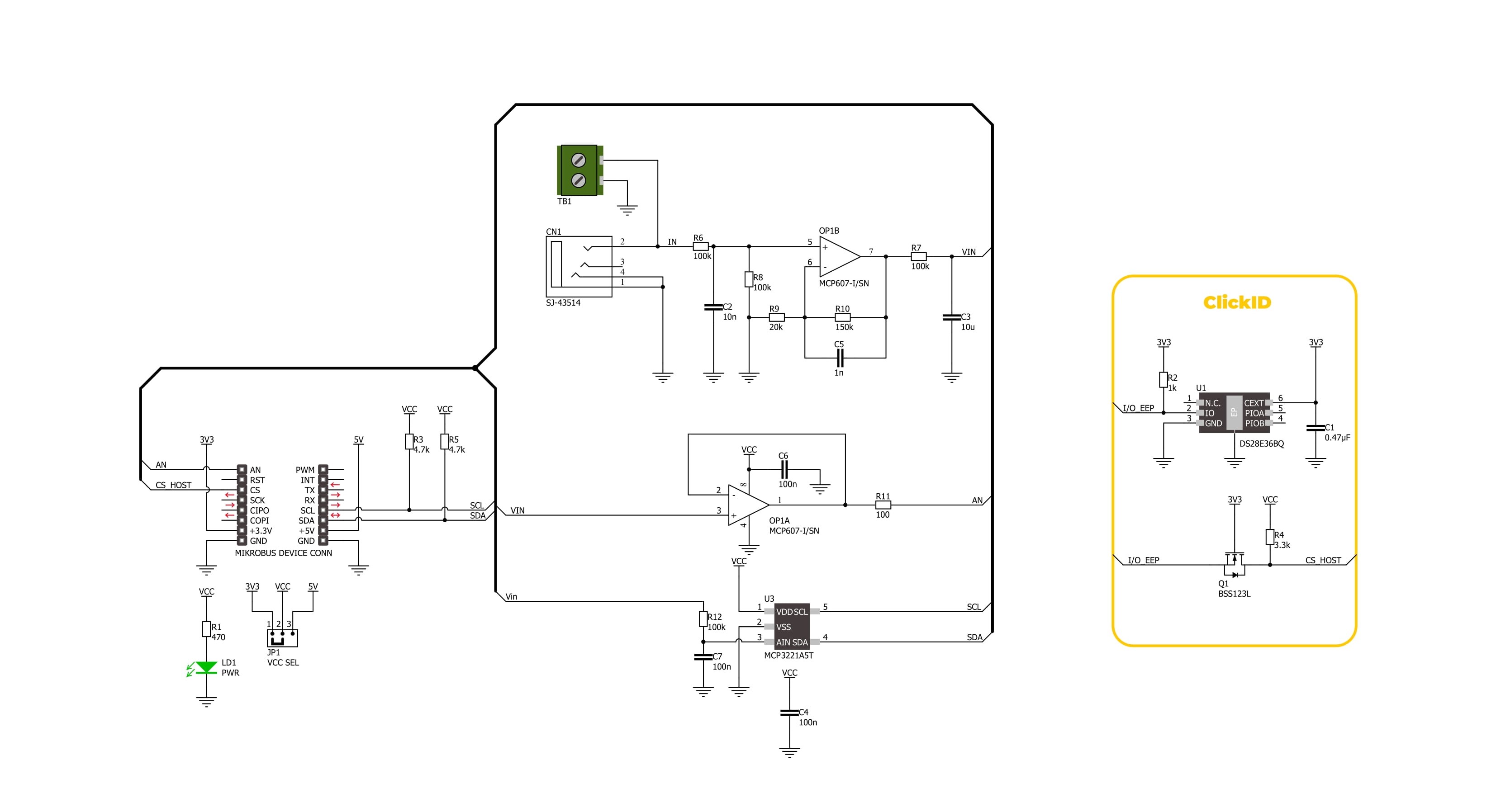
AC Current 2 Click is an add-on board made for the safe and accurate measurement of alternating current (AC) running through a conductor. It is specifically designed to work with a non-invasive current sensor, like AC Current Sensor - 30A that MIKROE offers, allowing the current in high-voltage installations such as mains wiring to be monitored without direct electrical contact. Thanks to its galvanic isolation and non-intrusive design, this board is ideal for applications such as current consumption monitoring, safety systems, and general AC current measurement where user safety and circuit integrity are priorities. The board is equipped with a 3.5mm jack connector and a connection terminal, offering flexibility depending on how the sensing probe needs to be connected in the user’s application. The sensing probe operates
on the principle of electromagnetic induction, much like a transformer, but without a primary winding. Instead, the AC current flowing through the conductor naturally generates the electromagnetic field necessary for sensing. The probe’s core is split, allowing it to clamp around the cable easily and measure current without modifying or affecting the electrical system. To maintain signal quality, the incoming voltage from the sensor passes through an RC filter that suppresses electromagnetic interference (EMI) and radio-frequency noise. After filtering, the signal is amplified by the MCP607 operational amplifier from Microchip, a rail-to-rail OpAmp with extremely low offset voltage and low bias current, ensuring that the measurement remains accurate and stable across different conditions. For digital signal processing, the
amplified voltage is then converted into a digital form by the MCP3221, a 12-bit successive approximation analog-to-digital converter (ADC) that communicates with the host MCU via a standard I2C interface. In addition to the digital output, AC Current 2 Click also offers a direct analog signal path via AN pin, enabling users to access the amplified signal without conversion if needed. This Click board™ can operate with either 3.3V or 5V logic voltage levels selected via the VCC SEL jumper. This way, both 3.3V and 5V capable MCUs can use the communication lines properly. Also, this Click board™ comes equipped with a library containing easy-to-use functions and an example code that can be used as a reference for further development.

Features overview
Development board
Nucleo-64 with STM32F103RB MCU offers a cost-effective and adaptable platform for developers to explore new ideas and prototype their designs. This board harnesses the versatility of the STM32 microcontroller, enabling users to select the optimal balance of performance and power consumption for their projects. It accommodates the STM32 microcontroller in the LQFP64 package and includes essential components such as a user LED, which doubles as an ARDUINO® signal, alongside user and reset push-buttons, and a 32.768kHz crystal oscillator for precise timing operations. Designed with expansion and flexibility in mind, the Nucleo-64 board features an ARDUINO® Uno V3 expansion connector and ST morpho extension pin
headers, granting complete access to the STM32's I/Os for comprehensive project integration. Power supply options are adaptable, supporting ST-LINK USB VBUS or external power sources, ensuring adaptability in various development environments. The board also has an on-board ST-LINK debugger/programmer with USB re-enumeration capability, simplifying the programming and debugging process. Moreover, the board is designed to simplify advanced development with its external SMPS for efficient Vcore logic supply, support for USB Device full speed or USB SNK/UFP full speed, and built-in cryptographic features, enhancing both the power efficiency and security of projects. Additional connectivity is
provided through dedicated connectors for external SMPS experimentation, a USB connector for the ST-LINK, and a MIPI® debug connector, expanding the possibilities for hardware interfacing and experimentation. Developers will find extensive support through comprehensive free software libraries and examples, courtesy of the STM32Cube MCU Package. This, combined with compatibility with a wide array of Integrated Development Environments (IDEs), including IAR Embedded Workbench®, MDK-ARM, and STM32CubeIDE, ensures a smooth and efficient development experience, allowing users to fully leverage the capabilities of the Nucleo-64 board in their projects.

Microcontroller Overview
MCU Card / MCU

Architecture
ARM Cortex-M3
MCU Memory (KB)
128
Silicon Vendor
STMicroelectronics
Pin count
64
RAM (Bytes)
20480
You complete me!
Accessories
Click Shield for Nucleo-64 comes equipped with two proprietary mikroBUS™ sockets, allowing all the Click board™ devices to be interfaced with the STM32 Nucleo-64 board with no effort. This way, Mikroe allows its users to add any functionality from our ever-growing range of Click boards™, such as WiFi, GSM, GPS, Bluetooth, ZigBee, environmental sensors, LEDs, speech recognition, motor control, movement sensors, and many more. More than 1537 Click boards™, which can be stacked and integrated, are at your disposal. The STM32 Nucleo-64 boards are based on the microcontrollers in 64-pin packages, a 32-bit MCU with an ARM Cortex M4 processor operating at 84MHz, 512Kb Flash, and 96KB SRAM, divided into two regions where the top section represents the ST-Link/V2 debugger and programmer while the bottom section of the board is an actual development board. These boards are controlled and powered conveniently through a USB connection to program and efficiently debug the Nucleo-64 board out of the box, with an additional USB cable connected to the USB mini port on the board. Most of the STM32 microcontroller pins are brought to the IO pins on the left and right edge of the board, which are then connected to two existing mikroBUS™ sockets. This Click Shield also has several switches that perform functions such as selecting the logic levels of analog signals on mikroBUS™ sockets and selecting logic voltage levels of the mikroBUS™ sockets themselves. Besides, the user is offered the possibility of using any Click board™ with the help of existing bidirectional level-shifting voltage translators, regardless of whether the Click board™ operates at a 3.3V or 5V logic voltage level. Once you connect the STM32 Nucleo-64 board with our Click Shield for Nucleo-64, you can access hundreds of Click boards™, working with 3.3V or 5V logic voltage levels.

The AC Current sensor is a non-invasive device designed for measuring alternating current. This split-core sensor can easily clip around live or neutral wires, making it versatile for various applications. It finds utility in the current measurement, monitoring, and protection of AC motors, lighting equipment, and air compressors. Key features of this sensor include an open size of 13mm x 13mm, a leading wire length of 1m, and a dielectric strength of 1000V AC/1min 5mA between the shell and output. It operates within a temperature range of -25°C to +70°C, adhering to a resistance grade of Grade B. The built-in sampling resistance (RL) is 186Ω, boasting a non-linearity of ±3%. The output mode ranges from 0 to 1V, accommodating input currents from 0 to 10A AC. With a fire resistance property in accordance with UL94-VO, this AC Current sensor ensures reliable and safe current monitoring in diverse electrical applications.

Used MCU Pins
mikroBUS™ mapper
Take a closer look
Click board™ Schematic
Step by step
Project assembly
Start by selecting your development board and Click board™. Begin with the Nucleo 64 with STM32F103RB MCU as your development board.


Track your results in real time
Application Output
1. Application Output - In Debug mode, the 'Application Output' window enables real-time data monitoring, offering direct insight into execution results. Ensure proper data display by configuring the environment correctly using the provided tutorial.

2. UART Terminal - Use the UART Terminal to monitor data transmission via a USB to UART converter, allowing direct communication between the Click board™ and your development system. Configure the baud rate and other serial settings according to your project's requirements to ensure proper functionality. For step-by-step setup instructions, refer to the provided tutorial.

3. Plot Output - The Plot feature offers a powerful way to visualize real-time sensor data, enabling trend analysis, debugging, and comparison of multiple data points. To set it up correctly, follow the provided tutorial, which includes a step-by-step example of using the Plot feature to display Click board™ readings. To use the Plot feature in your code, use the function: plot(*insert_graph_name*, variable_name);. This is a general format, and it is up to the user to replace 'insert_graph_name' with the actual graph name and 'variable_name' with the parameter to be displayed.

Software Support
Library Description
AC Current 2 Click demo application is developed using the NECTO Studio, ensuring compatibility with mikroSDK's open-source libraries and tools. Designed for plug-and-play implementation and testing, the demo is fully compatible with all development, starter, and mikromedia boards featuring a mikroBUS™ socket.
Example Description
This example demonstrates how to use the AC Current 2 Click board for reading the measurements from the AC Current sensor attached to the Click board input.
Key functions:
accurrent2_cfg_setup- This function initializes Click configuration structure to initial values.accurrent2_init- This function initializes all necessary pins and peripherals used for this Click board.accurrent2_read_current- This function reads the current measurement from the AC Current sensor (30A/1V).
Application Init
Initializes the driver and logger.
Application Task
Continuously reads the AC current value and logs the measured data in amperes (A).
Open Source
Code example
The complete application code and a ready-to-use project are available through the NECTO Studio Package Manager for direct installation in the NECTO Studio. The application code can also be found on the MIKROE GitHub account.
/*!
* @file main.c
* @brief AC Current 2 Click Example.
*
* # Description
* This example demonstrates how to use the AC Current 2 Click board for reading
* the measurements from the AC Current sensor attached to the Click board input.
*
* The demo application is composed of two sections:
*
* ## Application Init
* Initializes the driver and logger.
*
* ## Application Task
* Continuously reads the AC current value and logs the measured data in amperes (A).
*
* @note
* The AC Current sensor [MIKROE-2524] required for this Click board should
* have a specification of 30A/1A.
*
* @author Stefan Filipovic
*
*/
#include "board.h"
#include "log.h"
#include "accurrent2.h"
static accurrent2_t accurrent2; /**< AC Current 2 Click driver object. */
static log_t logger; /**< Logger object. */
void application_init ( void )
{
log_cfg_t log_cfg; /**< Logger config object. */
accurrent2_cfg_t accurrent2_cfg; /**< Click config object. */
/**
* Logger initialization.
* Default baud rate: 115200
* Default log level: LOG_LEVEL_DEBUG
* @note If USB_UART_RX and USB_UART_TX
* are defined as HAL_PIN_NC, you will
* need to define them manually for log to work.
* See @b LOG_MAP_USB_UART macro definition for detailed explanation.
*/
LOG_MAP_USB_UART( log_cfg );
log_init( &logger, &log_cfg );
log_info( &logger, " Application Init " );
// Click initialization.
accurrent2_cfg_setup( &accurrent2_cfg );
ACCURRENT2_MAP_MIKROBUS( accurrent2_cfg, MIKROBUS_1 );
err_t init_flag = accurrent2_init( &accurrent2, &accurrent2_cfg );
if ( ( ADC_ERROR == init_flag ) || ( I2C_MASTER_ERROR == init_flag ) )
{
log_error( &logger, " Communication init." );
for ( ; ; );
}
log_info( &logger, " Application Task " );
}
void application_task ( void )
{
float current = 0;
if ( ACCURRENT2_OK == accurrent2_read_current ( &accurrent2, ¤t ) )
{
log_printf( &logger, " AC Current : %.3f A\r\n\n", current );
Delay_ms ( 1000 );
}
}
int main ( void )
{
/* Do not remove this line or clock might not be set correctly. */
#ifdef PREINIT_SUPPORTED
preinit();
#endif
application_init( );
for ( ; ; )
{
application_task( );
}
return 0;
}
// ------------------------------------------------------------------------ END
Additional Support
Resources
Category:Current sensor


