Add low-power I2C repeat and acceleration to high-speed designs with NCA9700 and PIC18F57Q43
High-speed dual-channel bidirectional I2C repeater and level translator with integrated edge accelerators
Published Oct 14, 2025
Click board™
I2C Repeater Click
Dev. board
Curiosity Nano with PIC18F57Q43
Compiler
NECTO Studio
MCU
PIC18F57Q43
Extend and accelerate I2C communication with built-in voltage translation and signal buffering for high-speed embedded applications
A
A
Hardware Overview
How does it work?
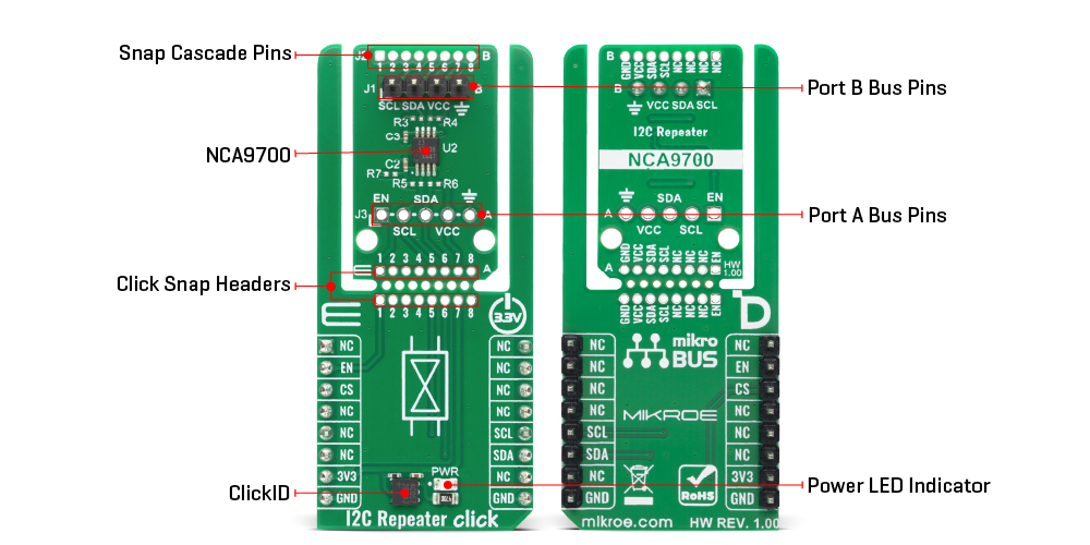
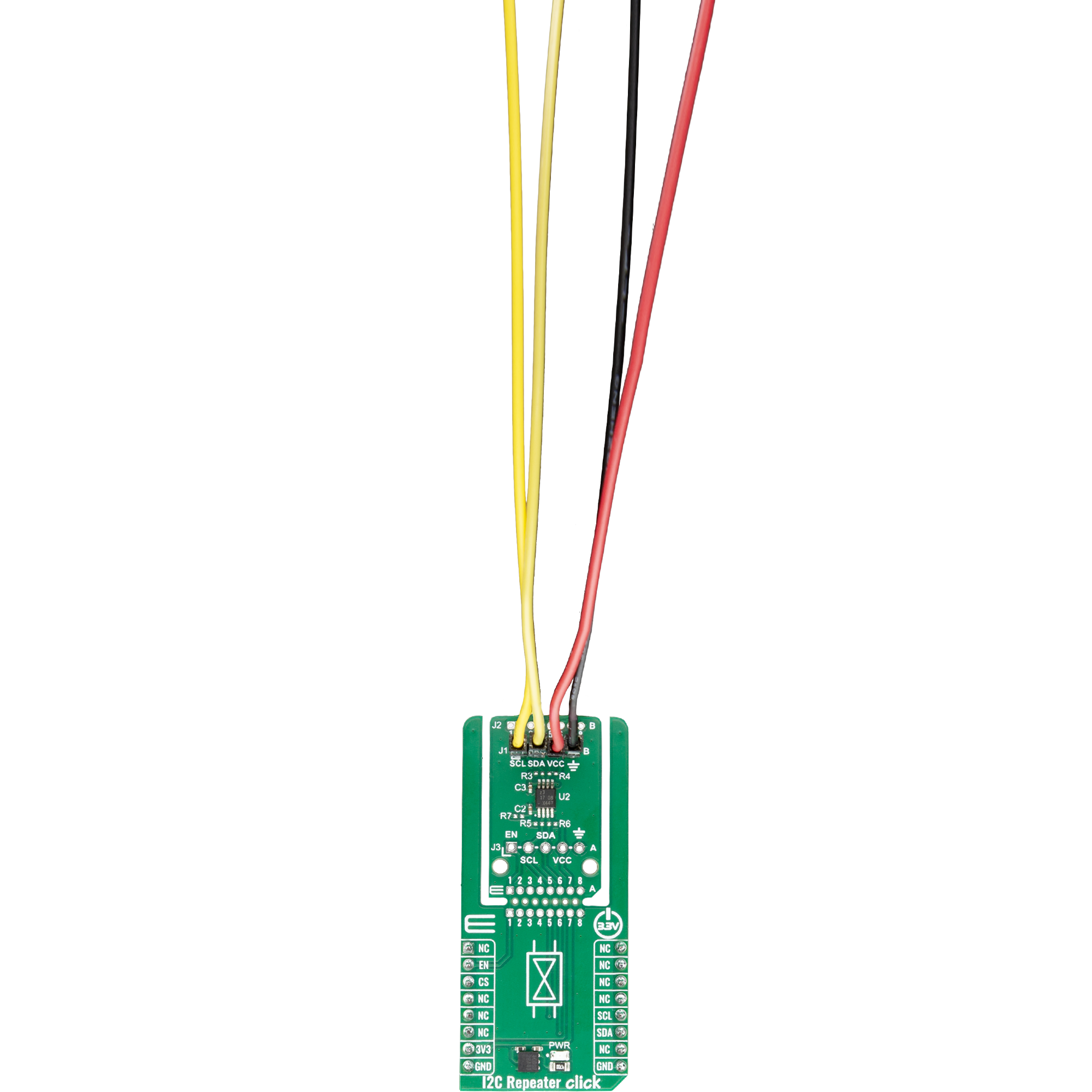
I2C Repeater Click is based on the NCA9700, a dual-channel bidirectional level translating I2C bus repeater/accelerator from NXP. This board is designed to extend and accelerate I2C communication between two buses while providing reliable voltage-level translation, buffering, and improved signal integrity for high-speed applications up to 1MHz (Fast-mode Plus operation). This makes I2C Repeater Click ideal for high-performance, low-power systems such as smartphones, tablets, portable medical devices, instrumentation and test equipment, IoT devices, and other power-sensitive applications where accelerated I2C communication is required. The high performance of the NCA9700 is achieved through integrated edge accelerators on all ports that speed up LOW-to-HIGH transitions of SCL and SDA signals. The NCA9700 buffers both clock and data lines while enabling up or down voltage translation between port A and port B, each independently operating from 1.08V to 3.6V to offer
flexibility for mixed-voltage systems. Each I/O pin features integrated 4.3kΩ pull-up resistors, eliminating the need for external resistors while allowing additional ones to be added to further improve rise times. Unlike devices based on pass-FET topology, the NCA9700 provides true signal buffering with no static or incremental offsets and guarantees lock-free operation thanks to its innovative buffer implementation. This Click board™ is designed in a unique format supporting the newly introduced MIKROE feature called "Click Snap." Unlike the standardized version of Click boards, this feature allows the main sensor/IC/module area to become movable by breaking the PCB, opening up many new possibilities for implementation. Thanks to the Snap feature, the NCA9700 can operate autonomously by accessing its signals directly on the pins marked 1-8. Additionally, the Snap part includes a specified and fixed screw hole position, enabling users to secure the Snap board in their desired location. In
addition to the I2C communication pins, the I2C Repeater Click also uses the EN pin that serves as the device enable input, allowing the user or system controller to activate or disable the repeater/accelerator. Besides, there is also an unpopulated J2 header at the top of the board, allowing for daisy-chaining and control of multiple Snap units in a series or in star, and their ports A and B can be exchanged. Only when the I2C clock stretching needs to be supported, the NCA9700 port A must be connected to the I2C host side and the NCA9700 port B to the I2C peripheral side. This Click board™ can be operated only with a 3.3V logic voltage level. The board must perform appropriate logic voltage level conversion before using MCUs with different logic levels. It also comes equipped with a library containing functions and example code that can be used as a reference for further development.
Features overview
Development board
PIC18F57Q43 Curiosity Nano evaluation kit is a cutting-edge hardware platform designed to evaluate microcontrollers within the PIC18-Q43 family. Central to its design is the inclusion of the powerful PIC18F57Q43 microcontroller (MCU), offering advanced functionalities and robust performance. Key features of this evaluation kit include a yellow user LED and a responsive
mechanical user switch, providing seamless interaction and testing. The provision for a 32.768kHz crystal footprint ensures precision timing capabilities. With an onboard debugger boasting a green power and status LED, programming and debugging become intuitive and efficient. Further enhancing its utility is the Virtual serial port (CDC) and a debug GPIO channel (DGI
GPIO), offering extensive connectivity options. Powered via USB, this kit boasts an adjustable target voltage feature facilitated by the MIC5353 LDO regulator, ensuring stable operation with an output voltage ranging from 1.8V to 5.1V, with a maximum output current of 500mA, subject to ambient temperature and voltage constraints.

Microcontroller Overview
MCU Card / MCU

Architecture
PIC
MCU Memory (KB)
128
Silicon Vendor
Microchip
Pin count
48
RAM (Bytes)
8196
You complete me!
Accessories
Curiosity Nano Base for Click boards is a versatile hardware extension platform created to streamline the integration between Curiosity Nano kits and extension boards, tailored explicitly for the mikroBUS™-standardized Click boards and Xplained Pro extension boards. This innovative base board (shield) offers seamless connectivity and expansion possibilities, simplifying experimentation and development. Key features include USB power compatibility from the Curiosity Nano kit, alongside an alternative external power input option for enhanced flexibility. The onboard Li-Ion/LiPo charger and management circuit ensure smooth operation for battery-powered applications, simplifying usage and management. Moreover, the base incorporates a fixed 3.3V PSU dedicated to target and mikroBUS™ power rails, alongside a fixed 5.0V boost converter catering to 5V power rails of mikroBUS™ sockets, providing stable power delivery for various connected devices.

Used MCU Pins
mikroBUS™ mapper
Take a closer look
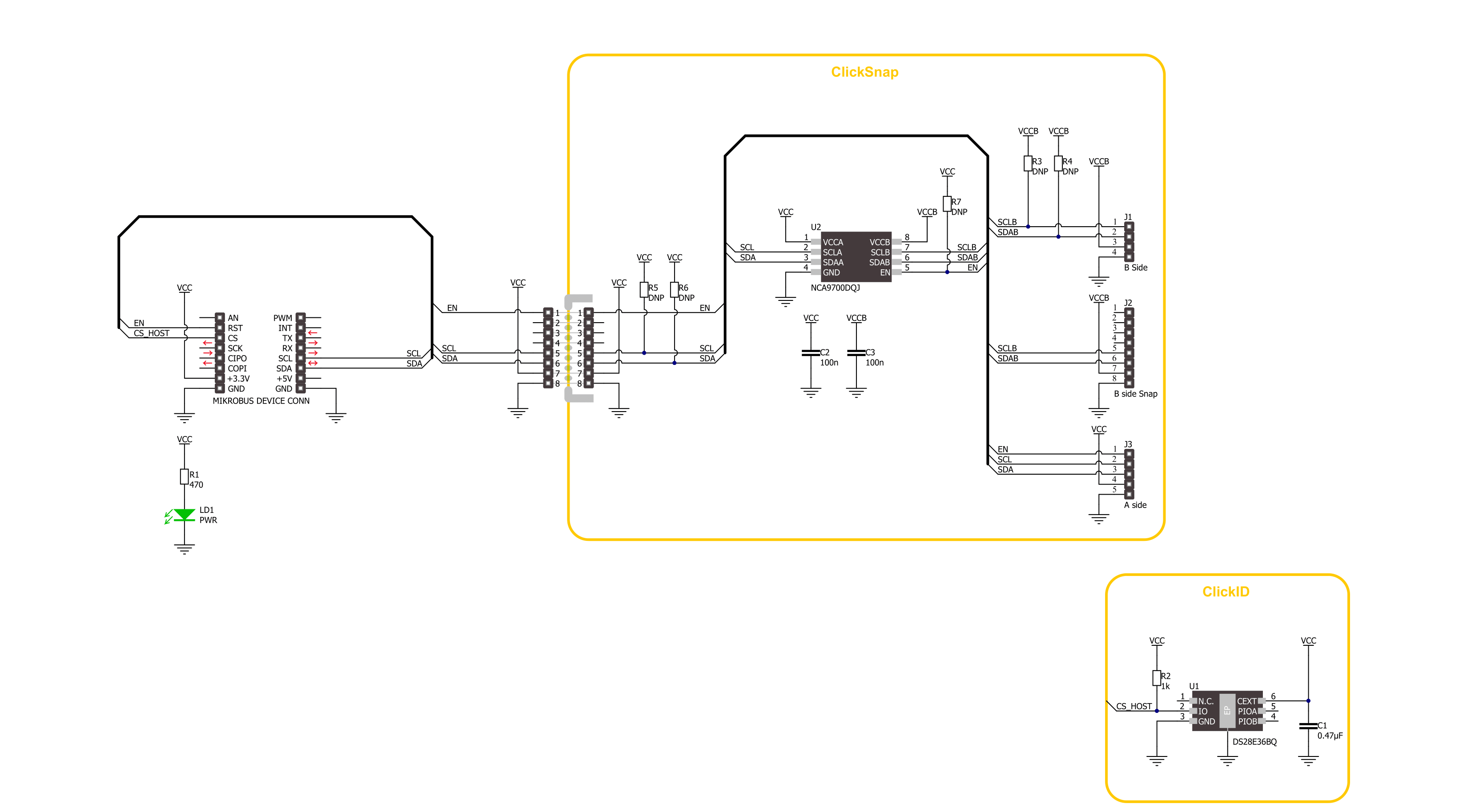
Click board™ Schematic
Step by step
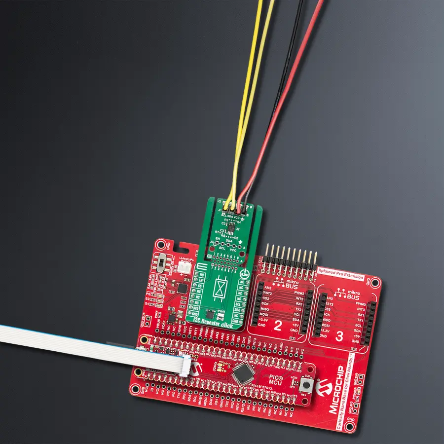
Project assembly

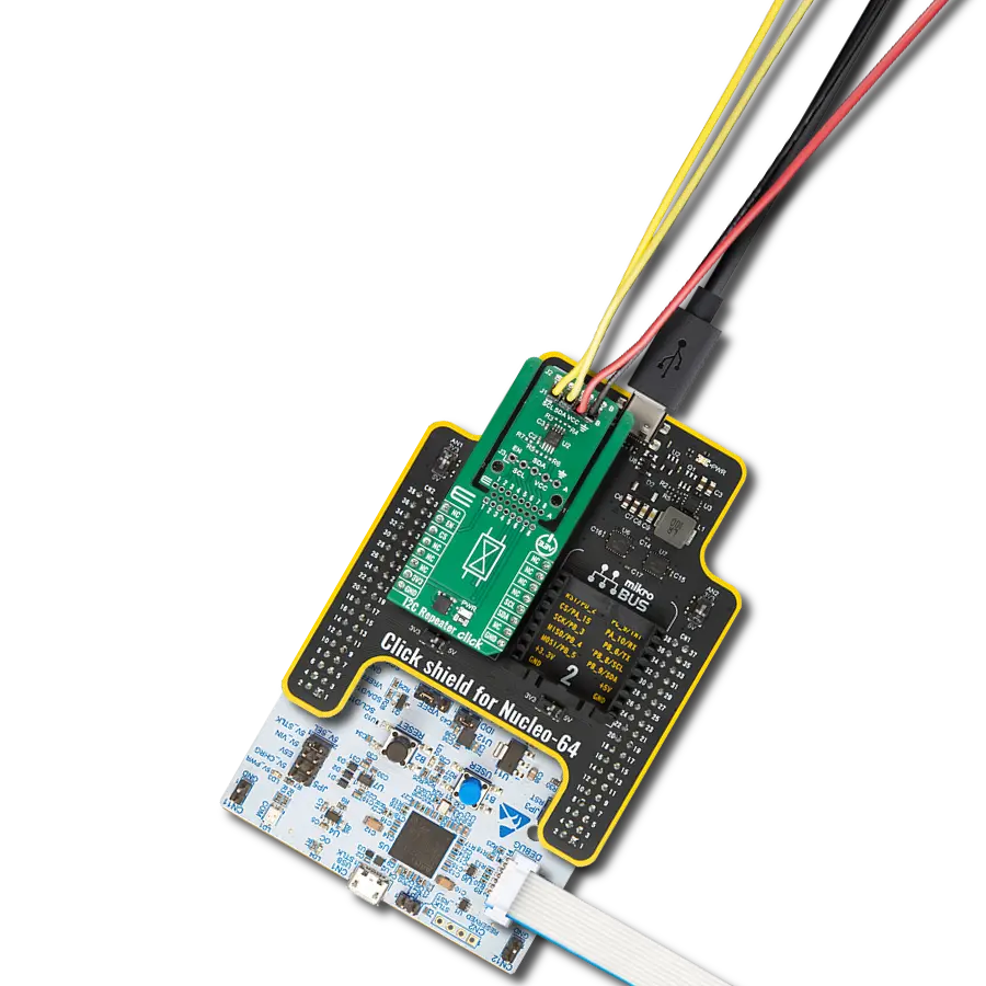
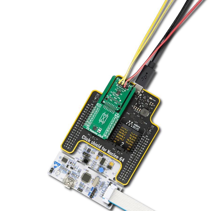
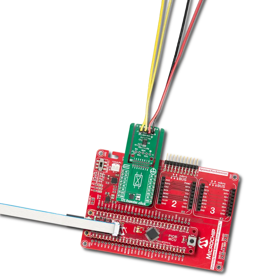
Start by selecting your development board and Click board™. Begin with the Curiosity Nano with PIC18F57Q43 as your development board.


Track your results in real time
Application Output
1. Application Output - In Debug mode, the 'Application Output' window enables real-time data monitoring, offering direct insight into execution results. Ensure proper data display by configuring the environment correctly using the provided tutorial.

2. UART Terminal - Use the UART Terminal to monitor data transmission via a USB to UART converter, allowing direct communication between the Click board™ and your development system. Configure the baud rate and other serial settings according to your project's requirements to ensure proper functionality. For step-by-step setup instructions, refer to the provided tutorial.

3. Plot Output - The Plot feature offers a powerful way to visualize real-time sensor data, enabling trend analysis, debugging, and comparison of multiple data points. To set it up correctly, follow the provided tutorial, which includes a step-by-step example of using the Plot feature to display Click board™ readings. To use the Plot feature in your code, use the function: plot(*insert_graph_name*, variable_name);. This is a general format, and it is up to the user to replace 'insert_graph_name' with the actual graph name and 'variable_name' with the parameter to be displayed.

Software Support
Library Description
I2C Repeater Click demo application is developed using the NECTO Studio, ensuring compatibility with mikroSDK's open-source libraries and tools. Designed for plug-and-play implementation and testing, the demo is fully compatible with all development, starter, and mikromedia boards featuring a mikroBUS™ socket.
Example Description
This example demonstrates the communication through the I2C Repeater Click board. It initializes the device, sets the slave I2C address of an external I2C sensor (e.g. 6DOF IMU 11 Click), and reads its device ID register, verifying if the expected ID is returned.
Key functions:
i2crepeater_cfg_setup- This function initializes Click configuration structure to initial values.i2crepeater_init- This function initializes all necessary pins and peripherals used for this Click board.i2crepeater_enable_device- This function enables the device by setting the EN pin to high logic state.i2crepeater_set_i2c_address- This function sets the slave address for I2C communication.i2crepeater_i2c_read_reg- This function reads data from a specific register of the I2C slave.
Application Init
Initializes the logger and the I2C Repeater Click, then enables the device.
Application Task
Sets the I2C address of a connected I2C sensor and reads its device ID, then logs whether the returned ID matches the expected value.
Open Source
Code example
The complete application code and a ready-to-use project are available through the NECTO Studio Package Manager for direct installation in the NECTO Studio. The application code can also be found on the MIKROE GitHub account.
/*!
 * @file main.c
 * @brief I2C Repeater Click example
 *
 * # Description
 * This example demonstrates the communication through the I2C Repeater Click board.
 * It initializes the device, sets the slave I2C address of an external I2C sensor (e.g. 6DOF IMU 11 Click),
 * and reads its device ID register, verifying if the expected ID is returned.
 *
 * The demo application is composed of two sections :
 *
 * ## Application Init
 * Initializes the logger and the I2C Repeater Click, then enables the device.
 *
 * ## Application Task
 * Sets the I2C address of a connected I2C sensor and reads its device ID,
 * then logs whether the returned ID matches the expected value.
 *
 * @note
 * Make sure to provide the power supply to VCCB side for the connected I2C sensor.
 *
 * @author Stefan Filipovic
 *
 */

#include "board.h"
#include "log.h"
#include "i2crepeater.h"

#define DEVICE_NAME             "6DOF IMU 11 Click"
#define DEVICE_SLAVE_ADDRESS    0x0E
#define DEVICE_REG_ID           0x00
#define DEVICE_ID               0x2D

static i2crepeater_t i2crepeater;
static log_t logger;

void application_init ( void )
{
    log_cfg_t log_cfg;  /**< Logger config object. */
    i2crepeater_cfg_t i2crepeater_cfg;  /**< Click config object. */

    /**
     * Logger initialization.
     * Default baud rate: 115200
     * Default log level: LOG_LEVEL_DEBUG
     * @note If USB_UART_RX and USB_UART_TX
     * are defined as HAL_PIN_NC, you will
     * need to define them manually for log to work.
     * See @b LOG_MAP_USB_UART macro definition for detailed explanation.
     */
    LOG_MAP_USB_UART( log_cfg );
    log_init( &logger, &log_cfg );
    log_info( &logger, " Application Init " );

    // Click initialization.
    i2crepeater_cfg_setup( &i2crepeater_cfg );
    I2CREPEATER_MAP_MIKROBUS( i2crepeater_cfg, MIKROBUS_1 );
    if ( I2C_MASTER_ERROR == i2crepeater_init( &i2crepeater, &i2crepeater_cfg ) )
    {
        log_error( &logger, " Communication init." );
        for ( ; ; );
    }

    i2crepeater_enable_device ( &i2crepeater );

    log_info( &logger, " Application Task " );
}

void application_task ( void )
{
    uint8_t device_id = 0;
    if ( I2CREPEATER_OK == i2crepeater_set_i2c_address ( &i2crepeater, DEVICE_SLAVE_ADDRESS ) )
    {
        if ( I2CREPEATER_OK == i2crepeater_i2c_read_reg ( &i2crepeater, DEVICE_REG_ID, &device_id, 1 ) )
        {
            log_printf( &logger, " %s - Device ID: 0x%.2X - %s\r\n\n",
                        ( char * ) DEVICE_NAME, ( uint16_t ) device_id,
                        ( char * ) ( ( DEVICE_ID == device_id ) ? "OK" : "NOK" ) );
        }
        Delay_ms ( 1000 );
    }
}

int main ( void )
{
    /* Do not remove this line or clock might not be set correctly. */
    #ifdef PREINIT_SUPPORTED
    preinit();
    #endif

    application_init( );

    for ( ; ; )
    {
        application_task( );
    }

    return 0;
}

// ------------------------------------------------------------------------ END
Additional Support
Resources
Category:I2C