Generate secure and certified 256-bit random numbers with RNG90 and PIC32MZ2048EFM100
Secure and certified random number generation solution for robust cryptographic systems

Published May 14, 2025
Click board™
RNG 2 Click
Dev. board
Curiosity PIC32 MZ EF
Compiler
NECTO Studio
MCU
PIC32MZ2048EFM100
Secure, NIST-certified 256-bit random number generation with tamper detection
A
A
Hardware Overview
How does it work?
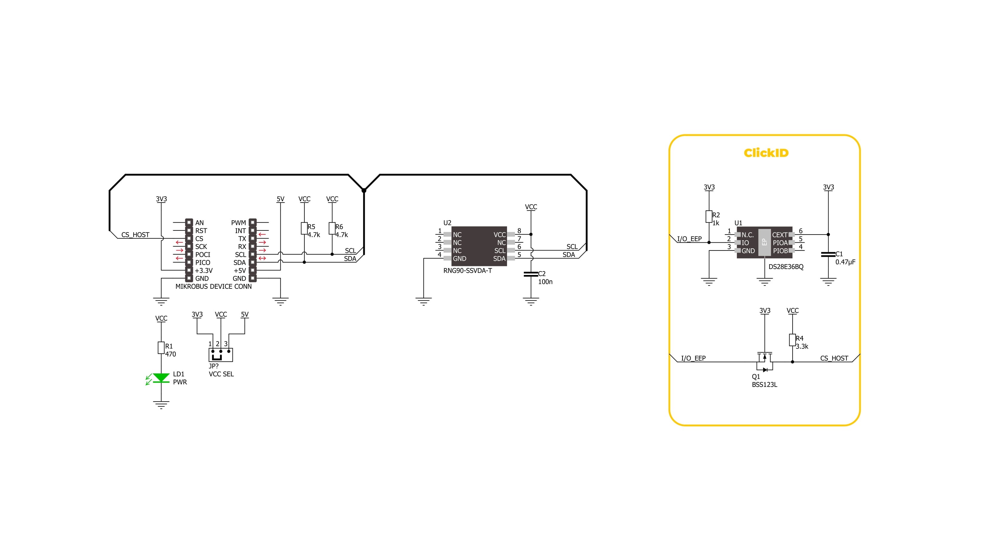
RNG 2 Click is based on the RNG90, a secure Random Number Generator (RNG) from Microchip fully compliant with the NIST SP 800-90A/B/C standards. This Click board™ is designed to meet the stringent requirements of modern cryptographic systems, where the strength of generated random numbers directly influences the overall system security. True random number generation is critical in cryptographic applications such as key generation, digital signatures, password creation, nonce generation, random challenges, and initialization vectors. The RNG90 IC addresses these needs by producing a 256-bit random number with each Random command execution, offering a robust security strength of 128 bits. Independently
validated for randomness through a NIST-certified laboratory, the RNG90 guarantees trustworthy operation in sensitive applications. As part of Microchip’s CryptoAuthentication™ product line, it integrates into systems demanding secure, ready-to-use randomness without requiring any additional configuration. RNG 2 Click communicates over a standard I2C interface operating at up to 400kHz, making it simple to integrate with a wide range of host MCUs. It also features a unique 72-bit serial number and advanced hardware-based security mechanisms such as an active shield for protection against invasive physical attacks, tamper detection for abnormal voltage conditions, and temperature-based tamper monitoring. With these features,
RNG 2 Click is ideally suited for use in cryptographic systems, password management tools, gaming platforms, cryptocurrency hardware wallets, scientific experiments, and even aerospace and defense technologies, where secure and certified random number generation is a fundamental requirement. This Click board™ can operate with either 3.3V or 5V logic voltage levels selected via the VCC SEL jumper. This way, both 3.3V and 5V capable MCUs can use the communication lines properly. Also, this Click board™ comes equipped with a library containing easy-to-use functions and an example code that can be used as a reference for further development.

Features overview
Development board
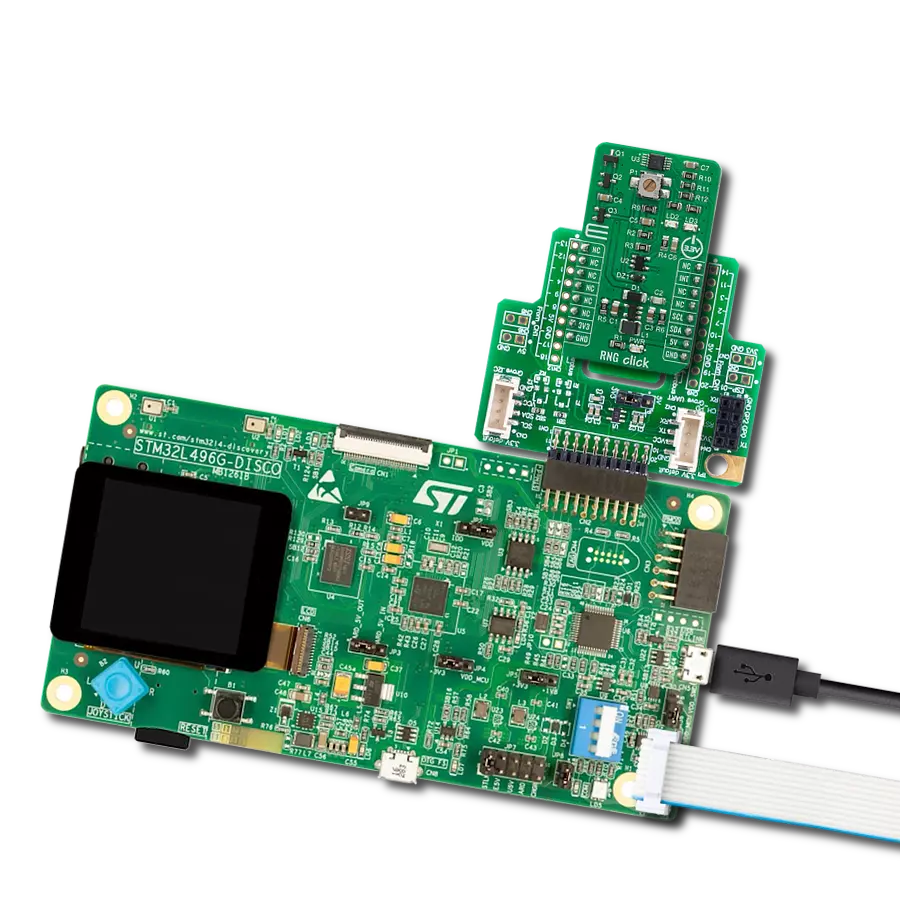
Curiosity PIC32 MZ EF development board is a fully integrated 32-bit development platform featuring the high-performance PIC32MZ EF Series (PIC32MZ2048EFM) that has a 2MB Flash, 512KB RAM, integrated FPU, Crypto accelerator, and excellent connectivity options. It includes an integrated programmer and debugger, requiring no additional hardware. Users can expand
functionality through MIKROE mikroBUS™ Click™ adapter boards, add Ethernet connectivity with the Microchip PHY daughter board, add WiFi connectivity capability using the Microchip expansions boards, and add audio input and output capability with Microchip audio daughter boards. These boards are fully integrated into PIC32’s powerful software framework, MPLAB Harmony,
which provides a flexible and modular interface to application development a rich set of inter-operable software stacks (TCP-IP, USB), and easy-to-use features. The Curiosity PIC32 MZ EF development board offers expansion capabilities making it an excellent choice for a rapid prototyping board in Connectivity, IOT, and general-purpose applications.

Microcontroller Overview
MCU Card / MCU

Architecture
PIC32
MCU Memory (KB)
2048
Silicon Vendor
Microchip
Pin count
100
RAM (Bytes)
524288
Used MCU Pins
mikroBUS™ mapper
Take a closer look
Click board™ Schematic
Step by step
Project assembly

Start by selecting your development board and Click board™. Begin with the Curiosity PIC32 MZ EF as your development board.


Track your results in real time
Application Output
1. Application Output - In Debug mode, the 'Application Output' window enables real-time data monitoring, offering direct insight into execution results. Ensure proper data display by configuring the environment correctly using the provided tutorial.

2. UART Terminal - Use the UART Terminal to monitor data transmission via a USB to UART converter, allowing direct communication between the Click board™ and your development system. Configure the baud rate and other serial settings according to your project's requirements to ensure proper functionality. For step-by-step setup instructions, refer to the provided tutorial.

3. Plot Output - The Plot feature offers a powerful way to visualize real-time sensor data, enabling trend analysis, debugging, and comparison of multiple data points. To set it up correctly, follow the provided tutorial, which includes a step-by-step example of using the Plot feature to display Click board™ readings. To use the Plot feature in your code, use the function: plot(*insert_graph_name*, variable_name);. This is a general format, and it is up to the user to replace 'insert_graph_name' with the actual graph name and 'variable_name' with the parameter to be displayed.

Software Support
Library Description
RNG 2 Click demo application is developed using the NECTO Studio, ensuring compatibility with mikroSDK's open-source libraries and tools. Designed for plug-and-play implementation and testing, the demo is fully compatible with all development, starter, and mikromedia boards featuring a mikroBUS™ socket.
Example Description
This example demonstrates the use of the RNG 2 Click board by periodically reading and logging random numbers generated by the device.
Key functions:
rng2_cfg_setup- This function initializes Click configuration structure to initial values.rng2_init- This function initializes all necessary pins and peripherals used for this Click board.rng2_default_cfg- This function executes a default configuration of RNG 2 Click board.rng2_read_random_num- This function requests and reads a 32-byte random number from the RNG 2 Click board.
Application Init
Initializes the logger and the Click board driver, then applies the default configuration.
Application Task
Reads and displays a 32-byte random number from the device every second.
Open Source
Code example
The complete application code and a ready-to-use project are available through the NECTO Studio Package Manager for direct installation in the NECTO Studio. The application code can also be found on the MIKROE GitHub account.
/*!
 * @file main.c
 * @brief RNG 2 Click example
 *
 * # Description
 * This example demonstrates the use of the RNG 2 Click board by periodically reading
 * and logging random numbers generated by the device.
 *
 * The demo application is composed of two sections :
 *
 * ## Application Init
 * Initializes the logger and the Click board driver, then applies the default configuration.
 *
 * ## Application Task
 * Reads and displays a 32-byte random number from the device every second.
 *
 * @author Stefan Filipovic
 *
 */

#include "board.h"
#include "log.h"
#include "rng2.h"

static rng2_t rng2;
static log_t logger;

void application_init ( void )
{
    log_cfg_t log_cfg;  /**< Logger config object. */
    rng2_cfg_t rng2_cfg;  /**< Click config object. */

    /**
     * Logger initialization.
     * Default baud rate: 115200
     * Default log level: LOG_LEVEL_DEBUG
     * @note If USB_UART_RX and USB_UART_TX
     * are defined as HAL_PIN_NC, you will
     * need to define them manually for log to work.
     * See @b LOG_MAP_USB_UART macro definition for detailed explanation.
     */
    LOG_MAP_USB_UART( log_cfg );
    log_init( &logger, &log_cfg );
    log_info( &logger, " Application Init " );

    // Click initialization.
    rng2_cfg_setup( &rng2_cfg );
    RNG2_MAP_MIKROBUS( rng2_cfg, MIKROBUS_1 );
    if ( RNG2_OK != rng2_init( &rng2, &rng2_cfg ) )
    {
        log_error( &logger, " Communication init." );
        for ( ; ; );
    }

    if ( RNG2_ERROR == rng2_default_cfg ( &rng2 ) )
    {
        log_error( &logger, " Default configuration." );
        for ( ; ; );
    }

    log_info( &logger, " Application Task " );
}

void application_task ( void )
{
    if ( RNG2_OK == rng2_read_random_num ( &rng2 ) )
    {
        log_printf ( &logger, " Random number: " );
        for ( uint8_t cnt = 0; cnt < rng2.rsp_pkt.data_len; cnt++ )
        {
            log_printf ( &logger, "%.2X", ( uint16_t ) rng2.rsp_pkt.data_buf[ cnt ] );
        }
        log_printf ( &logger, "\r\n\n" );
    }
    Delay_ms ( 1000 );
}

int main ( void )
{
    /* Do not remove this line or clock might not be set correctly. */
    #ifdef PREINIT_SUPPORTED
    preinit();
    #endif

    application_init( );

    for ( ; ; )
    {
        application_task( );
    }

    return 0;
}

// ------------------------------------------------------------------------ END
Additional Support
Resources
Category:Encryption