Monitor heart rate and vital signs with high accuracy using the SFH 7074 and STM32L4R9AI
Biomonitoring sensing solution for heart rate and vital sign monitoring
Published Feb 26, 2025
Click board™
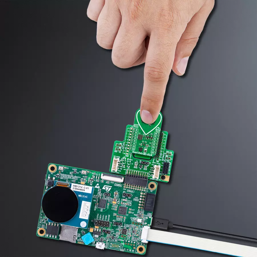
Heart Rate 13 Click
Dev. board
Discovery kit with STM32L4R9AI MCU
Compiler
NECTO Studio
MCU
STM32L4R9AI
Real-time heart rate and vital signs monitor ideal for wearables, IoT projects and medical applications
A
A
Hardware Overview
How does it work?
Heart Rate 13 Click is based on the SFH 7074, a high-performance biomonitoring sensor from ams OSRAM, designed for precise and reliable vital sign monitoring. This sensor is optimized for photoplethysmography (PPG) applications, providing a strong and accurate optical signal while minimizing the effects of optical crosstalk through an integrated light barrier. Additionally, the SFH 7074 meets stringent ESD protection standards (1.5 kV acc. to ANSI/ESDA/JEDEC JS-001 HBM), ensuring robustness in various operating environments. Due to its advanced design, this sensor is widely used in digital diagnostic applications like wearable devices, fitness trackers, and medical diagnostic equipment, enabling accurate heart rate, oxygen saturation, and other biometric measurements. Heart Rate 13 Click incorporates the ADPD1080, a photometric front-end from Analog Devices, to ensure optimal signal processing and high measurement accuracy. This front end is essential for handling the optical
signals received from the SFH 7074, as it includes a 14-bit analog-to-digital converter (ADC) and a 20-bit burst accumulator, allowing precise digital conversion of the detected biometric data. The ADPD1080 controls the sensor's light-emitting diodes (LEDs), stimulating and capturing the reflected optical signals to generate accurate readings. A key advantage of this front-end is its built-in signal processing capabilities, which eliminate the need for external optical filters or DC cancellation circuits. It suppresses signal offset and reduces corruption caused by modulated interference, commonly introduced by ambient light sources, ensuring stable and reliable biometric measurements. This Click board™ establishes communication with the host MCU through a standard I2C interface of the ADPD1080 operating at 1.8V. Additionally, it features two general-purpose I/O pins (IO0 and IO1), which are connected to the default mikroBUS™ socket's PWM and INT positions. These pins serve as
interrupt sources and offer various clocking options, allowing for greater flexibility in application design and integration with different processing platforms. The SFH 7074 operates at a 3.3V supply and requires no specific power-up sequence. However, the ADPD1080 photometric front-end requires a 1.8V supply for its analog and digital core to function correctly. To accommodate this requirement, Heart Rate 13 Click integrates a small low-dropout (LDO) voltage regulator, the BH18PB1WHFV, which converts the 3.3V mikroBUS™ power rail into a stable 1.8V supply, ensuring proper operation of the ADPD1080. This Click board™ can be operated only with a 3.3V logic voltage level. The board must perform appropriate logic voltage level conversion before using MCUs with different logic levels. It also comes equipped with a library containing functions and example code that can be used as a reference for further development.

Features overview
Development board
Discovery kit with STM32L4R9AI MCU is a complete demonstration and development platform for the STMicroelectronics Arm® Cortex®-M4 core-based STM32L4R9AI microcontroller. Leveraging the innovative ultra-low-power oriented features, 640 Kbytes of embedded RAM, graphics performance (Chrom-ART Accelerator™), and DSISM controller offered by the STM32L4R9AI, the 32L4R9IDISCOVERY kit enables users to easily prototype applications with state-of-the-art energy efficiency, as well as providing stunning audio and graphics rendering with direct support for an AMOLED DSI round display. For even more user friendliness, the on-board ST-LINK/V2-1 debugger provides out-of-the-box programming and
debugging capabilities. The STM32L4R9AI microcontroller features four I2Cs, five USARTs, one ULP UART, three SPIs, two SAIs, one SDIO, one USB 2.0 full-speed OTG, two CANs, one FMC parallel synchronous interface, one 12 bit ADC, one 12-bit DAC, two ULP analog comparators, two op-amps, one two data-lane DSI display, one digital filter for sigma-delta modulation and SWP interface, two Octo-SPI interfaces, an 8- to 14-bit camera interface, one touch-sensing controller interface, JTAG, and SWD debugging support. This Discovery board offers everything users need to get started quickly and develop applications easily. The hardware features on the board help to evaluate the following peripherals: USB OTG FS, microSD™
card, 8-bit camera interface, 16-Mbit PSRAM, PMOD, and STMod+ connectors, IDD measurement, full-duplex I2S with an audio codec and stereo headset jack including an analog microphone, DFSDM with a pair of MEMS digital microphones on board, 512-Mbit Octo-SPI Flash memory device, I2C extension connector, 1.2" AMOLED display using a one data-lane DSI interface with a capacitive touch panel. The ARDUINO® compatible connectors expand the functionality with a wide choice of specialized shields. The integrated ST-LINK/V2-1 provides an embedded in-circuit debugger and programmer for the STM32 MCU.

Microcontroller Overview
MCU Card / MCU
Architecture
ARM Cortex-M4
MCU Memory (KB)
2048
Silicon Vendor
STMicroelectronics
Pin count
169
RAM (Bytes)
655360
Used MCU Pins
mikroBUS™ mapper
Take a closer look
Click board™ Schematic

Step by step
Project assembly

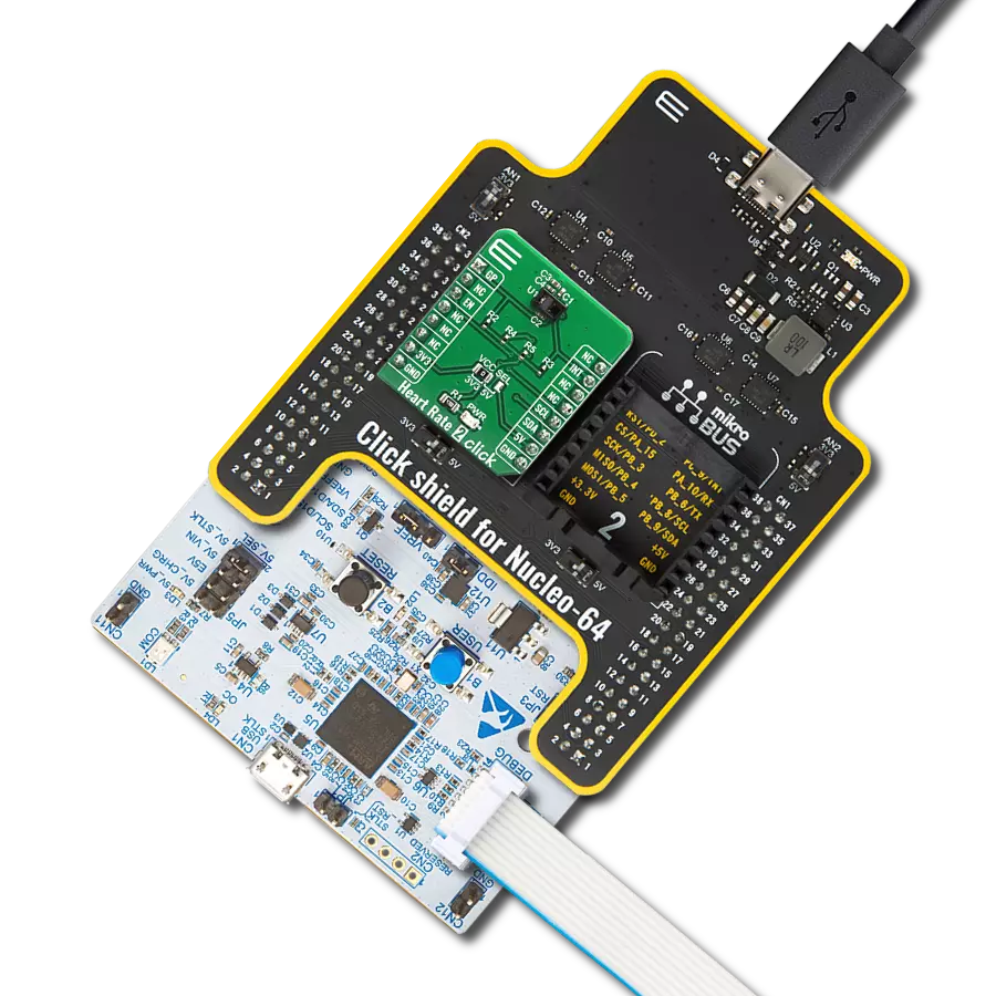
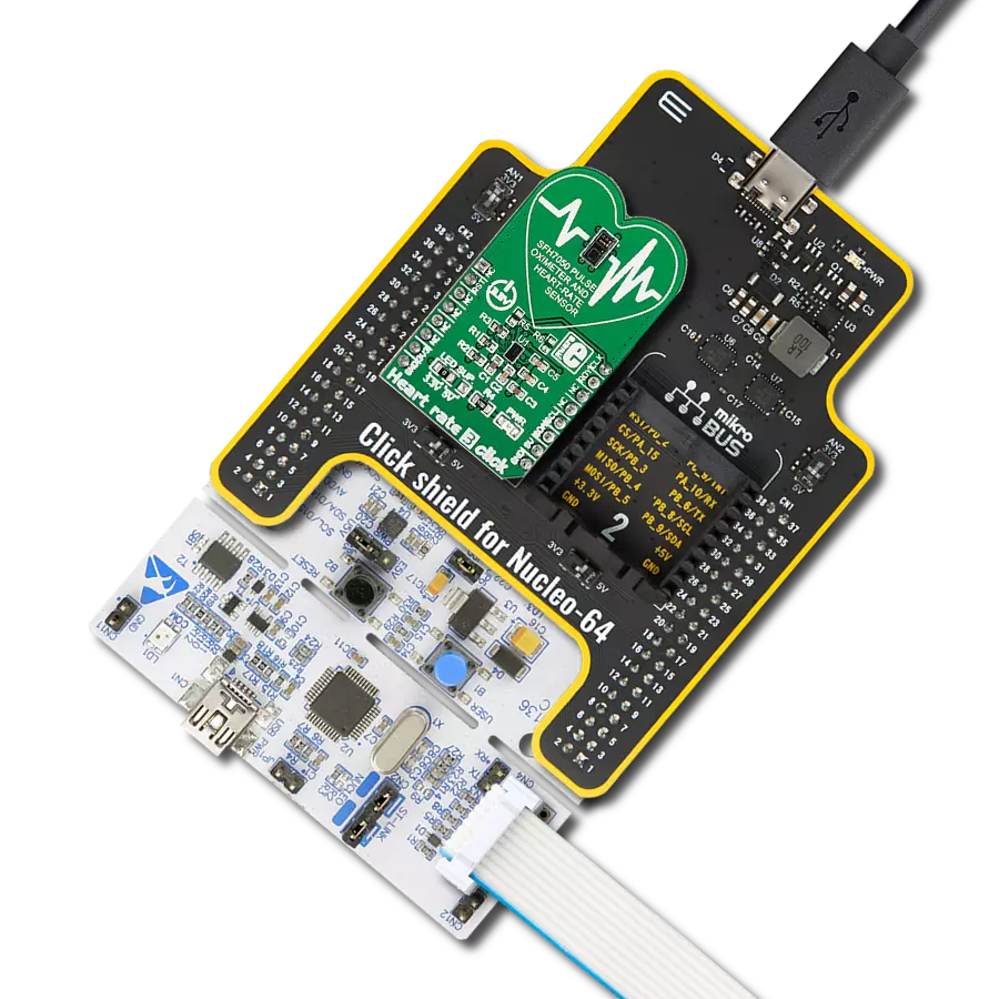
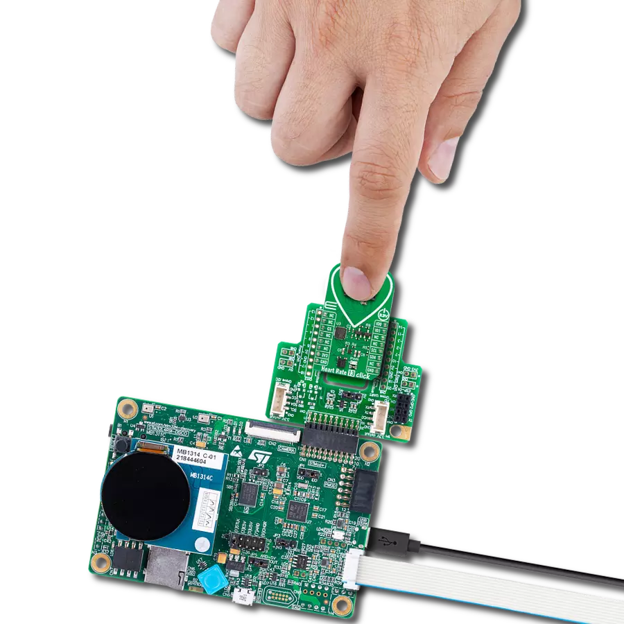
Start by selecting your development board and Click board™. Begin with the Discovery kit with STM32L4R9AI MCU as your development board.


Track your results in real time
Application Output
1. Application Output - In Debug mode, the 'Application Output' window enables real-time data monitoring, offering direct insight into execution results. Ensure proper data display by configuring the environment correctly using the provided tutorial.

2. UART Terminal - Use the UART Terminal to monitor data transmission via a USB to UART converter, allowing direct communication between the Click board™ and your development system. Configure the baud rate and other serial settings according to your project's requirements to ensure proper functionality. For step-by-step setup instructions, refer to the provided tutorial.

3. Plot Output - The Plot feature offers a powerful way to visualize real-time sensor data, enabling trend analysis, debugging, and comparison of multiple data points. To set it up correctly, follow the provided tutorial, which includes a step-by-step example of using the Plot feature to display Click board™ readings. To use the Plot feature in your code, use the function: plot(*insert_graph_name*, variable_name);. This is a general format, and it is up to the user to replace 'insert_graph_name' with the actual graph name and 'variable_name' with the parameter to be displayed.

Software Support
Library Description
Heart Rate 13 Click demo application is developed using the NECTO Studio, ensuring compatibility with mikroSDK's open-source libraries and tools. Designed for plug-and-play implementation and testing, the demo is fully compatible with all development, starter, and mikromedia boards featuring a mikroBUS™ socket.
Example Description
This example demonstrates the use of Heart Rate 13 Click board by reading and displaying the PPG measurements which can be visualized on the SerialPlot application.
Key functions:
heartrate13_cfg_setup- Config Object Initialization function.heartrate13_init- Initialization function.heartrate13_default_cfg- Click Default Configuration function.heartrate13_get_pd_data- This function waits for the data ready interrupt and then reads data from photodiodes PD1, PD2, and PD3.heartrate13_set_mode- This function sets the device operating mode.heartrate13_sw_reset- This function executes software reset of the device.
Application Init
Initializes the driver and performs the Click default configuration for heart rate measurement.
Application Task
Waits for the data ready interrupt, then reads the PPG measurements and displays it on the USB UART (SerialPlot).
Open Source
Code example
The complete application code and a ready-to-use project are available through the NECTO Studio Package Manager for direct installation in the NECTO Studio. The application code can also be found on the MIKROE GitHub account.
/*!
 * @file main.c
 * @brief Heart Rate 13 Click example
 *
 * # Description
 * This example demonstrates the use of Heart Rate 13 Click board by reading and displaying
 * the PPG measurements which can be visualized on the SerialPlot application.
 *
 * The demo application is composed of two sections :
 *
 * ## Application Init
 * Initializes the driver and performs the Click default configuration for heart rate measurement.
 *
 * ## Application Task
 * Waits for the data ready interrupt, then reads the PPG measurements and displays it on the
 * USB UART (SerialPlot).
 *
 * @note
 * We recommend using the SerialPlot tool for data visualizing.
 *
 * @author Stefan Filipovic
 *
 */

#include "board.h"
#include "log.h"
#include "heartrate13.h"

static heartrate13_t heartrate13;
static log_t logger;

void application_init ( void )
{
    log_cfg_t log_cfg;  /**< Logger config object. */
    heartrate13_cfg_t heartrate13_cfg;  /**< Click config object. */

    /**
     * Logger initialization.
     * Default baud rate: 115200
     * Default log level: LOG_LEVEL_DEBUG
     * @note If USB_UART_RX and USB_UART_TX
     * are defined as HAL_PIN_NC, you will
     * need to define them manually for log to work.
     * See @b LOG_MAP_USB_UART macro definition for detailed explanation.
     */
    LOG_MAP_USB_UART( log_cfg );
    log_init( &logger, &log_cfg );
    log_info( &logger, " Application Init " );

    // Click initialization.
    heartrate13_cfg_setup( &heartrate13_cfg );
    HEARTRATE13_MAP_MIKROBUS( heartrate13_cfg, MIKROBUS_1 );
    if ( I2C_MASTER_ERROR == heartrate13_init( &heartrate13, &heartrate13_cfg ) )
    {
        log_error( &logger, " Communication init." );
        for ( ; ; );
    }

    if ( HEARTRATE13_ERROR == heartrate13_default_cfg ( &heartrate13 ) )
    {
        log_error( &logger, " Default configuration." );
        for ( ; ; );
    }

    log_info( &logger, " Application Task " );
}

void application_task ( void )
{
    heartrate13_pd_data_t pd_data;
    if ( HEARTRATE13_OK == heartrate13_get_pd_data ( &heartrate13, &pd_data ) )
    {
        log_printf ( &logger, "%u\r\n", pd_data.pd3 );
    }
}

int main ( void )
{
    /* Do not remove this line or clock might not be set correctly. */
    #ifdef PREINIT_SUPPORTED
    preinit();
    #endif

    application_init( );

    for ( ; ; )
    {
        application_task( );
    }

    return 0;
}

// ------------------------------------------------------------------------ END
Additional Support
Resources
Category:Biometrics