Get precise CO₂, temperature, and humidity measurements with STCC4, SHT40, and STM32G474RE
Indoor environmental data analyzer solution ideal for air quality monitors and smart thermostats
Published Jul 15, 2025
Click board™
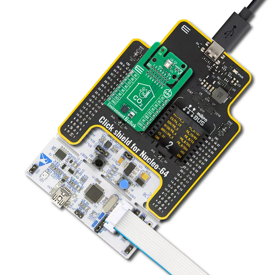
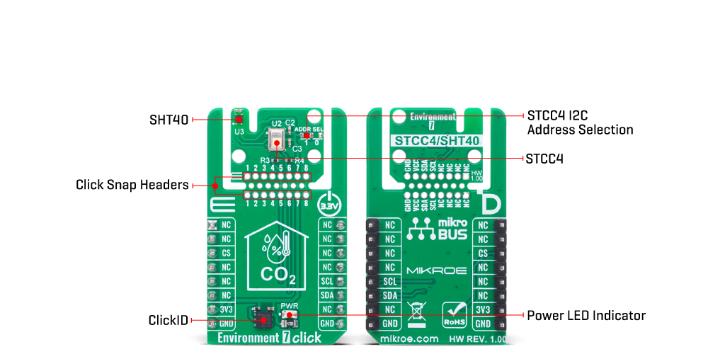
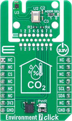
Environment 7 Click
Dev. board
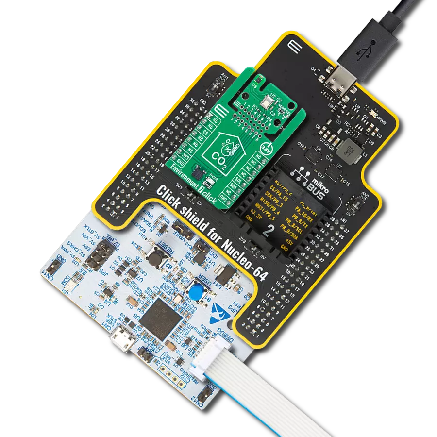
Nucleo 64 with STM32G474RE MCU
Compiler
NECTO Studio
MCU
STM32G474RE
Gain complete insight into your indoor environment and deliver reliable data for optimal air quality control
A
A
Hardware Overview
How does it work?
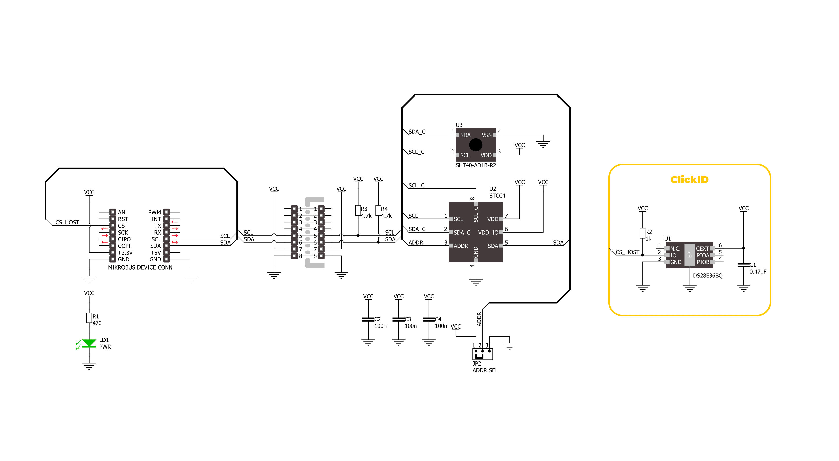
Environment 7 Click is a compact environmental monitoring solution that integrates two highly reliable sensors from Sensirion: the STCC4 CO₂ sensor and the SHT40 temperature and humidity sensor. Unlike standalone sensor boards, this Click board combines CO₂, temperature, and humidity measurements into a unified platform, enabling comprehensive environmental monitoring for indoor air quality applications. The STCC4 offers precise CO₂ concentration readings in the range of 400 to 5000 ppm with an accuracy of ±100ppm+10%, using advanced thermal conductivity sensing technology to ensure reliable performance. It is factory calibrated and optimized to deliver accurate results when paired with high-quality temperature and humidity data, making it ideal for use in air quality monitors, HVAC systems, and smart home devices. The SHT40 complements this setup with
its high-precision measurements of relative humidity (±1.8%RH) and temperature (±0.2°C), providing a full environmental profile that supports intelligent decision-making in demanding applications. It features ultra-low power consumption and robust performance in both standard and condensing environments, with a wide operating range and JEDEC qualification for durability. Together, these sensors allow Environment 7 Click to deliver synchronized environmental data through an I2C interface with selectable addresses. The result is a powerful, multi-sensor solution designed to ensure optimal indoor conditions, energy efficiency, and user comfort through precise, real-time monitoring of the most relevant air quality parameters. This Click board™ is designed in a unique format supporting the newly introduced MIKROE feature called "Click
Snap." Unlike the standardized version of Click boards, this feature allows the main sensor area to become movable by breaking the PCB, opening up many new possibilities for implementation. Thanks to the Snap feature, the STCC4 and STH40 can operate autonomously by accessing its signals directly on the pins marked 1-8. Additionally, the Snap part includes a specified and fixed screw hole position, enabling users to secure the Snap board in their desired location. This Click board™ can be operated only with a 3.3V logic voltage level. The board must perform appropriate logic voltage level conversion before using MCUs with different logic levels. It also comes equipped with a library containing functions and example code that can be used as a reference for further development.
Features overview
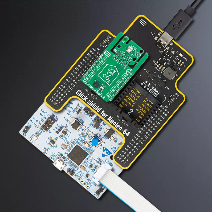
Development board
Nucleo-64 with STM32G474R MCU offers a cost-effective and adaptable platform for developers to explore new ideas and prototype their designs. This board harnesses the versatility of the STM32 microcontroller, enabling users to select the optimal balance of performance and power consumption for their projects. It accommodates the STM32 microcontroller in the LQFP64 package and includes essential components such as a user LED, which doubles as an ARDUINO® signal, alongside user and reset push-buttons, and a 32.768kHz crystal oscillator for precise timing operations. Designed with expansion and flexibility in mind, the Nucleo-64 board features an ARDUINO® Uno V3 expansion connector and ST morpho extension pin
headers, granting complete access to the STM32's I/Os for comprehensive project integration. Power supply options are adaptable, supporting ST-LINK USB VBUS or external power sources, ensuring adaptability in various development environments. The board also has an on-board ST-LINK debugger/programmer with USB re-enumeration capability, simplifying the programming and debugging process. Moreover, the board is designed to simplify advanced development with its external SMPS for efficient Vcore logic supply, support for USB Device full speed or USB SNK/UFP full speed, and built-in cryptographic features, enhancing both the power efficiency and security of projects. Additional connectivity is
provided through dedicated connectors for external SMPS experimentation, a USB connector for the ST-LINK, and a MIPI® debug connector, expanding the possibilities for hardware interfacing and experimentation. Developers will find extensive support through comprehensive free software libraries and examples, courtesy of the STM32Cube MCU Package. This, combined with compatibility with a wide array of Integrated Development Environments (IDEs), including IAR Embedded Workbench®, MDK-ARM, and STM32CubeIDE, ensures a smooth and efficient development experience, allowing users to fully leverage the capabilities of the Nucleo-64 board in their projects.

Microcontroller Overview
MCU Card / MCU

Architecture
ARM Cortex-M4
MCU Memory (KB)
512
Silicon Vendor
STMicroelectronics
Pin count
64
RAM (Bytes)
128k
You complete me!
Accessories
Click Shield for Nucleo-64 comes equipped with two proprietary mikroBUS™ sockets, allowing all the Click board™ devices to be interfaced with the STM32 Nucleo-64 board with no effort. This way, Mikroe allows its users to add any functionality from our ever-growing range of Click boards™, such as WiFi, GSM, GPS, Bluetooth, ZigBee, environmental sensors, LEDs, speech recognition, motor control, movement sensors, and many more. More than 1537 Click boards™, which can be stacked and integrated, are at your disposal. The STM32 Nucleo-64 boards are based on the microcontrollers in 64-pin packages, a 32-bit MCU with an ARM Cortex M4 processor operating at 84MHz, 512Kb Flash, and 96KB SRAM, divided into two regions where the top section represents the ST-Link/V2 debugger and programmer while the bottom section of the board is an actual development board. These boards are controlled and powered conveniently through a USB connection to program and efficiently debug the Nucleo-64 board out of the box, with an additional USB cable connected to the USB mini port on the board. Most of the STM32 microcontroller pins are brought to the IO pins on the left and right edge of the board, which are then connected to two existing mikroBUS™ sockets. This Click Shield also has several switches that perform functions such as selecting the logic levels of analog signals on mikroBUS™ sockets and selecting logic voltage levels of the mikroBUS™ sockets themselves. Besides, the user is offered the possibility of using any Click board™ with the help of existing bidirectional level-shifting voltage translators, regardless of whether the Click board™ operates at a 3.3V or 5V logic voltage level. Once you connect the STM32 Nucleo-64 board with our Click Shield for Nucleo-64, you can access hundreds of Click boards™, working with 3.3V or 5V logic voltage levels.

Used MCU Pins
mikroBUS™ mapper
Take a closer look
Click board™ Schematic
Step by step
Project assembly
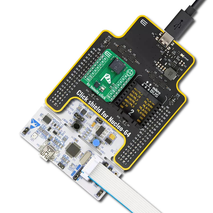
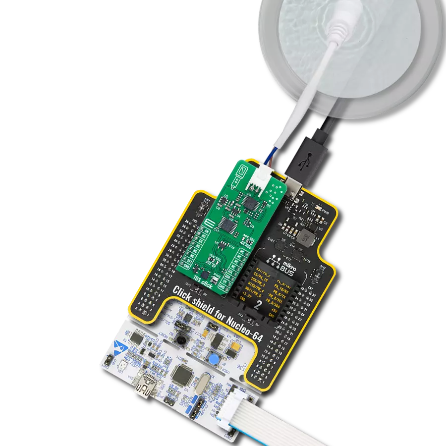
Start by selecting your development board and Click board™. Begin with the Nucleo 64 with STM32G474RE MCU as your development board.


Software Support
Library Description
Environment 7 Click demo application is developed using the NECTO Studio, ensuring compatibility with mikroSDK's open-source libraries and tools. Designed for plug-and-play implementation and testing, the demo is fully compatible with all development, starter, and mikromedia boards featuring a mikroBUS™ socket.
Example Description
This example demonstrates the use of the Environment 7 Click board, which provides temperature, humidity, and CO2 concentration measurements. The example initializes the device, reads sensor IDs, and continuously logs environmental data.
Key functions:
environment7_cfg_setup- This function initializes Click configuration structure to initial values.environment7_init- This function initializes all necessary pins and peripherals used for this Click board.environment7_read_id- This function reads the product and serial numbers of the STCC4 device.environment7_set_meas_mode- This function sets the measurement mode on the STCC4 device.environment7_read_meas- This function reads gas concentration, temperature, and relative humidity data from the STCC4 device.
Application Init
Initializes the logger, retrieves and logs the product and serial numbers, and starts the measurement in continuous mode with 1Hz sampling rate.
Application Task
Continuously reads and logs temperature (degC) and humidity (%RH), and CO2 concentration (ppm) from sensors.
Open Source
Code example
The complete application code and a ready-to-use project are available through the NECTO Studio Package Manager for direct installation in the NECTO Studio. The application code can also be found on the MIKROE GitHub account.
/*!
 * @file main.c
 * @brief Environment 7 Click example
 *
 * # Description
 * This example demonstrates the use of the Environment 7 Click board, which provides
 * temperature, humidity, and CO2 concentration measurements. The example initializes
 * the device, reads sensor IDs, and continuously logs environmental data.
 *
 * The demo application is composed of two sections:
 *
 * ## Application Init
 * Initializes the logger, retrieves and logs the product and serial numbers, and starts
 * the measurement in continuous mode with 1Hz sampling rate.
 *
 * ## Application Task
 * Continuously reads and logs temperature (degC) and humidity (%RH), and CO2 concentration (ppm)
 * from sensors.
 *
 * @author Stefan Filipovic
 *
 */

#include "board.h"
#include "log.h"
#include "environment7.h"

static environment7_t environment7;
static log_t logger;

void application_init ( void )
{
    log_cfg_t log_cfg;  /**< Logger config object. */
    environment7_cfg_t environment7_cfg;  /**< Click config object. */

    /**
     * Logger initialization.
     * Default baud rate: 115200
     * Default log level: LOG_LEVEL_DEBUG
     * @note If USB_UART_RX and USB_UART_TX
     * are defined as HAL_PIN_NC, you will
     * need to define them manually for log to work.
     * See @b LOG_MAP_USB_UART macro definition for detailed explanation.
     */
    LOG_MAP_USB_UART( log_cfg );
    log_init( &logger, &log_cfg );
    log_info( &logger, " Application Init " );

    // Click initialization.
    environment7_cfg_setup( &environment7_cfg );
    ENVIRONMENT7_MAP_MIKROBUS( environment7_cfg, MIKROBUS_1 );
    if ( I2C_MASTER_ERROR == environment7_init( &environment7, &environment7_cfg ) )
    {
        log_error( &logger, " Communication init." );
        for ( ; ; );
    }

    uint32_t prod_num = 0;
    uint32_t serial_msb = 0;
    uint32_t serial_lsb = 0;
    if ( ENVIRONMENT7_OK != environment7_read_id ( &environment7, &prod_num, &serial_msb, &serial_lsb ) )
    {
        log_error( &logger, " Check communication." );
        for ( ; ; );
    }
    log_printf ( &logger, " Product number: 0x%.8LX\r\n", prod_num );
    log_printf ( &logger, " Serial number: 0x%.8LX%.8LX\r\n", serial_msb, serial_lsb );

    if ( ENVIRONMENT7_OK == environment7_set_meas_mode ( &environment7, ENVIRONMENT7_MEAS_MODE_START_CONTINUOUS ) )
    {
        log_printf ( &logger, " Continuous measurement started (1 Hz output)\r\n" );
    }

    log_info( &logger, " Application Task " );
}

void application_task ( void )
{
    float temperature = 0;
    float humidity = 0;
    uint16_t co2_concentration = 0;

    if ( ENVIRONMENT7_OK == environment7_read_meas ( &environment7, &co2_concentration, &temperature, &humidity ) )
    {
        log_printf ( &logger, " Temperature: %.2f degC\r\n", temperature );
        log_printf ( &logger, " Humidity: %.2f %%RH\r\n", humidity );
        log_printf ( &logger, " CO2: %u ppm\r\n\n", co2_concentration );
        Delay_ms ( 1000 );
    }
}

int main ( void )
{
    /* Do not remove this line or clock might not be set correctly. */
    #ifdef PREINIT_SUPPORTED
    preinit();
    #endif

    application_init( );

    for ( ; ; )
    {
        application_task( );
    }

    return 0;
}

// ------------------------------------------------------------------------ END
Additional Support
Resources
Category:Environmental