Drive 2-phase bipolar stepper motors with TB67S559FTG and STM32G071RB
High-current bipolar stepper motor driver with resistor-less current sensing and microstepping control
Published Oct 08, 2025
Click board™
Stepper 28 Click
Dev. board
Nucleo 64 with STM32G071RB MCU
Compiler
NECTO Studio
MCU
STM32G071RB
Achieve reliable stepper motor performance with up to 3A output and advanced current sensing
A
A
Hardware Overview
How does it work?
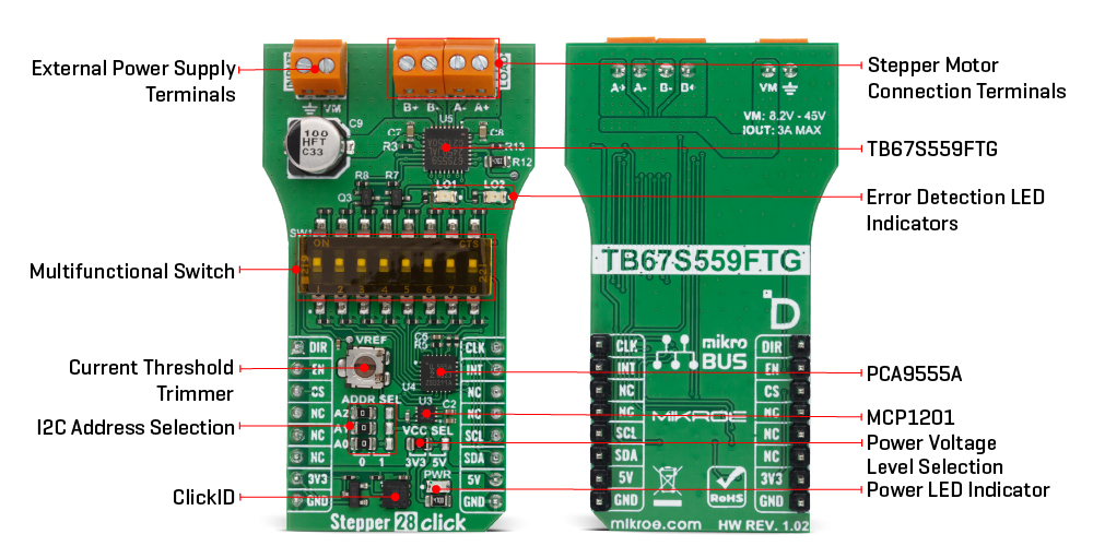
Stepper 28 Click is based on the TB67S559FTG, a PWM chopper-type 2-phase bipolar stepping motor driver IC from Toshiba Semiconductor designed using the BiCD process, integrating DMOSFETs as output power transistors. It supports motor drive with a single power supply ranging from 8.2V to 44V and delivers up to 2.7A maximum current output with a built-in regulator for internal IC supply. The TB67S559FTG incorporates Advanced Current Detect System (ACDS) technology, eliminating the need for external current detection resistors, and Advanced Dynamic Mixed Decay (ADMD) functionality, and protections like over-temperature, over-current, and under-voltage lockout. It also supports full-step to 1/32 step resolutions for less motor noise and smoother control, with a built-in mixed decay mode which helps to stabilize the current waveforms. Thanks to the micro steps capability the TB67S559FTG supports, motor noise can be significantly reduced with smoother operation and more precise control. It is suited for driving 2-phase bipolar stepper motors in industrial automation, office equipment, and robotics applications. The current value is set by the reference voltage value obtained by the MCP1501, a high-precision voltage regulator. Also, the current threshold point of the TB67S589FTG, alongside MCP1501, can be set manually using an onboard trimmer labeled VR. The control of the Stepper 28 Click is managed through specific pins on the mikroBUS™ socket: The CLK clock signal, routed to the default PWM position, advances the motor's current step and electrical angle with each rising edge. The Enable pin, EN pin, controls the
activation state of the output A and B stepping motor drive channels. Additionally, the DIR pin determines the rotation direction of the stepping motor, with a HIGH logic level indicating forward rotation and a LOW logic level indicating reverse rotation. Due to the limited number of control pins on the mikroBUS™ for managing the TB67S559FTG, the Stepper 28 Click also incorporates the PCA9555A port expander. This port expander, interfacing via the I2C interface, provides additional control over the TB67S559FTG and its functions. One of the key functions enabled through this port expander is the Decay mode. The selectable mixed decay function allows to switch between four decay modes MIXED, SLOW, FAST, and ADMD (Advanced Dynamic Mixed Decay technology from Toshiba). This optimization enhances the performance and efficiency of the stepping motor. Additionally, the Torque mode pins set the motor's torque by adjusting the logical levels of both IC’s TRQx pins. It is possible to set the torque to 100%, 75%, 50%, or 25% without changing the reference voltage level of the current regulator . The RST pin resets the electrical angle in the internal counter to an initial position. Furthermore, the MO pin indicates the achievement of the initial electrical angle position. Besides these functions, the port expander also controls the DMODE pins, which set the step resolution to full, half-step, quarter-step, 1/8, 1/16, or 1/32. The Sleep mode function allows switching between power-saving mode and normal operation mode. By setting the Sleep mode and then returning to the normal operation mode, it is possible to recover
from the forced OFF-state caused by the overheating or over-current detection circuit operation. Alternatively these functions can also be controlled via a multifunctional switch, where selecting a particular switch position (1 for Sleep Mode; 2, 3 for Torque Control; 4,5 for Decay Mode Control; 6,7,8 for Step Resolution Setting) allows for easy and efficient management of the board's operations. The board also includes two LED error signalling indicators: a LO1 red LED is active when overcurrent or overtemperature occurs, while LO2 is only active when overtemperature occurs (to differentiate the LO1 general error signal). The PCA9555A also allows choosing the least significant bit (LSB) of its I2C address by positioning SMD jumpers labeled as ADDR SEL to an appropriate position marked as 0 and 1, alongside its interrupt feature routed to the INT pin of the mikroBUS™ socket. The INT pin signals the host MCU in cases such as overcurrent and overtemperature conditions (in addition to LED indicators for visual detection of these states), as well as the MO pin status that indicates the achievement of the initial electrical angle position. This Click board™ can operate with either 3.3V or 5V logic voltage levels selected via the VCC SEL jumper. This way, both 3.3V and 5V capable MCUs can use the communication lines properly. Also, this Click board™ comes equipped with a library containing easy-to-use functions and an example code that can be used as a reference for further development.
Features overview
Development board
Nucleo-64 with STM32G071RB MCU offers a cost-effective and adaptable platform for developers to explore new ideas and prototype their designs. This board harnesses the versatility of the STM32 microcontroller, enabling users to select the optimal balance of performance and power consumption for their projects. It accommodates the STM32 microcontroller in the LQFP64 package and includes essential components such as a user LED, which doubles as an ARDUINO® signal, alongside user and reset push-buttons, and a 32.768kHz crystal oscillator for precise timing operations. Designed with expansion and flexibility in mind, the Nucleo-64 board features an ARDUINO® Uno V3 expansion connector and ST morpho extension pin
headers, granting complete access to the STM32's I/Os for comprehensive project integration. Power supply options are adaptable, supporting ST-LINK USB VBUS or external power sources, ensuring adaptability in various development environments. The board also has an on-board ST-LINK debugger/programmer with USB re-enumeration capability, simplifying the programming and debugging process. Moreover, the board is designed to simplify advanced development with its external SMPS for efficient Vcore logic supply, support for USB Device full speed or USB SNK/UFP full speed, and built-in cryptographic features, enhancing both the power efficiency and security of projects. Additional connectivity is
provided through dedicated connectors for external SMPS experimentation, a USB connector for the ST-LINK, and a MIPI® debug connector, expanding the possibilities for hardware interfacing and experimentation. Developers will find extensive support through comprehensive free software libraries and examples, courtesy of the STM32Cube MCU Package. This, combined with compatibility with a wide array of Integrated Development Environments (IDEs), including IAR Embedded Workbench®, MDK-ARM, and STM32CubeIDE, ensures a smooth and efficient development experience, allowing users to fully leverage the capabilities of the Nucleo-64 board in their projects.

Microcontroller Overview
MCU Card / MCU

Architecture
ARM Cortex-M0
MCU Memory (KB)
128
Silicon Vendor
STMicroelectronics
Pin count
64
RAM (Bytes)
36864
You complete me!
Accessories
Click Shield for Nucleo-64 comes equipped with two proprietary mikroBUS™ sockets, allowing all the Click board™ devices to be interfaced with the STM32 Nucleo-64 board with no effort. This way, Mikroe allows its users to add any functionality from our ever-growing range of Click boards™, such as WiFi, GSM, GPS, Bluetooth, ZigBee, environmental sensors, LEDs, speech recognition, motor control, movement sensors, and many more. More than 1537 Click boards™, which can be stacked and integrated, are at your disposal. The STM32 Nucleo-64 boards are based on the microcontrollers in 64-pin packages, a 32-bit MCU with an ARM Cortex M4 processor operating at 84MHz, 512Kb Flash, and 96KB SRAM, divided into two regions where the top section represents the ST-Link/V2 debugger and programmer while the bottom section of the board is an actual development board. These boards are controlled and powered conveniently through a USB connection to program and efficiently debug the Nucleo-64 board out of the box, with an additional USB cable connected to the USB mini port on the board. Most of the STM32 microcontroller pins are brought to the IO pins on the left and right edge of the board, which are then connected to two existing mikroBUS™ sockets. This Click Shield also has several switches that perform functions such as selecting the logic levels of analog signals on mikroBUS™ sockets and selecting logic voltage levels of the mikroBUS™ sockets themselves. Besides, the user is offered the possibility of using any Click board™ with the help of existing bidirectional level-shifting voltage translators, regardless of whether the Click board™ operates at a 3.3V or 5V logic voltage level. Once you connect the STM32 Nucleo-64 board with our Click Shield for Nucleo-64, you can access hundreds of Click boards™, working with 3.3V or 5V logic voltage levels.

Used MCU Pins
mikroBUS™ mapper
Take a closer look
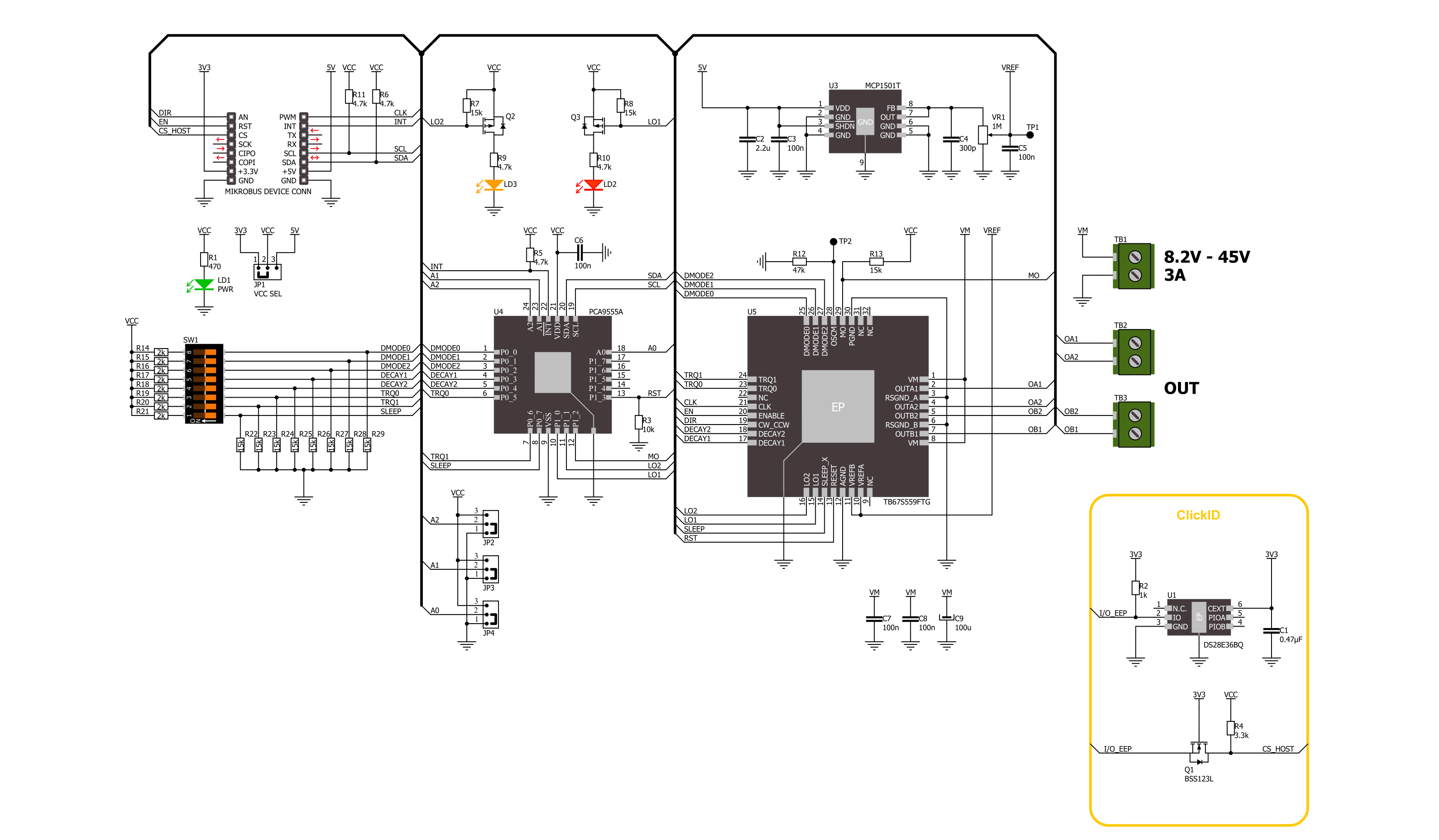
Click board™ Schematic
Step by step
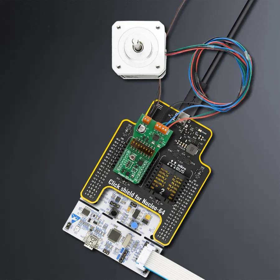
Project assembly
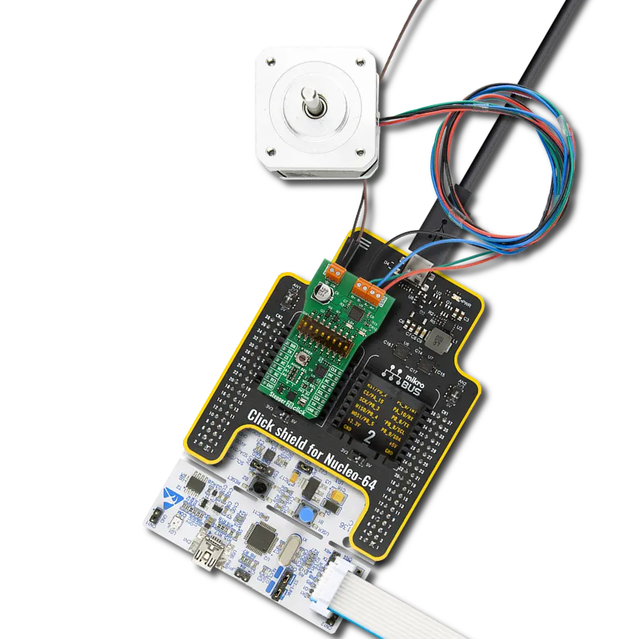
Start by selecting your development board and Click board™. Begin with the Nucleo 64 with STM32G071RB MCU as your development board.


Track your results in real time
Application Output
1. Application Output - In Debug mode, the 'Application Output' window enables real-time data monitoring, offering direct insight into execution results. Ensure proper data display by configuring the environment correctly using the provided tutorial.

2. UART Terminal - Use the UART Terminal to monitor data transmission via a USB to UART converter, allowing direct communication between the Click board™ and your development system. Configure the baud rate and other serial settings according to your project's requirements to ensure proper functionality. For step-by-step setup instructions, refer to the provided tutorial.

3. Plot Output - The Plot feature offers a powerful way to visualize real-time sensor data, enabling trend analysis, debugging, and comparison of multiple data points. To set it up correctly, follow the provided tutorial, which includes a step-by-step example of using the Plot feature to display Click board™ readings. To use the Plot feature in your code, use the function: plot(*insert_graph_name*, variable_name);. This is a general format, and it is up to the user to replace 'insert_graph_name' with the actual graph name and 'variable_name' with the parameter to be displayed.

Software Support
Library Description
Stepper 28 Click demo application is developed using the NECTO Studio, ensuring compatibility with mikroSDK's open-source libraries and tools. Designed for plug-and-play implementation and testing, the demo is fully compatible with all development, starter, and mikromedia boards featuring a mikroBUS™ socket.
Example Description
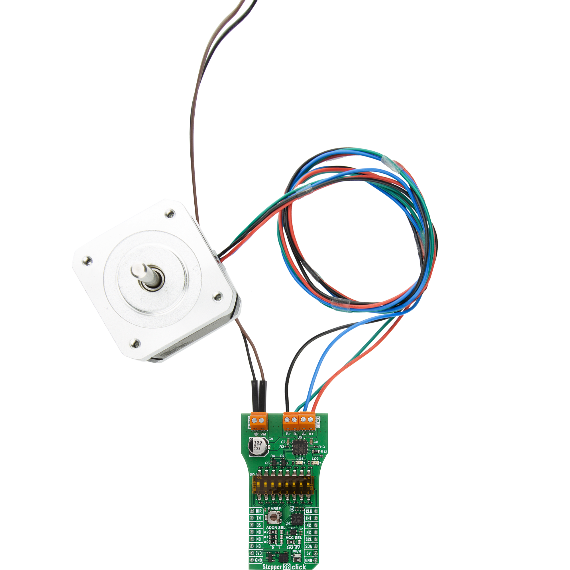
This example demonstrates the use of the Stepper 28 Click board by driving the motor in both directions for a desired number of steps.
Key functions:
stepper28_cfg_setup- This function initializes Click configuration structure to initial values.stepper28_init- This function initializes all necessary pins and peripherals used for this Click board.stepper28_default_cfg- This function executes a default configuration of Stepper 28 Click board.stepper28_set_direction- This function sets the motor direction by setting the DIR pin logic state.stepper28_set_step_mode- This function sets the step mode resolution settings.stepper28_drive_motor- This function drives the motor for the specific number of steps at the selected speed.
Application Init
Initializes the driver and performs the Click default configuration.
Application Task
Drives the motor clockwise for 200 full steps and then counter-clockwise for 200 half steps and 400 quarter steps with a 1 second delay on driving mode change. All data is being logged on the USB UART where you can track the program flow.
Open Source
Code example
The complete application code and a ready-to-use project are available through the NECTO Studio Package Manager for direct installation in the NECTO Studio. The application code can also be found on the MIKROE GitHub account.
/*!
 * @file main.c
 * @brief Stepper 28 Click example
 *
 * # Description
 * This example demonstrates the use of the Stepper 28 Click board by driving the
 * motor in both directions for a desired number of steps.
 *
 * The demo application is composed of two sections :
 *
 * ## Application Init
 * Initializes the driver and performs the Click default configuration.
 *
 * ## Application Task
 * Drives the motor clockwise for 200 full steps and then counter-clockwise for 200 half
 * steps and 400 quarter steps with a 1 second delay on driving mode change. All data is
 * being logged on the USB UART where you can track the program flow.
 *
 * @author Stefan Filipovic
 *
 */

#include "board.h"
#include "log.h"
#include "stepper28.h"

static stepper28_t stepper28;
static log_t logger;

void application_init ( void )
{
    log_cfg_t log_cfg;  /**< Logger config object. */
    stepper28_cfg_t stepper28_cfg;  /**< Click config object. */

    /**
     * Logger initialization.
     * Default baud rate: 115200
     * Default log level: LOG_LEVEL_DEBUG
     * @note If USB_UART_RX and USB_UART_TX
     * are defined as HAL_PIN_NC, you will
     * need to define them manually for log to work.
     * See @b LOG_MAP_USB_UART macro definition for detailed explanation.
     */
    LOG_MAP_USB_UART( log_cfg );
    log_init( &logger, &log_cfg );
    log_info( &logger, " Application Init " );

    // Click initialization.
    stepper28_cfg_setup( &stepper28_cfg );
    STEPPER28_MAP_MIKROBUS( stepper28_cfg, MIKROBUS_1 );
    if ( I2C_MASTER_ERROR == stepper28_init( &stepper28, &stepper28_cfg ) )
    {
        log_error( &logger, " Communication init." );
        for ( ; ; );
    }

    if ( STEPPER28_ERROR == stepper28_default_cfg ( &stepper28 ) )
    {
        log_error( &logger, " Default configuration." );
        for ( ; ; );
    }

    log_info( &logger, " Application Task " );
}

void application_task ( void )
{
    log_printf ( &logger, " Move 200 full steps clockwise, speed: slow\r\n\n" );
    stepper28_set_direction ( &stepper28, STEPPER28_DIR_CW );
    stepper28_set_step_mode ( &stepper28, STEPPER28_MODE_FULL_STEP );
    stepper28_drive_motor ( &stepper28, 200, STEPPER28_SPEED_SLOW );
    Delay_ms ( 1000 );

    log_printf ( &logger, " Move 200 half steps counter-clockwise, speed: medium\r\n\n" );
    stepper28_set_direction ( &stepper28, STEPPER28_DIR_CCW );
    stepper28_set_step_mode ( &stepper28, STEPPER28_MODE_HALF_STEP_TYPE_A );
    stepper28_drive_motor ( &stepper28, 200, STEPPER28_SPEED_MEDIUM );
    Delay_ms ( 1000 );

    log_printf ( &logger, " Move 400 quarter steps counter-clockwise, speed: fast\r\n\n" );
    stepper28_set_direction ( &stepper28, STEPPER28_DIR_CCW );
    stepper28_set_step_mode ( &stepper28, STEPPER28_MODE_QUARTER_STEP );
    stepper28_drive_motor ( &stepper28, 400, STEPPER28_SPEED_FAST );
    Delay_ms ( 1000 );
}

int main ( void )
{
    /* Do not remove this line or clock might not be set correctly. */
    #ifdef PREINIT_SUPPORTED
    preinit();
    #endif

    application_init( );

    for ( ; ; )
    {
        application_task( );
    }

    return 0;
}

// ------------------------------------------------------------------------ END
Additional Support
Resources
Category:Stepper