Add precise two-axis joystick control with tactile feedback using the THB001P, VZ43FC1B5640007L, and ATmega328
Joystick control with haptic feedback for intuitive user interfaces
Published Oct 20, 2025
Click board™
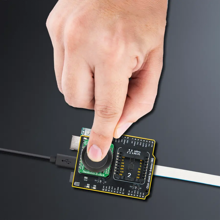
Thumbstick 2 Click
Dev. board
Arduino UNO Rev3
Compiler
NECTO Studio
MCU
ATmega328
Two-axis joystick control with an integrated push button and haptic feedback perfect for intuitive user interfaces
A
A
Hardware Overview
How does it work?
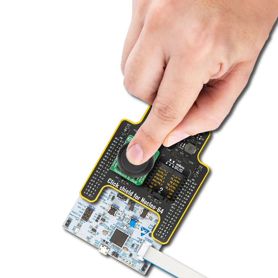
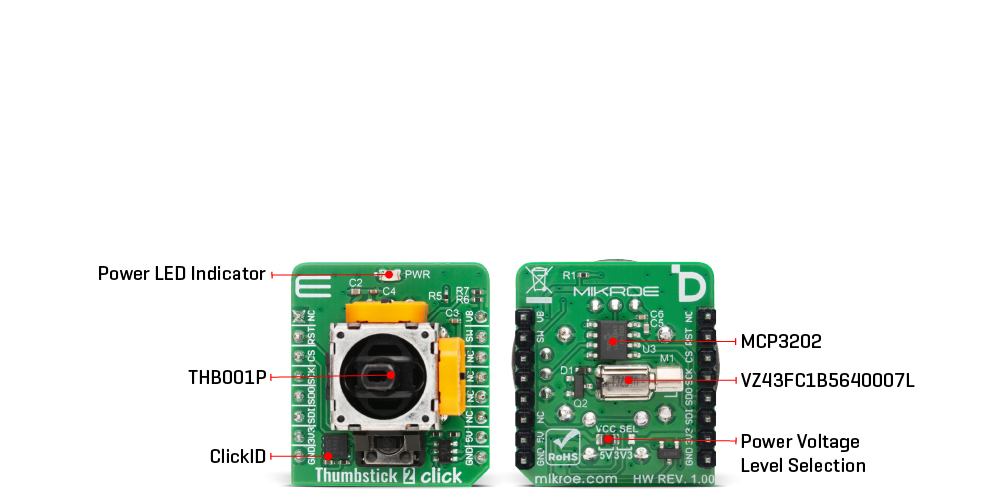
Thumbstick 2 Click is based on the THB001P, a high-quality two-axis joystick with an integrated push button from C&K Components, combined with additional circuitry to deliver advanced input and haptic feedback capabilities for embedded applications. The joystick provides smooth and precise motion control across both the X and Y axes, while its angular displacement and positional data are converted into digital form through the MCP3202, a 12-bit A/D converter from Microchip that communicates via an SPI serial interface. This allows reliable acquisition of raw analog values that represent the joystick’s movements, ensuring
accurate control in a wide range of applications including human–machine interfaces, handheld control units, industrial equipment, assistive devices, and gaming controllers where precise positioning and tactile confirmation are essential. In addition to directional input, the built-in push button expands the input functionality by enabling discrete command execution when pressed, and this button is also linked to control the onboard vibration motor. The vibration motor used on the back of the board, the VZ43FC1B5640007L, delivers strong tactile feedback with a force of 0.91G and operates at a rated speed of 10,000 rpm, creating a
responsive haptic signal that can be used to enhance user interaction in real time. Its operation is managed through the VB pin using PWM control, making it possible to fine-tune vibration intensity and duration according to application requirements. This Click board™ can operate with either 3.3V or 5V logic voltage levels selected via the VCC SEL jumper. This way, both 3.3V and 5V capable MCUs can use the communication lines properly. Also, this Click board™ comes equipped with a library containing easy-to-use functions and an example code that can be used as a reference for further development.
Features overview
Development board
Arduino UNO is a versatile microcontroller board built around the ATmega328P chip. It offers extensive connectivity options for various projects, featuring 14 digital input/output pins, six of which are PWM-capable, along with six analog inputs. Its core components include a 16MHz ceramic resonator, a USB connection, a power jack, an
ICSP header, and a reset button, providing everything necessary to power and program the board. The Uno is ready to go, whether connected to a computer via USB or powered by an AC-to-DC adapter or battery. As the first USB Arduino board, it serves as the benchmark for the Arduino platform, with "Uno" symbolizing its status as the
first in a series. This name choice, meaning "one" in Italian, commemorates the launch of Arduino Software (IDE) 1.0. Initially introduced alongside version 1.0 of the Arduino Software (IDE), the Uno has since become the foundational model for subsequent Arduino releases, embodying the platform's evolution.

Microcontroller Overview
MCU Card / MCU

Architecture
AVR
MCU Memory (KB)
32
Silicon Vendor
Microchip
Pin count
32
RAM (Bytes)
2048
You complete me!
Accessories
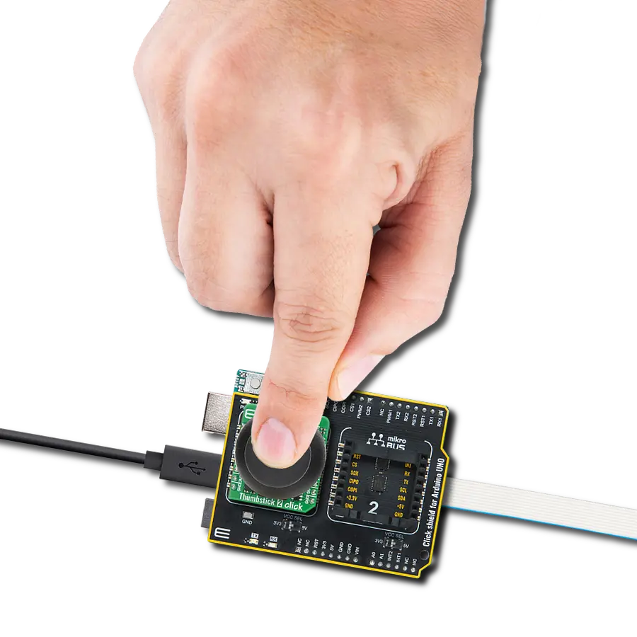
Click Shield for Arduino UNO has two proprietary mikroBUS™ sockets, allowing all the Click board™ devices to be interfaced with the Arduino UNO board without effort. The Arduino Uno, a microcontroller board based on the ATmega328P, provides an affordable and flexible way for users to try out new concepts and build prototypes with the ATmega328P microcontroller from various combinations of performance, power consumption, and features. The Arduino Uno has 14 digital input/output pins (of which six can be used as PWM outputs), six analog inputs, a 16 MHz ceramic resonator (CSTCE16M0V53-R0), a USB connection, a power jack, an ICSP header, and reset button. Most of the ATmega328P microcontroller pins are brought to the IO pins on the left and right edge of the board, which are then connected to two existing mikroBUS™ sockets. This Click Shield also has several switches that perform functions such as selecting the logic levels of analog signals on mikroBUS™ sockets and selecting logic voltage levels of the mikroBUS™ sockets themselves. Besides, the user is offered the possibility of using any Click board™ with the help of existing bidirectional level-shifting voltage translators, regardless of whether the Click board™ operates at a 3.3V or 5V logic voltage level. Once you connect the Arduino UNO board with our Click Shield for Arduino UNO, you can access hundreds of Click boards™, working with 3.3V or 5V logic voltage levels.

Used MCU Pins
mikroBUS™ mapper
Take a closer look
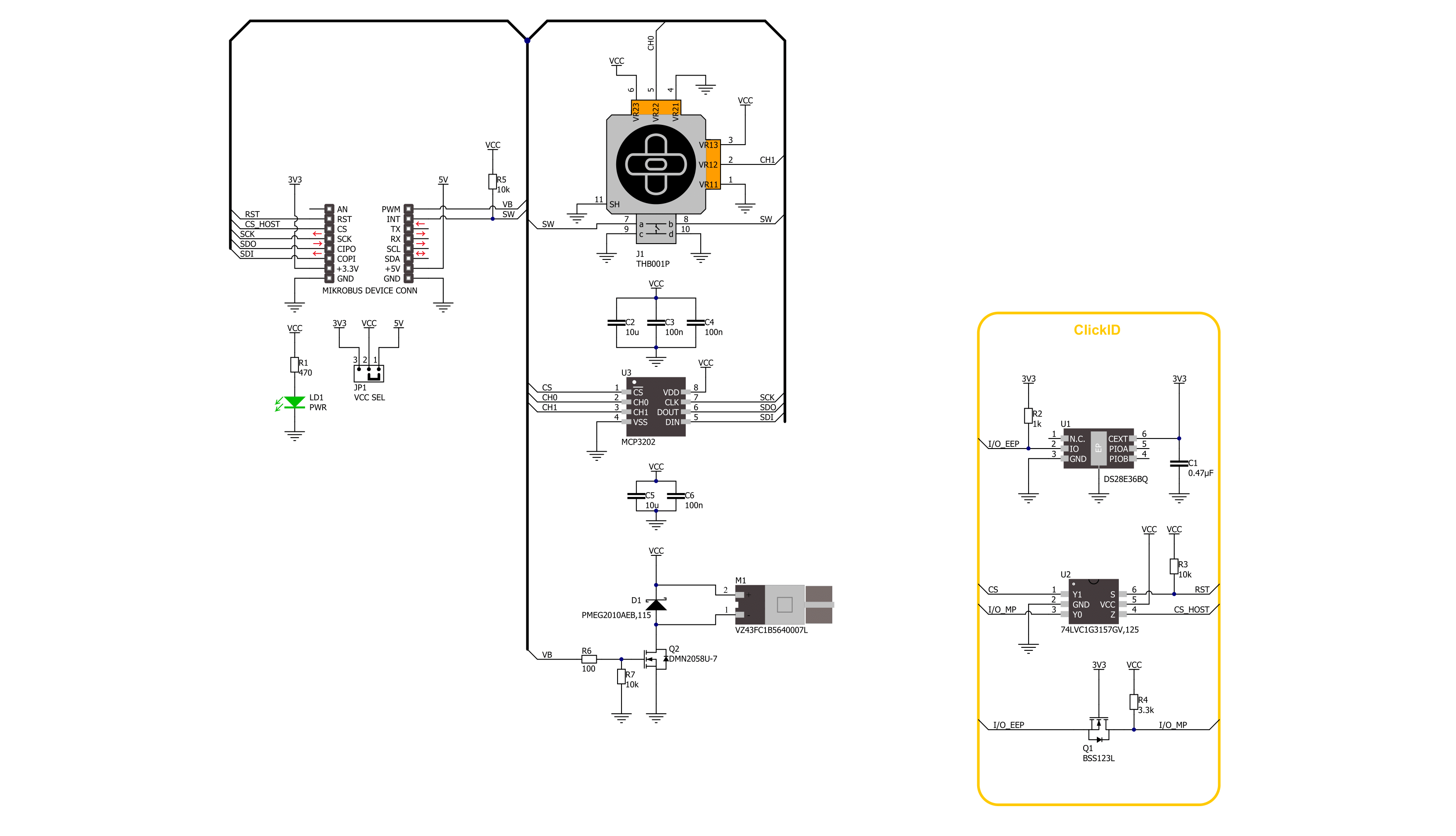
Click board™ Schematic
Step by step
Project assembly

Start by selecting your development board and Click board™. Begin with the Arduino UNO Rev3 as your development board.


Track your results in real time
Application Output
1. Application Output - In Debug mode, the 'Application Output' window enables real-time data monitoring, offering direct insight into execution results. Ensure proper data display by configuring the environment correctly using the provided tutorial.

2. UART Terminal - Use the UART Terminal to monitor data transmission via a USB to UART converter, allowing direct communication between the Click board™ and your development system. Configure the baud rate and other serial settings according to your project's requirements to ensure proper functionality. For step-by-step setup instructions, refer to the provided tutorial.

3. Plot Output - The Plot feature offers a powerful way to visualize real-time sensor data, enabling trend analysis, debugging, and comparison of multiple data points. To set it up correctly, follow the provided tutorial, which includes a step-by-step example of using the Plot feature to display Click board™ readings. To use the Plot feature in your code, use the function: plot(*insert_graph_name*, variable_name);. This is a general format, and it is up to the user to replace 'insert_graph_name' with the actual graph name and 'variable_name' with the parameter to be displayed.

Software Support
Library Description
Thumbstick 2 Click demo application is developed using the NECTO Studio, ensuring compatibility with mikroSDK's open-source libraries and tools. Designed for plug-and-play implementation and testing, the demo is fully compatible with all development, starter, and mikromedia boards featuring a mikroBUS™ socket.
Example Description
This example demonstrates the use of the Thumbstick 2 Click board which features a 2-axis joystick with push button and vibration feedback. The joystick's angle and position are calculated based on raw ADC values, while the push button status controls the vibration motor through PWM output.
Key functions:
thumbstick2_cfg_setup- This function initializes Click configuration structure to initial values.thumbstick2_init- This function initializes all necessary pins and peripherals used for this Click board.thumbstick2_read_raw_adc- This function reads the raw ADC for X and Y axis by using SPI serial interface.thumbstick2_get_angle- This function calculates and returns joystick angle in degrees from raw ADC values for X and Y axis.thumbstick2_get_position- This function calculates and returns joystick position flag from raw ADC values for X and Y axis.
Application Init
Initializes the logger and the Click driver.
Application Task
Continuously reads the raw ADC values from the joystick axes, calculates the joystick's position and angle, and logs the results. It also checks the state of the joystick push button and activates vibration feedback accordingly.
Open Source
Code example
The complete application code and a ready-to-use project are available through the NECTO Studio Package Manager for direct installation in the NECTO Studio. The application code can also be found on the MIKROE GitHub account.
/*!
 * @file main.c
 * @brief Thumbstick 2 Click example
 *
 * # Description
 * This example demonstrates the use of the Thumbstick 2 Click board which
 * features a 2-axis joystick with push button and vibration feedback.
 * The joystick's angle and position are calculated based on raw ADC values,
 * while the push button status controls the vibration motor through PWM output.
 *
 * The demo application is composed of two sections :
 *
 * ## Application Init
 * Initializes the logger and the Click driver.
 *
 * ## Application Task
 * Continuously reads the raw ADC values from the joystick axes, calculates the
 * joystick's position and angle, and logs the results. It also checks the state
 * of the joystick push button and activates vibration feedback accordingly.
 *
 * @author Stefan Filipovic
 *
 */

#include "board.h"
#include "log.h"
#include "thumbstick2.h"

static thumbstick2_t thumbstick2;
static log_t logger;

void application_init ( void )
{
    log_cfg_t log_cfg;  /**< Logger config object. */
    thumbstick2_cfg_t thumbstick2_cfg;  /**< Click config object. */

    /**
     * Logger initialization.
     * Default baud rate: 115200
     * Default log level: LOG_LEVEL_DEBUG
     * @note If USB_UART_RX and USB_UART_TX
     * are defined as HAL_PIN_NC, you will
     * need to define them manually for log to work.
     * See @b LOG_MAP_USB_UART macro definition for detailed explanation.
     */
    LOG_MAP_USB_UART( log_cfg );
    log_init( &logger, &log_cfg );
    log_info( &logger, " Application Init " );

    // Click initialization.
    thumbstick2_cfg_setup( &thumbstick2_cfg );
    THUMBSTICK2_MAP_MIKROBUS( thumbstick2_cfg, MIKROBUS_1 );
    if ( THUMBSTICK2_OK != thumbstick2_init( &thumbstick2, &thumbstick2_cfg ) )
    {
        log_error( &logger, " Communication init." );
        for ( ; ; );
    }

    log_info( &logger, " Application Task " );
}

void application_task ( void )
{
    float angle = 0;
    uint16_t raw_x = 0;
    uint16_t raw_y = 0;
    uint8_t position = 0;
    if ( THUMBSTICK2_OK == thumbstick2_read_raw_adc ( &thumbstick2, &raw_x, &raw_y ) )
    {
        angle = thumbstick2_get_angle ( raw_x, raw_y );
        position = thumbstick2_get_position ( raw_x, raw_y );
        log_printf ( &logger, " RAW X: %u\r\n RAW Y: %u\r\n", raw_x, raw_y );
        log_printf ( &logger, " Joystick angle: %.1f degrees\r\n", angle );
        log_printf ( &logger, " Joystick position: " );
        switch ( position )
        {
            case THUMBSTICK2_POSITION_NEUTRAL:
            {
                log_printf ( &logger, "NEUTRAL" );
                break;
            }
            case THUMBSTICK2_POSITION_UP:
            {
                log_printf ( &logger, "UP" );
                break;
            }
            case THUMBSTICK2_POSITION_UPPER_LEFT:
            {
                log_printf ( &logger, "UPPER-LEFT" );
                break;
            }
            case THUMBSTICK2_POSITION_LEFT:
            {
                log_printf ( &logger, "LEFT" );
                break;
            }
            case THUMBSTICK2_POSITION_LOWER_LEFT:
            {
                log_printf ( &logger, "LOWER-LEFT" );
                break;
            }
            case THUMBSTICK2_POSITION_DOWN:
            {
                log_printf ( &logger, "DOWN" );
                break;
            }
            case THUMBSTICK2_POSITION_LOWER_RIGHT:
            {
                log_printf ( &logger, "LOWER-RIGHT" );
                break;
            }
            case THUMBSTICK2_POSITION_RIGHT:
            {
                log_printf ( &logger, "RIGHT" );
                break;
            }
            case THUMBSTICK2_POSITION_UPPER_RIGHT:
            {
                log_printf ( &logger, "UPPER-RIGHT" );
                break;
            }
            default:
            {
                log_printf ( &logger, "UNKNOWN" );
                break;
            }
        }
        log_printf ( &logger, "\r\n" );
        if ( thumbstick2_get_sw_pin ( &thumbstick2 ) )
        {
            log_printf ( &logger, " Button: Idle\r\n" );
            log_printf ( &logger, " Vibro: Idle\r\n\n" );
            thumbstick2_set_duty_cycle ( &thumbstick2, THUMBSTICK2_PWM_MIN_DUTY );
        }
        else
        {
            log_printf ( &logger, " Button: Active\r\n" );
            log_printf ( &logger, " Vibro: Active\r\n\n" );
            thumbstick2_set_duty_cycle ( &thumbstick2, THUMBSTICK2_PWM_MAX_DUTY );
        }
        Delay_ms ( 100 );
    }
}

int main ( void )
{
    /* Do not remove this line or clock might not be set correctly. */
    #ifdef PREINIT_SUPPORTED
    preinit();
    #endif

    application_init( );

    for ( ; ; )
    {
        application_task( );
    }

    return 0;
}

// ------------------------------------------------------------------------ END
Additional Support
Resources
Category:Pushbutton/Switches