Measure distances across 8x8 configurable zones for detailed spatial mapping with VL53L8CH and PIC32MX470F512H
Time-of-Flight sensing solution for AI apps with a wide 65° diagonal FoV

Published Feb 13, 2025
Click board™
LightRanger 12 Click
Dev. board
6LoWPAN clicker
Compiler
NECTO Studio
MCU
PIC32MX470F512H
Achieve precise distance measurement and spatial mapping with multizone ToF technology
A
A
Hardware Overview
How does it work?
LightRanger 12 Click is based on the VL53L8CH, an 8x8 multizone Time-of-Flight (ToF) sensor from STMicroelectronics, designed for AI applications with exceptional performance under ambient light conditions. This sensor offers a wide 65° diagonal field of view (45° x 45° square), making it ideal for precise distance measurement and spatial mapping applications. It introduces a Compact and Normalized Histogram (CNH) data output format, specifically made for artificial intelligence applications that demand multizone raw data from a high-performance optical sensor, including AI-driven robotics, smart appliances like coffee machines and beverage dispensers, smart home solutions, and advanced recognition systems. The VL53L8CH integrates a powerful new-generation Vertical-Cavity Surface-Emitting Laser (VCSEL) and two advanced metasurface lenses, enhancing its optical capabilities. The VCSEL emits an invisible 940 nm IR light that is Class 1 certified, ensuring eye safety while maintaining high performance. It also provides unparalleled flexibility by allowing users to configure up to 64 zones (8x8 grid), adjust histogram resolution to 128 bins, and define bin widths. Each zone's infrared signal is transmitted to the host as raw histogram data, complementing the standard ToF sensor outputs, such as ranging distances up to 400 cm, signal
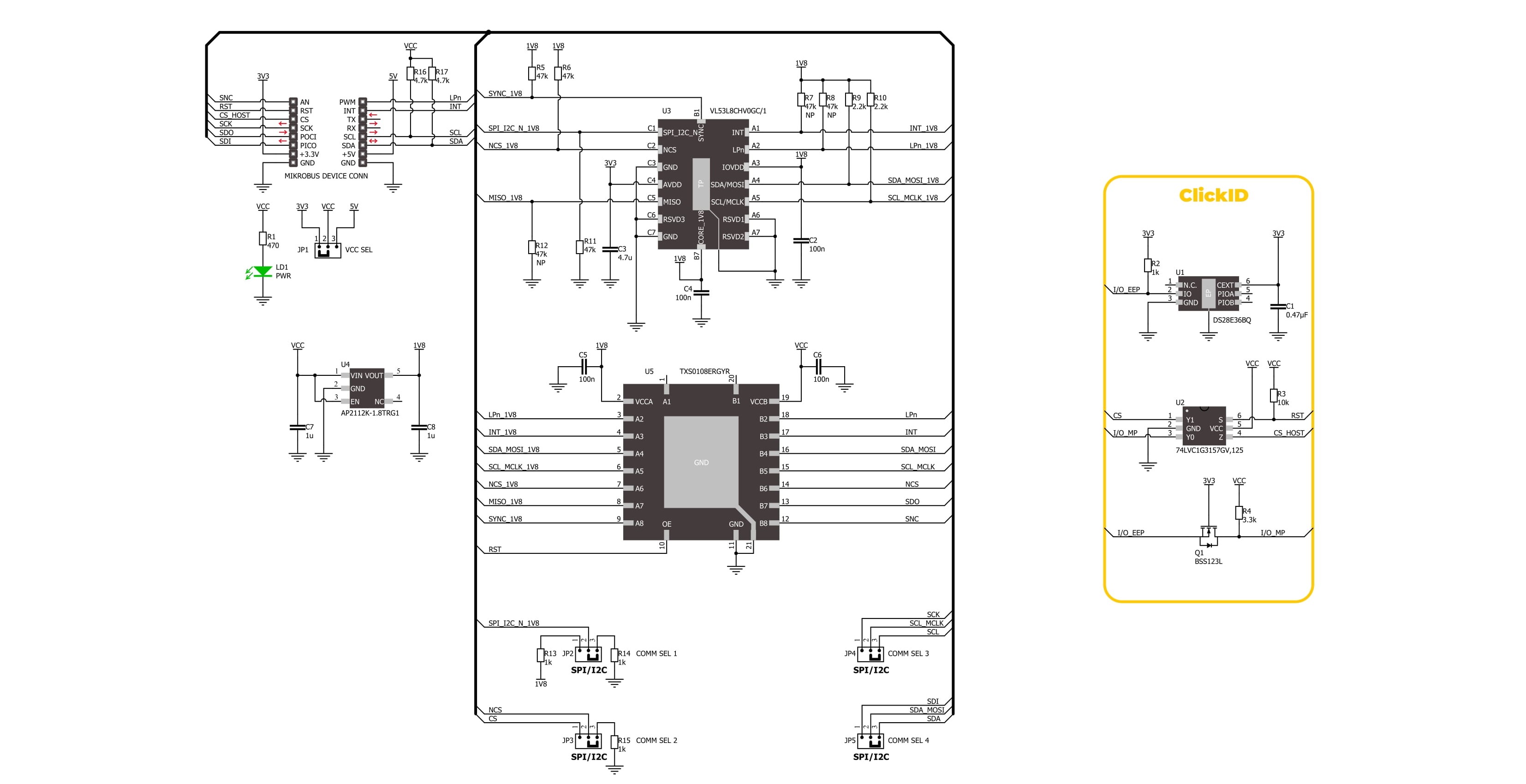
levels, and reflectance. By combining raw histogram data with traditional ranging capabilities, the VL53L8CH unlocks endless possibilities beyond standard distance measurement. It can detect and differentiate between solid materials like carpet, wood, glass, mirrors and fluids such as water, oil, or chemicals. This makes it possible to identify the location and size of a cup in coffee machines or beverage dispensers, detect floor materials for robotic navigation, or develop advanced AI-driven features like gesture motion recognition, hand posture detection, and even shape or motion analysis. Additionally, the sensor is suited for applications like people counting in smart homes and buildings. Sensor data are accessed through the I2C or SPI interface, with a maximum frequency of 1MHz for I2C and 3MHz for SPI communication. The selection is made by positioning SMD jumpers labeled COMM SEL appropriately. Note that all the jumpers' positions must be on the same side, or the Click board™ may become unresponsive. In addition to the interface pins, this board uses several other pins. The SNC pin on the mikroBUS™ socket offers dual functionality: it can serve as a synchronization input, enabling the sensor to align its measurements with external events or signals for precise timing and coordination in applications requiring high
accuracy, or it can act as a general-purpose open-drain input/output pin, providing added versatility for control or signaling tasks tailored to specific application needs. The LP pin allows users to toggle the I2C communication ON or OFF while in low-power mode, which is particularly useful for changing the I2C address in multi-device systems. Lastly, the INT pin provides an interrupt signal to indicate when a ranging measurement is available, ensuring data handling and real-time responsiveness. The VL53L8CH does not require a specific Power-Up sequence but requires a voltage of 1.8V for its interface and logic part to work correctly. Therefore, a small regulating LDO, the AP2112, provides a 1.8V out of selected mikroBUS™ power rail. Since the sensor operates on 1.8V, this Click board™ also features the TXB0108E voltage-level translator, allowing the VL53L8CH to work properly with 3.3V and 5V MCU. This Click board™ can operate with either 3.3V or 5V logic voltage levels selected via the VCC SEL jumper. This way, both 3.3V and 5V capable MCUs can use the communication lines properly. Also, this Click board™ comes equipped with a library containing easy-to-use functions and an example code that can be used as a reference for further development.

Features overview
Development board
6LoWPAN Clicker is a compact starter development board that brings the flexibility of add-on Click boards™ to your favorite microcontroller, making it a perfect starter kit for implementing your ideas. It comes with an onboard 32-bit PIC microcontroller, the PIC32MX470F512H from Microchip, a USB connector, LED indicators, buttons, a mikroProg connector, and a header for interfacing with external electronics. Along with this microcontroller, the board also contains a 2.4GHz ISM band transceiver, allowing you to add wireless communication to your target application. Its compact design provides a fluid and immersive working experience, allowing access anywhere
and under any circumstances. Each part of the 6LoWPAN Clicker development kit contains the components necessary for the most efficient operation of the same board. In addition to the possibility of choosing the 6LoWPAN Clicker programming method, using USB HID mikroBootloader, or through an external mikroProg connector for PIC, dsPIC, or PIC32 programmer, the Clicker board also includes a clean and regulated power supply module for the development kit. The USB Micro-B connection can provide up to 500mA of current for the Clicker board, which is more than enough to operate all onboard and additional modules, or it can power
over two standard AA batteries. All communication methods that mikroBUS™ itself supports are on this board, including the well-established mikroBUS™ socket, reset button, and several buttons and LED indicators. 6LoWPAN Clicker is an integral part of the Mikroe ecosystem, allowing you to create a new application in minutes. Natively supported by Mikroe software tools, it covers many aspects of prototyping thanks to a considerable number of different Click boards™ (over a thousand boards), the number of which is growing every day.

Microcontroller Overview
MCU Card / MCU

Architecture
PIC32
MCU Memory (KB)
512
Silicon Vendor
Microchip
Pin count
64
RAM (Bytes)
131072
Used MCU Pins
mikroBUS™ mapper
Take a closer look
Click board™ Schematic
Step by step
Project assembly

Start by selecting your development board and Click board™. Begin with the 6LoWPAN clicker as your development board.


Software Support
Library Description
LightRanger 12 Click demo application is developed using the NECTO Studio, ensuring compatibility with mikroSDK's open-source libraries and tools. Designed for plug-and-play implementation and testing, the demo is fully compatible with all development, starter, and mikromedia boards featuring a mikroBUS™ socket.
Example Description
This example demonstrates the use of LightRanger 12 Click board by reading and displaying 8x8 zones measurements on the USB UART.
Key functions:
lightranger12_cfg_setup- Config Object Initialization function.lightranger12_init- Initialization function.lightranger12_default_cfg- Click Default Configuration function.lightranger12_get_int_pin- This function returns the INT (interrupt) pin logic state.lightranger12_get_resolution- This function gets the current resolution (4x4 or 8x8).lightranger12_get_ranging_data- This function gets the ranging data, using the selected output and the resolution.
Application Init
Initializes the driver and performs the Click default configuration.
Application Task
Reads all zone measurements approximately every 200ms and logs them to the USB UART as an 8x8 map. The silicon temperature measurement in degrees Celsius is also displayed.
Open Source
Code example
The complete application code and a ready-to-use project are available through the NECTO Studio Package Manager for direct installation in the NECTO Studio. The application code can also be found on the MIKROE GitHub account.
/*!
 * @file main.c
 * @brief LightRanger 12 Click example
 *
 * # Description
 * This example demonstrates the use of LightRanger 12 Click board by reading and displaying
 * 8x8 zones measurements on the USB UART.
 *
 * The demo application is composed of two sections :
 *
 * ## Application Init
 * Initializes the driver and performs the Click default configuration.
 *
 * ## Application Task
 * Reads all zone measurements approximately every 200ms and logs them to the USB UART as an 8x8 map.
 * The silicon temperature measurement in degrees Celsius is also displayed.
 *
 * @author Stefan Filipovic
 *
 */

#include "board.h"
#include "log.h"
#include "lightranger12.h"

static lightranger12_t lightranger12;
static log_t logger;

void application_init ( void )
{
    log_cfg_t log_cfg;  /**< Logger config object. */
    lightranger12_cfg_t lightranger12_cfg;  /**< Click config object. */

    /**
     * Logger initialization.
     * Default baud rate: 115200
     * Default log level: LOG_LEVEL_DEBUG
     * @note If USB_UART_RX and USB_UART_TX
     * are defined as HAL_PIN_NC, you will
     * need to define them manually for log to work.
     * See @b LOG_MAP_USB_UART macro definition for detailed explanation.
     */
    LOG_MAP_USB_UART( log_cfg );
    log_init( &logger, &log_cfg );
    log_info( &logger, " Application Init " );

    // Click initialization.
    lightranger12_cfg_setup( &lightranger12_cfg );
    LIGHTRANGER12_MAP_MIKROBUS( lightranger12_cfg, MIKROBUS_1 );
    if ( I2C_MASTER_ERROR == lightranger12_init( &lightranger12, &lightranger12_cfg ) )
    {
        log_error( &logger, " Communication init." );
        for ( ; ; );
    }

    if ( LIGHTRANGER12_ERROR == lightranger12_default_cfg ( &lightranger12 ) )
    {
        log_error( &logger, " Default configuration." );
        for ( ; ; );
    }

    log_info( &logger, " Application Task " );
}

void application_task ( void )
{
    err_t error_flag = LIGHTRANGER12_OK;
    lightranger12_results_data_t results;
    uint8_t resolution = 0;
    uint8_t map_side = 0;

    // Wait for a data ready interrupt
    while ( lightranger12_get_int_pin ( &lightranger12 ) );

    error_flag |= lightranger12_get_resolution ( &lightranger12, &resolution );
    error_flag |= lightranger12_get_ranging_data ( &lightranger12, &results );
    if ( LIGHTRANGER12_OK == error_flag )
    {
        map_side = ( LIGHTRANGER12_RESOLUTION_4X4 == resolution ) ? 4 : 8;
        log_printf ( &logger, "----------------------- %ux%u MAP (mm) -----------------------\r\n",
                    ( uint16_t ) map_side, ( uint16_t ) map_side );
        for ( uint8_t cnt_0 = 1; cnt_0 <= map_side; cnt_0++ )
        {
            for ( uint8_t cnt_1 = 1; cnt_1 <= map_side; cnt_1++ )
            {
                // Checking the zone measurement validity (5 & 9 means ranging OK)
                if ( ( 5 == results.target_status[ cnt_0 * map_side - cnt_1 ] ) ||
                     ( 9 == results.target_status[ cnt_0 * map_side - cnt_1 ] ) )
                {
                    log_printf ( &logger, "%d\t", results.distance_mm[ cnt_0 * map_side - cnt_1 ] );
                }
                else
                {
                    log_printf ( &logger, "NOK\t" );
                }
            }
            log_printf ( &logger, "\r\n" );
            Delay_ms ( 5 );
        }
        log_printf ( &logger, "Silicon temperature : %d degC\r\n", ( int16_t ) results.silicon_temp_degc );
        log_printf ( &logger, "------------------------------------------------------------\r\n\n" );
    }
}

int main ( void )
{
    /* Do not remove this line or clock might not be set correctly. */
    #ifdef PREINIT_SUPPORTED
    preinit();
    #endif

    application_init( );

    for ( ; ; )
    {
        application_task( );
    }

    return 0;
}

// ------------------------------------------------------------------------ END
Additional Support
Resources
Category:Optical


