Achieve precise and reliable voltage measurements with MCP609 and TM4C129EKCPDT
Voltage unveiled: Revolutionize measurements with our voltmeter solution!

Published Sep 29, 2023
Click board™
Voltmeter Click
Dev. board
Fusion for Tiva v8
Compiler
NECTO Studio
MCU
TM4C129EKCPDT
Experience a new level of accuracy with our voltmeter technology, designed to provide real-time voltage data, ensuring you have the insights you need for electrical projects
A
A
Hardware Overview
How does it work?
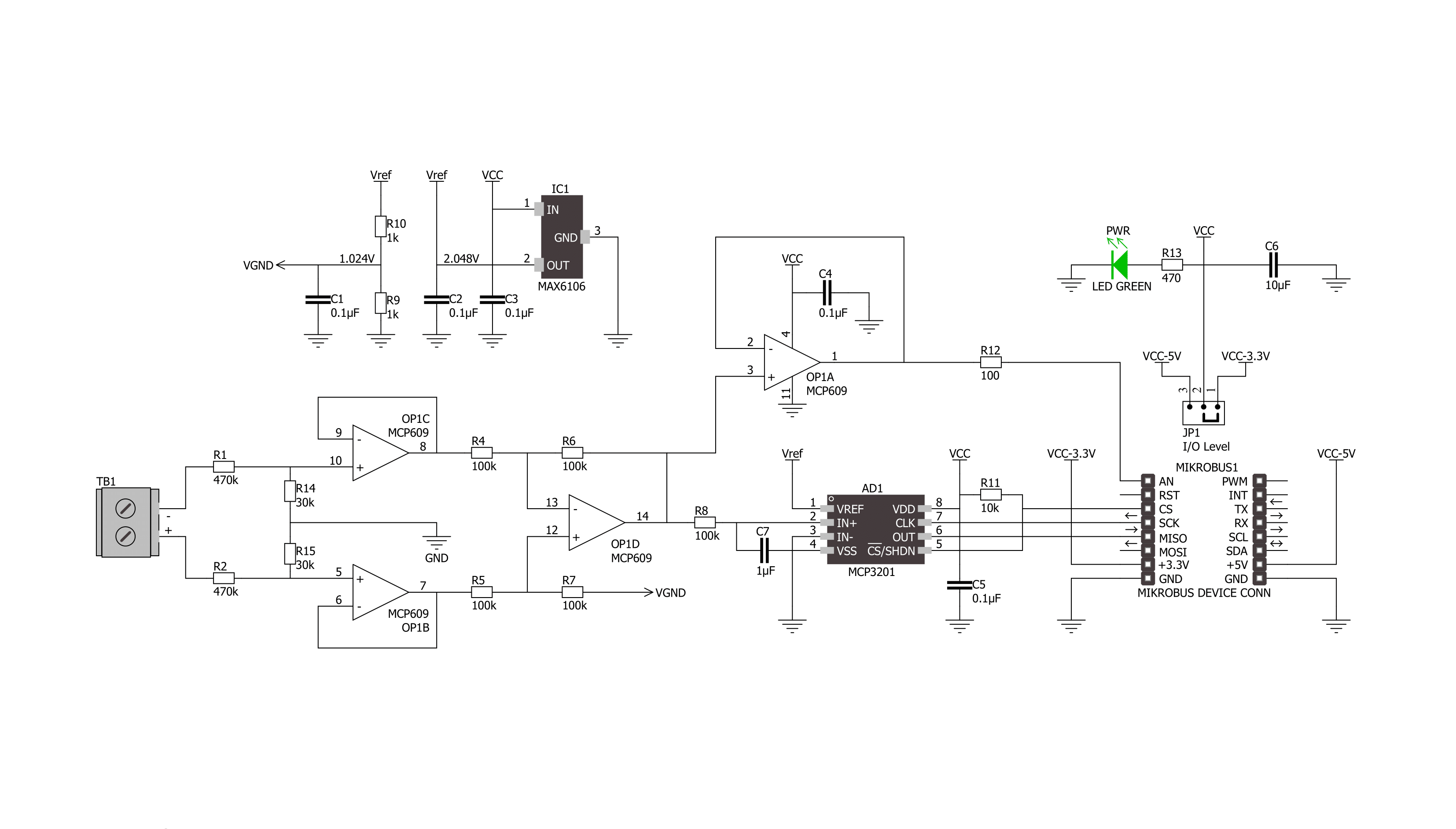
Voltage Click is based on the MCP609, a micropower CMOS operational amplifier from Microchip. It is a unity-gain stable, low offset voltage OpAmp that includes rail-to-rail output, swing capability, and low input bias current. On Voltage Click, the MCP609 is set as a differential amplifier with a buffer output. The current that comes through screw terminals flows through a row of four resistors. The last two resistors generate a voltage proportional to the input charge. From there, it is sent to the differential amplifier that further intensifies the difference between the two inputs (+/-). The resulting charge on MCP609 is exactly 33 times lower than the
actual measured voltage. This Click board™ features the MCP3201, a 12-bit AD converter with the SPI serial interface from Microchip. The MCP3201 provides a single pseudo-differential input, features on-chip sample and hold, a maximum sampling rate of up to 100ksps, and more. As reference voltage, the MCP3201 gets 2.048V from the MAX6106, a low-cost, micropower, low-dropout, high-output-current voltage reference from Analog Devices. The Voltmeter Click uses the 3-Wire SPI serial interface of the MCP3201 to communicate with the host MCU, supporting high clock frequency and SPI 0.0 and SPI 1.1 modes. The voltage amplified through the
MCP609 can be directly monitored through the AN pin of the mikroBUS™ socket, which is useful if the host MCU has a higher ADC resolution. The firmware on the host MCU should be set to multiply the ADC value to get the actual voltage from the SPI interface. This Click board™ can operate with either 3.3V or 5V logic voltage levels selected via the PWR SEL jumper. This way, both 3.3V and 5V capable MCUs can use the communication lines properly. Also, this Click board™ comes equipped with a library containing easy-to-use functions and an example code that can be used as a reference for further development.


Features overview
Development board
Fusion for TIVA v8 is a development board specially designed for the needs of rapid development of embedded applications. It supports a wide range of microcontrollers, such as different 32-bit ARM® Cortex®-M based MCUs from Texas Instruments, regardless of their number of pins, and a broad set of unique functions, such as the first-ever embedded debugger/programmer over a WiFi network. The development board is well organized and designed so that the end-user has all the necessary elements, such as switches, buttons, indicators, connectors, and others, in one place. Thanks to innovative manufacturing technology, Fusion for TIVA v8 provides a fluid and immersive working experience, allowing access
anywhere and under any circumstances at any time. Each part of the Fusion for TIVA v8 development board contains the components necessary for the most efficient operation of the same board. An advanced integrated CODEGRIP programmer/debugger module offers many valuable programming/debugging options, including support for JTAG, SWD, and SWO Trace (Single Wire Output)), and seamless integration with the Mikroe software environment. Besides, it also includes a clean and regulated power supply module for the development board. It can use a wide range of external power sources, including a battery, an external 12V power supply, and a power source via the USB Type-C (USB-C) connector.
Communication options such as USB-UART, USB HOST/DEVICE, CAN (on the MCU card, if supported), and Ethernet is also included. In addition, it also has the well-established mikroBUS™ standard, a standardized socket for the MCU card (SiBRAIN standard), and two display options for the TFT board line of products and character-based LCD. Fusion for TIVA v8 is an integral part of the Mikroe ecosystem for rapid development. Natively supported by Mikroe software tools, it covers many aspects of prototyping and development thanks to a considerable number of different Click boards™ (over a thousand boards), the number of which is growing every day.

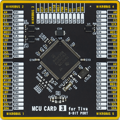
Microcontroller Overview
MCU Card / MCU
Type
8th Generation
Architecture
ARM Cortex-M4
MCU Memory (KB)
512
Silicon Vendor
Texas Instruments
Pin count
128
RAM (Bytes)
262144
Used MCU Pins
mikroBUS™ mapper
Take a closer look
Click board™ Schematic
Step by step
Project assembly

Start by selecting your development board and Click board™. Begin with the Fusion for Tiva v8 as your development board.


Track your results in real time
Application Output
1. Application Output - In Debug mode, the 'Application Output' window enables real-time data monitoring, offering direct insight into execution results. Ensure proper data display by configuring the environment correctly using the provided tutorial.

2. UART Terminal - Use the UART Terminal to monitor data transmission via a USB to UART converter, allowing direct communication between the Click board™ and your development system. Configure the baud rate and other serial settings according to your project's requirements to ensure proper functionality. For step-by-step setup instructions, refer to the provided tutorial.

3. Plot Output - The Plot feature offers a powerful way to visualize real-time sensor data, enabling trend analysis, debugging, and comparison of multiple data points. To set it up correctly, follow the provided tutorial, which includes a step-by-step example of using the Plot feature to display Click board™ readings. To use the Plot feature in your code, use the function: plot(*insert_graph_name*, variable_name);. This is a general format, and it is up to the user to replace 'insert_graph_name' with the actual graph name and 'variable_name' with the parameter to be displayed.

Software Support
Library Description
This library contains API for Voltmeter Click driver.
Key functions:
voltmeter_read_raw_data- This function reads raw ADC valuevoltmeter_calculate_voltage- This function converts the raw ADC value to proportional voltage level.
Open Source
Code example
The complete application code and a ready-to-use project are available through the NECTO Studio Package Manager for direct installation in the NECTO Studio. The application code can also be found on the MIKROE GitHub account.
/*!
 * \file
 * \brief Voltmeter Click example
 *
 * # Description
 * This application reads the voltage measurement and displays the results on the USB UART.
 *
 * The demo application is composed of two sections :
 *
 * ## Application Init
 * Initialization the driver and logger.
 *
 * ## Application Task
 * Reads the raw ADC measurement once per second and converts it to the proportional voltage level.
 * All data are being displayed on the USB UART where you can track their changes.
 *
 * \author MikroE Team
 *
 */
// ------------------------------------------------------------------- INCLUDES

#include "board.h"
#include "log.h"
#include "voltmeter.h"

// ------------------------------------------------------------------ VARIABLES

static voltmeter_t voltmeter;
static log_t logger;

void application_init ( void )
{
    log_cfg_t log_cfg;
    voltmeter_cfg_t cfg;

    /**
     * Logger initialization.
     * Default baud rate: 115200
     * Default log level: LOG_LEVEL_DEBUG
     * @note If USB_UART_RX and USB_UART_TX
     * are defined as HAL_PIN_NC, you will
     * need to define them manually for log to work.
     * See @b LOG_MAP_USB_UART macro definition for detailed explanation.
     */
    LOG_MAP_USB_UART( log_cfg );
    log_init( &logger, &log_cfg );
    log_info( &logger, " Application Init " );

    //  Click initialization.
    voltmeter_cfg_setup( &cfg );
    VOLTMETER_MAP_MIKROBUS( cfg, MIKROBUS_1 );
    voltmeter_init( &voltmeter, &cfg );
    Delay_ms ( 100 );

    log_info( &logger, " Application Task " );
}

void application_task ( void )
{
    int16_t adc_value = 0;
    float voltage = 0;

    adc_value = voltmeter_read_raw_data( &voltmeter );
    log_printf( &logger, " ADC Value: %d\r\n", adc_value );

    voltage = voltmeter_calculate_voltage( &voltmeter, adc_value, VOLTMETER_GND_ISO );
    log_printf( &logger, " Voltage  : %.3f V\r\n", voltage );
    log_printf( &logger, "------------------------\r\n");
    Delay_ms ( 1000 );
}

int main ( void )
{
    /* Do not remove this line or clock might not be set correctly. */
    #ifdef PREINIT_SUPPORTED
    preinit();
    #endif

    application_init( );

    for ( ; ; )
    {
        application_task( );
    }

    return 0;
}


// ------------------------------------------------------------------------ END


