Optimize efficiency through digital VCP monitoring based on the INA260 and STM32F031K6
Your digital guide to current and power excellence!

Published Oct 01, 2024
Click board™
VCP Monitor Click
Dev. board
Nucleo 32 with STM32F031K6 MCU
Compiler
NECTO Studio
MCU
STM32F031K6
From real-time diagnostics to performance optimization, the possibilities are endless
A
A
Hardware Overview
How does it work?
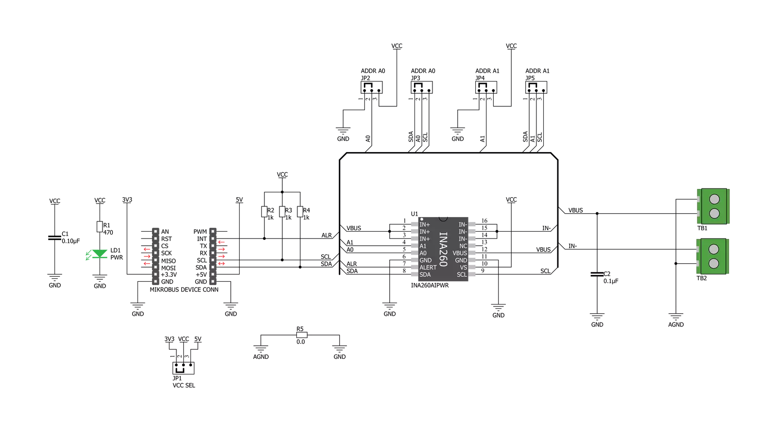
VCP Monitor Click is based on the INA260, a power monitor solution from Texas Instruments, which includes precision measurement of current, voltage, and power with low drift. The current-sensing resistor is designed as a 4-wire connected resistor that enables accurate measurements through a force-sense connection. The INA260 is internally calibrated to ensure the current-sensing resistor and amplifier are precisely matched. The INA260 device performs two measurements on the power supply bus. The current measurement on the LOAD connector is internally calculated by measuring the voltage developed across a known internal shunt resistor. The feature is a physical shunt resistance that can withstand current levels higher than the continuous handling limit of 15A without sustaining damage to the current-sensing resistor or the current-sensing amplifier if the excursions are brief. The voltage measurement on
the SUPPLY connector is calculated by measuring the voltage from the external VBUS pin to the ground. The voltage monitored ranges from 0V to 36V. The INA260 device performs two measurements on the power supply bus. The current measurement on the LOAD connector is internally calculated by measuring the voltage developed across a known internal shunt resistor, and the voltage measurement on the SUPPLY connector is calculated by measuring the voltage from the external VBUS pin to the ground. The VCP Monitor click is compatible with the I2C communication protocol. The INA260 has two slave address selection pins, A0 and A1. For I2C slave address selection, the VCP Monitor click has two cross-shape jumpers, first for set pin A0 and second for set A1 pin. One cross-shape jumper has four positions for the select address pins, which can be selected with an SMD 0 ohm resistor; the
address pin can be connected to GND, VS, SCL, or SDA pins. The VCP Monitor Clicks with the two separate jumpers on the Click board™ user can set the desired address. The INA260AIPWR provides the opportunity of the 16 possible different I2C addresses. The INA260AIPWR is supported with an ALERT pin connected to the INT pin on mikroBUS™ to interrupt the ongoing MCU routine in case of the alert condition. INT pin can be programmed to respond to a user-defined event or a conversion-ready notification. This Click board™ can operate with either 3.3V or 5V logic voltage levels selected via the VCC SEL jumper. This way, both 3.3V and 5V capable MCUs can use the communication lines properly. Also, this Click board™ comes equipped with a library containing easy-to-use functions and an example code that can be used, as a reference, for further development.


Features overview
Development board
Nucleo 32 with STM32F031K6 MCU board provides an affordable and flexible platform for experimenting with STM32 microcontrollers in 32-pin packages. Featuring Arduino™ Nano connectivity, it allows easy expansion with specialized shields, while being mbed-enabled for seamless integration with online resources. The
board includes an on-board ST-LINK/V2-1 debugger/programmer, supporting USB reenumeration with three interfaces: Virtual Com port, mass storage, and debug port. It offers a flexible power supply through either USB VBUS or an external source. Additionally, it includes three LEDs (LD1 for USB communication, LD2 for power,
and LD3 as a user LED) and a reset push button. The STM32 Nucleo-32 board is supported by various Integrated Development Environments (IDEs) such as IAR™, Keil®, and GCC-based IDEs like AC6 SW4STM32, making it a versatile tool for developers.

Microcontroller Overview
MCU Card / MCU

Architecture
ARM Cortex-M0
MCU Memory (KB)
32
Silicon Vendor
STMicroelectronics
Pin count
32
RAM (Bytes)
4096
You complete me!
Accessories
Click Shield for Nucleo-32 is the perfect way to expand your development board's functionalities with STM32 Nucleo-32 pinout. The Click Shield for Nucleo-32 provides two mikroBUS™ sockets to add any functionality from our ever-growing range of Click boards™. We are fully stocked with everything, from sensors and WiFi transceivers to motor control and audio amplifiers. The Click Shield for Nucleo-32 is compatible with the STM32 Nucleo-32 board, providing an affordable and flexible way for users to try out new ideas and quickly create prototypes with any STM32 microcontrollers, choosing from the various combinations of performance, power consumption, and features. The STM32 Nucleo-32 boards do not require any separate probe as they integrate the ST-LINK/V2-1 debugger/programmer and come with the STM32 comprehensive software HAL library and various packaged software examples. This development platform provides users with an effortless and common way to combine the STM32 Nucleo-32 footprint compatible board with their favorite Click boards™ in their upcoming projects.

Used MCU Pins
mikroBUS™ mapper
Take a closer look
Click board™ Schematic
Step by step
Project assembly

Start by selecting your development board and Click board™. Begin with the Nucleo 32 with STM32F031K6 MCU as your development board.


Software Support
Library Description
This library contains API for VCP Monitor Click driver.
Key functions:
vcpmonitor_get_current- This function reads current data in mAvcpmonitor_get_power- This function reads power data in mWvcpmonitor_get_voltage- This function reads voltage data in mV.
Open Source
Code example
The complete application code and a ready-to-use project are available through the NECTO Studio Package Manager for direct installation in the NECTO Studio. The application code can also be found on the MIKROE GitHub account.
/*!
 * \file
 * \brief VCPmonitor Click example
 *
 * # Description
 * The VCP Monitor Click is add-on board power monitor system. This Click board is
 * based on precision digital current and power monitor with low-drift, integrated
 * precision shunt resistor.
 *
 * The demo application is composed of two sections :
 *
 * ## Application Init
 * Initiaizes the driver, and checks the communication by reading the device and manufacture IDs.
 * After that, performs the device default configuration.
 *
 * ## Application Task
 * Displays the voltage, current, and power measured by the sensor on the USB UART every 2 seconds.
 *
 * \author MikroE Team
 *
 */
// ------------------------------------------------------------------- INCLUDES

#include "board.h"
#include "log.h"
#include "vcpmonitor.h"

// ------------------------------------------------------------------ VARIABLES

static vcpmonitor_t vcpmonitor;
static log_t logger;
static uint16_t manufacture_id;
static uint16_t did_id;

// ------------------------------------------------------ APPLICATION FUNCTIONS

void application_init ( void )
{
    log_cfg_t log_cfg;
    vcpmonitor_cfg_t cfg;

    /**
     * Logger initialization.
     * Default baud rate: 115200
     * Default log level: LOG_LEVEL_DEBUG
     * @note If USB_UART_RX and USB_UART_TX
     * are defined as HAL_PIN_NC, you will
     * need to define them manually for log to work.
     * See @b LOG_MAP_USB_UART macro definition for detailed explanation.
     */
    LOG_MAP_USB_UART( log_cfg );
    log_init( &logger, &log_cfg );
    log_info( &logger, "---- Application Init ----" );

    vcpmonitor_cfg_setup( &cfg );
    VCPMONITOR_MAP_MIKROBUS( cfg, MIKROBUS_1 );
    vcpmonitor_init( &vcpmonitor, &cfg );

    if ( VCPMONITOR_OK == vcpmonitor_get_id_value( &vcpmonitor, &manufacture_id, &did_id ) )
    {
        log_printf( &logger, ">> Manufacture ID: 0x%.4X\r\n", manufacture_id );
        log_printf( &logger, ">> Device ID: 0x%.4X\r\n", did_id );
    }
    else
    {
        log_error( &logger, " WRONG ID READ! " );
        log_printf( &logger, "Please restart your system.\r\n" );
        for ( ; ; );
    }

    vcpmonitor_default_cfg(&vcpmonitor );
    Delay_ms ( 500 );
}

void application_task ( void )
{
    float current_data;
    float voltage_data;
    float power_data;

    current_data = vcpmonitor_get_current( &vcpmonitor );
    log_printf( &logger, ">> Current : %.2f mA\r\n", current_data );

    voltage_data = vcpmonitor_get_voltage( &vcpmonitor );
    log_printf( &logger, ">> Voltage : %.2f mV\r\n", voltage_data );

    power_data = vcpmonitor_get_power( &vcpmonitor );
    log_printf( &logger, ">> Power : %.2f mW\r\n", power_data );

    log_printf( &logger, "-------------------------------\r\n" );
    Delay_ms ( 1000 );
    Delay_ms ( 1000 );
}

int main ( void )
{
    /* Do not remove this line or clock might not be set correctly. */
    #ifdef PREINIT_SUPPORTED
    preinit();
    #endif

    application_init( );

    for ( ; ; )
    {
        application_task( );
    }

    return 0;
}


// ------------------------------------------------------------------------ END
Additional Support
Resources
Category:Measurements


