Provide clear visual feedback and signal knob's position with EC12D1564402 and PIC32MZ2048EFM100
Symphony of motion and light
Published Jul 22, 2025
Click board™
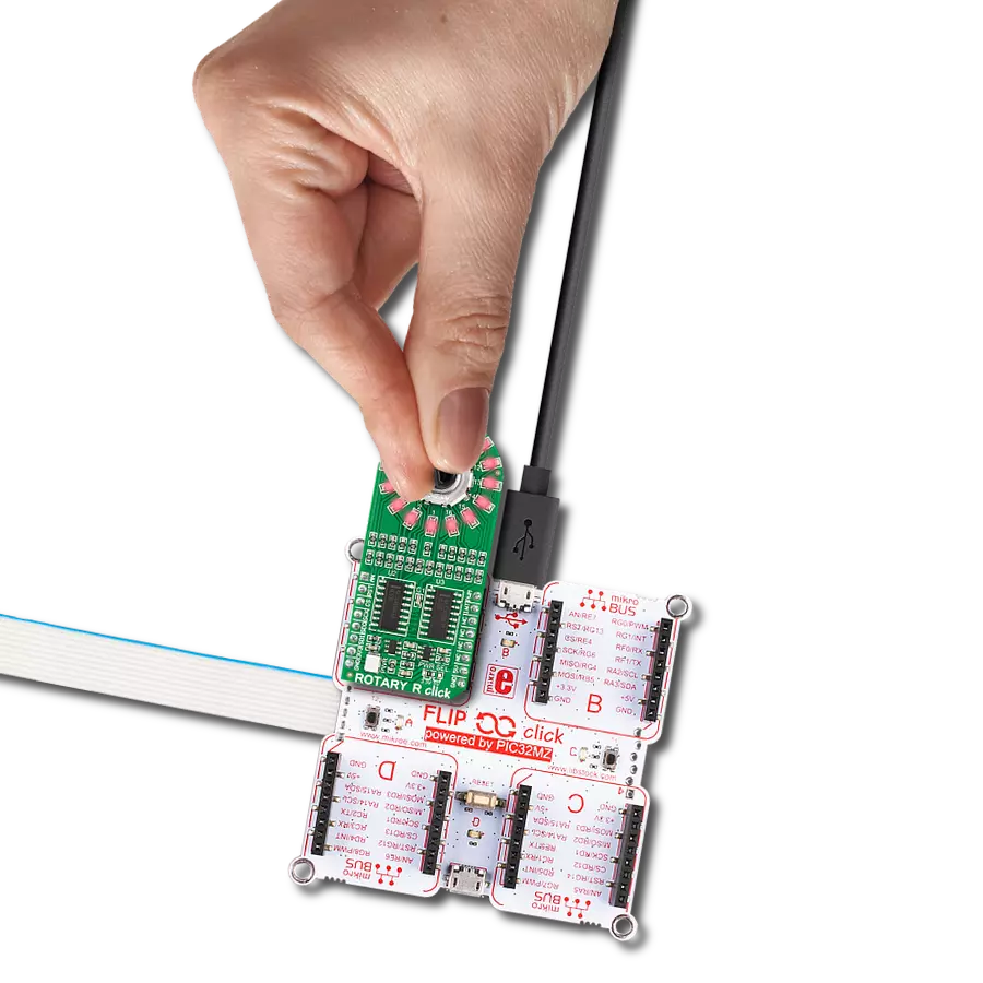
ROTARY B Click
Dev. board
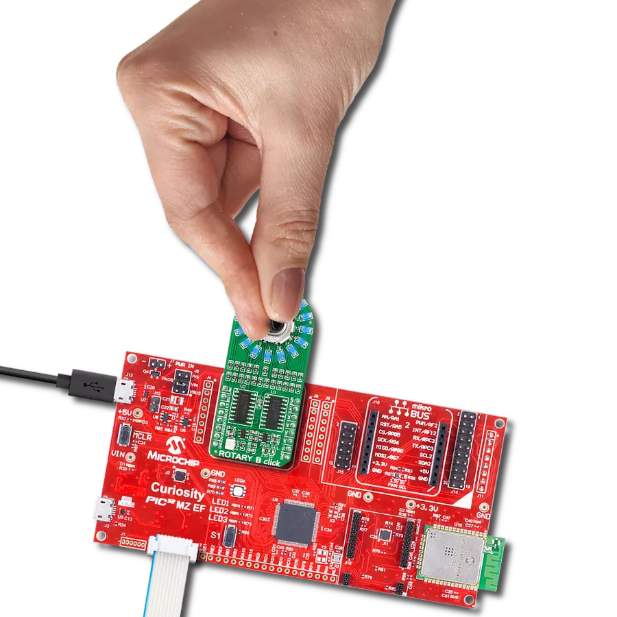
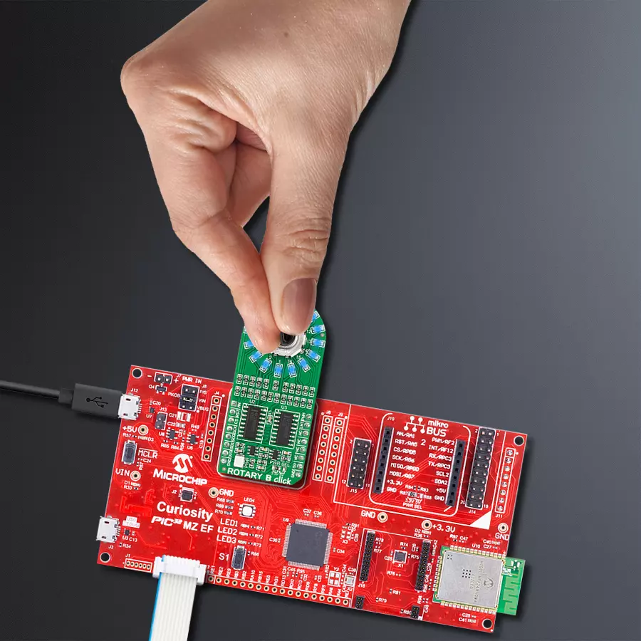
Curiosity PIC32 MZ EF
Compiler
NECTO Studio
MCU
PIC32MZ2048EFM100
Our cutting-edge rotary solution embraces a striking blue LED ring, defining your every move
A
A
Hardware Overview
How does it work?
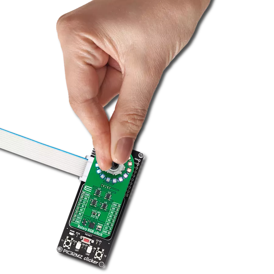
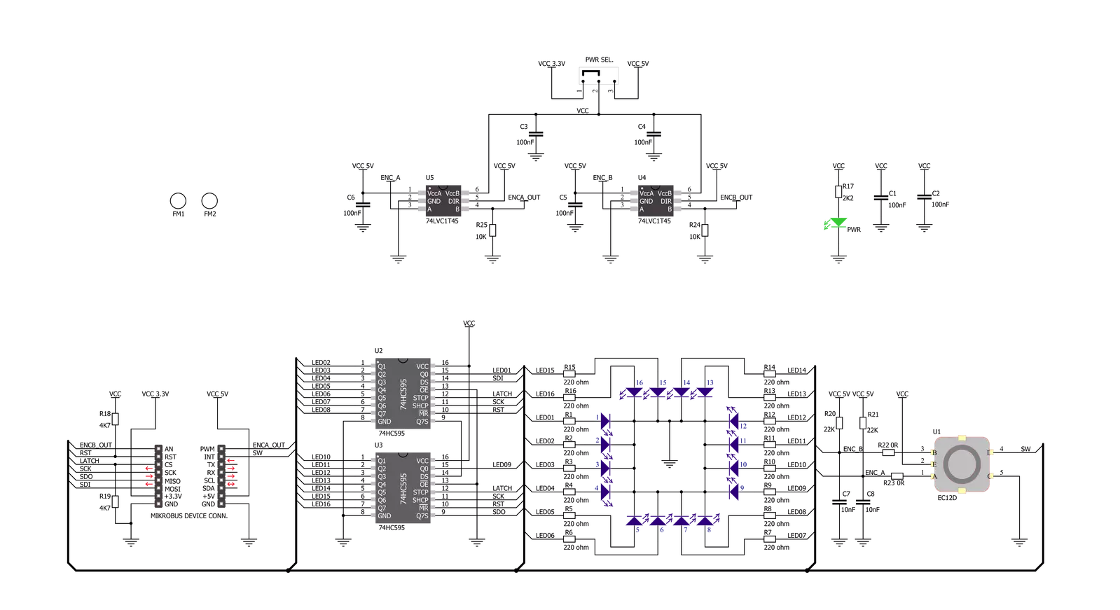
ROTARY B Click is based on two SN74HC595 SPI-configurable 8-bit shift registers from Texas Instruments that, combined with a high-quality rotary encoder, the EC12D1564402, allows you to add a precision input knob to your design. The EC12D1564402 incremental rotary encoder is surrounded by a ring of 16 blue LEDs where a single rotation is divided into 15 discrete steps (in contrast to a potentiometer, a rotary encoder can be spun around continuously). This Click board™ is an ideal solution for building various HMI applications where precise input is required, but also for some interesting visual effects to any application. As mentioned, this Click board™ uses
the EC12D1564402, a 15-pulse incremental rotary encoder with a push-button, from ALPS. This encoder has unique mechanical specifications (debouncing time for its internal switches goes down to 2ms) and can withstand many switching cycles, up to 30.000. The supporting debouncing circuitry allows contacts to settle before the output is triggered fully. The SN74HC595 controls each LED individually positioned in a ring around the encoder through a standard SPI interface with a maximum frequency of 5MHz. Rotating the encoder, it outputs A and B signals (out of phase to each other) on the two mikroBUS™ lines, AN and PWM pins of the mikroBUS™ socket,
alongside the push-button contact, which outputs through the interrupt line of the mikroBUS™ socket. The SN74HC595 also has a Reset feature used across the RST mikroBUS™ line. This Click board™ can operate with both 3.3V and 5V logic voltage levels selected via the PWR SEL jumper. This way, it is allowed for both 3.3V and 5V capable MCUs to use the communication lines properly. However, the Click board™ comes equipped with a library containing easy-to-use functions and an example code that can be used, as a reference, for further development.

Features overview
Development board
Curiosity PIC32 MZ EF development board is a fully integrated 32-bit development platform featuring the high-performance PIC32MZ EF Series (PIC32MZ2048EFM) that has a 2MB Flash, 512KB RAM, integrated FPU, Crypto accelerator, and excellent connectivity options. It includes an integrated programmer and debugger, requiring no additional hardware. Users can expand
functionality through MIKROE mikroBUS™ Click™ adapter boards, add Ethernet connectivity with the Microchip PHY daughter board, add WiFi connectivity capability using the Microchip expansions boards, and add audio input and output capability with Microchip audio daughter boards. These boards are fully integrated into PIC32’s powerful software framework, MPLAB Harmony,
which provides a flexible and modular interface to application development a rich set of inter-operable software stacks (TCP-IP, USB), and easy-to-use features. The Curiosity PIC32 MZ EF development board offers expansion capabilities making it an excellent choice for a rapid prototyping board in Connectivity, IOT, and general-purpose applications.

Microcontroller Overview
MCU Card / MCU

Architecture
PIC32
MCU Memory (KB)
2048
Silicon Vendor
Microchip
Pin count
100
RAM (Bytes)
524288
Used MCU Pins
mikroBUS™ mapper
Take a closer look
Click board™ Schematic
Step by step
Project assembly

Start by selecting your development board and Click board™. Begin with the Curiosity PIC32 MZ EF as your development board.


Software Support
Library Description
This library contains API for ROTARY B Click driver.
Key functions:
rotaryb_generic_transfer- ROTARY B data transfer function.rotaryb_turn_on_led_by_position- Function turn on led by positionrotaryb_button_push- Function return 1 if button is pushed and return 0 if not
Open Source
Code example
The complete application code and a ready-to-use project are available through the NECTO Studio Package Manager for direct installation in the NECTO Studio. The application code can also be found on the MIKROE GitHub account.
/*!
 * @file main.c
 * @brief Rotary B Click example
 *
 * # Description
 * The demo application controls led on Click with rotary on board.
 *
 * The demo application is composed of two sections :
 *
 * ## Application Init
 * Initializes SPI driver, set initial states,
 * set RST logic high and performs device configuration.
 *
 * ## Application Task
 * Show functionality of Rotary B Click, rotating and turn on/off led's,
 * using the SPI interface.
 *
 * @note
 * In orther to use all of the Clicks functionality, pull down INT pin.
 *
 * @author Stefan Ilic
 *
 */

#include "board.h"
#include "log.h"
#include "rotaryb.h"

static rotaryb_t rotaryb;
static log_t logger;

static uint8_t start_status;
static uint8_t old_state;
static uint8_t new_state;
static uint8_t old__rot_state;
static uint8_t new_rotate_state;
static uint8_t led_state;
static uint16_t led_data;

void application_init ( void ) {
    log_cfg_t log_cfg;  /**< Logger config object. */
    rotaryb_cfg_t rotaryb_cfg;  /**< Click config object. */

    /**
     * Logger initialization.
     * Default baud rate: 115200
     * Default log level: LOG_LEVEL_DEBUG
     * @note If USB_UART_RX and USB_UART_TX
     * are defined as HAL_PIN_NC, you will
     * need to define them manually for log to work.
     * See @b LOG_MAP_USB_UART macro definition for detailed explanation.
     */
    LOG_MAP_USB_UART( log_cfg );
    log_init( &logger, &log_cfg );
    log_info( &logger, " Application Init " );

    // Click initialization.

    rotaryb_cfg_setup( &rotaryb_cfg );
    ROTARYB_MAP_MIKROBUS( rotaryb_cfg, MIKROBUS_1 );
    err_t init_flag  = rotaryb_init( &rotaryb, &rotaryb_cfg );
    if ( init_flag == SPI_MASTER_ERROR ) {
        log_error( &logger, " Application Init Error. " );
        log_info( &logger, " Please, run program again... " );

        for ( ; ; );
    }

    log_info( &logger, " Application Task " );

    led_data = 0x0001;
    old_state = 0;
    new_state = 1;
    old__rot_state = 0;
    new_rotate_state = 1;
}

void application_task ( void ) {
    rotaryb_turn_on_led_by_data( &rotaryb, led_data );

//     Push button
    if ( rotaryb_button_push( &rotaryb ) ) {
        new_state = 1;
        if ( new_state == 1 && old_state == 0 ) {
            old_state = 1;
            led_state = ( led_state + 1 ) % 5;
            if ( led_state == 4 ) {
                for ( old_state = 0; old_state < 17; old_state++ ) {
                    rotaryb_turn_on_led_by_data( &rotaryb, 0xAAAA );
                    Delay_ms ( 100 );
                    rotaryb_turn_on_led_by_data( &rotaryb, 0x5555 );
                    Delay_ms ( 100 );
                }

                for ( old_state = 0; old_state < 17; old_state++ ) {
                    rotaryb_turn_on_led_by_position( &rotaryb, old_state );
                    Delay_ms ( 100 );
                }

                led_state = 0;
                led_data = rotaryb_get_led_data( led_state );
            }
            else {
                led_data = rotaryb_get_led_data( led_state );
            }
        }
    }
    else {
        old_state = 0;
    }

//     Rotate Clockwise and CounterClockwise
    if ( rotaryb_get_eca_state( &rotaryb ) == rotaryb_get_ecb_state( &rotaryb ) ) {
        old__rot_state = 0;
        start_status = rotaryb_get_eca_state( &rotaryb ) && rotaryb_get_ecb_state( &rotaryb );
    }
    else {
        new_rotate_state = 1;
        if ( new_rotate_state != old__rot_state ) {
            old__rot_state = 1;
            if ( start_status != rotaryb_get_eca_state( &rotaryb ) ) {
                led_data = ( led_data << 1 ) | ( led_data >> 15 );
            }
            else {
                led_data = ( led_data >> 1 ) | ( led_data << 15 );
            }
        }
    }
}

int main ( void )
{
    /* Do not remove this line or clock might not be set correctly. */
    #ifdef PREINIT_SUPPORTED
    preinit();
    #endif

    application_init( );

    for ( ; ; )
    {
        application_task( );
    }

    return 0;
}

// ------------------------------------------------------------------------ END
Additional Support
Resources
Category:Rotary encoder