Create visually appealing and interactive lighting displays with 1312121320437 and STM32L442KC
2x4 RGB LED matrix for dynamic and colorful lighting effects

Published Oct 08, 2024
Click board™
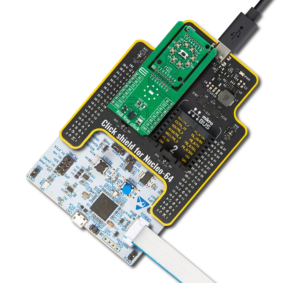
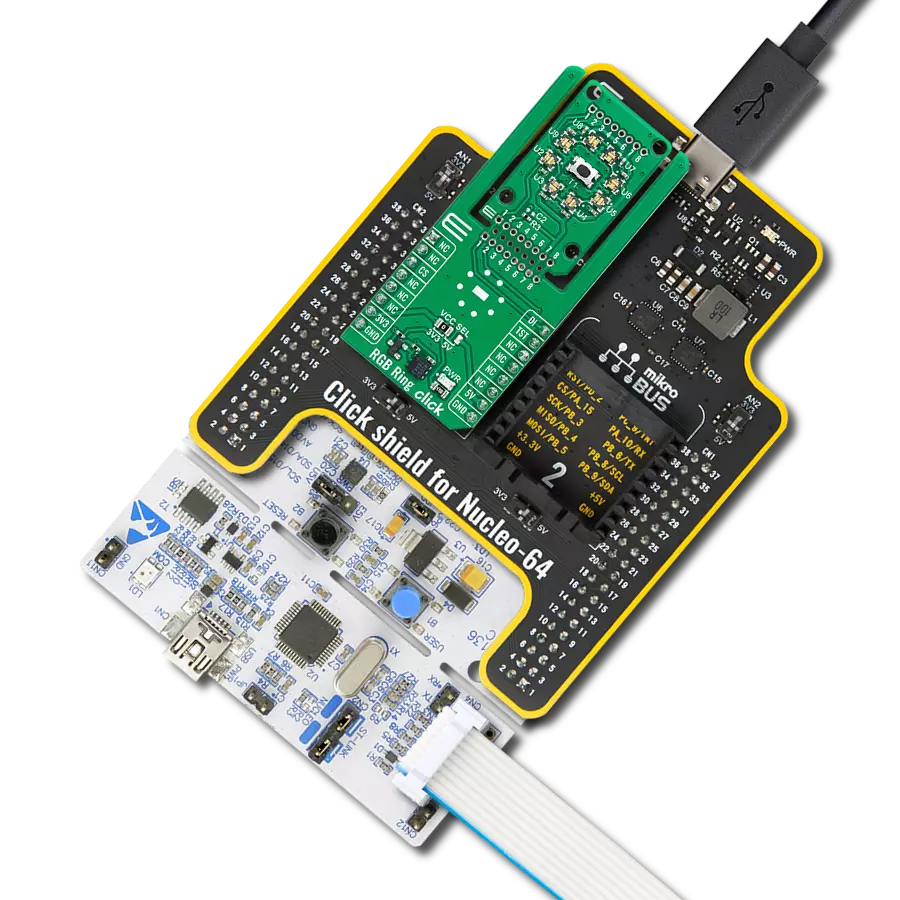
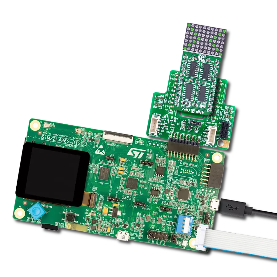
2x4 RGB Click
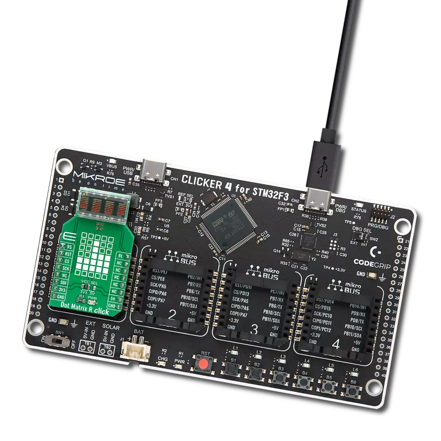
Dev. board
Fusion for ARM v8
Compiler
NECTO Studio
MCU
STM32L442KC
Provide dynamic and eye-catching visual displays for information or advertising
A
A
Hardware Overview
How does it work?
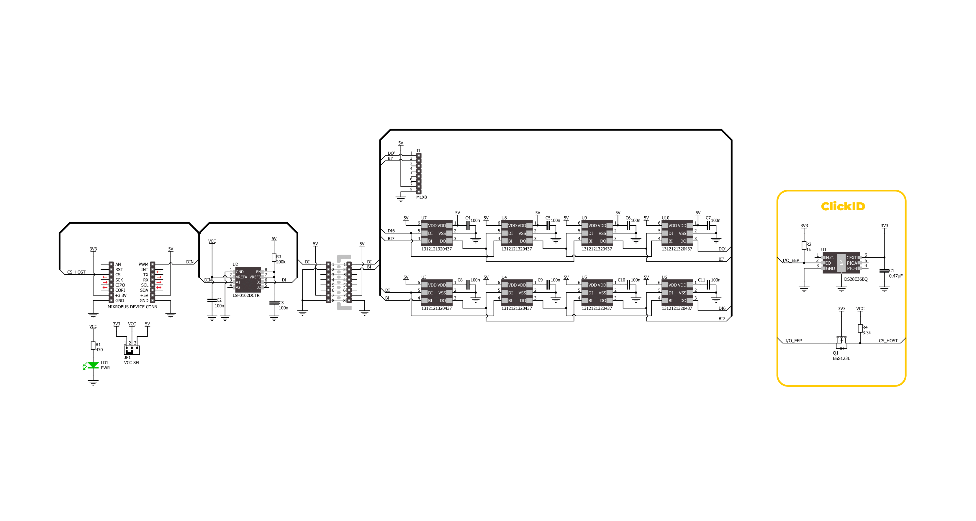
2x4 RGB Click is based on an array of 2x4 RGB LEDs (WL-ICLED 1312121320437) from Würth Elektronik, specially designed for dynamic and colorful lighting applications. These LEDs incorporate an integrated circuit (IC), often called addressable or smart LEDs, allowing for individual control of each diode's red, green, and blue components through pulse width modulation (PWM). This enables precise control over color mixing, creating a broad spectrum of color outputs. To ensure compatibility with both 3.3V and 5V logic systems, the Click board™ features the LSF0102 voltage translator, which provides seamless control
of the LEDs regardless of the MCU's logic level, ensuring reliable performance in various system configurations. 2x4 RGB Click is designed in a unique format supporting the newly introduced MIKROE feature called "Click Snap." Unlike the standardized version of Click boards, this feature allows the main IC area to become movable by breaking the PCB, opening up many new possibilities for implementation. Thanks to the Snap feature, the 1312121320437s can operate autonomously by accessing its signals directly on the pins marked 1-8. Additionally, the Snap part includes a specified and fixed screw hole position,
enabling users to secure the Snap board in their desired location, and an unpopulated header labeled J1 at the top, allowing for daisy-chaining and control of multiple Snap units in a series. This Click board™ can operate with either 3.3V or 5V logic voltage levels selected via the VCC SEL jumper. This way, both 3.3V and 5V capable MCUs can use the communication lines properly. Also, this Click board™ comes equipped with a library containing easy-to-use functions and an example code that can be used as a reference for further development.

Features overview
Development board
Fusion for ARM v8 is a development board specially designed for the needs of rapid development of embedded applications. It supports a wide range of microcontrollers, such as different ARM® Cortex®-M based MCUs regardless of their number of pins, and a broad set of unique functions, such as the first-ever embedded debugger/programmer over WiFi. The development board is well organized and designed so that the end-user has all the necessary elements, such as switches, buttons, indicators, connectors, and others, in one place. Thanks to innovative manufacturing technology, Fusion for ARM v8 provides a fluid and immersive working experience, allowing access anywhere and under any
circumstances at any time. Each part of the Fusion for ARM v8 development board contains the components necessary for the most efficient operation of the same board. An advanced integrated CODEGRIP programmer/debugger module offers many valuable programming/debugging options, including support for JTAG, SWD, and SWO Trace (Single Wire Output)), and seamless integration with the Mikroe software environment. Besides, it also includes a clean and regulated power supply module for the development board. It can use a wide range of external power sources, including a battery, an external 12V power supply, and a power source via the USB Type-C (USB-C) connector.
Communication options such as USB-UART, USB HOST/DEVICE, CAN (on the MCU card, if supported), and Ethernet is also included. In addition, it also has the well-established mikroBUS™ standard, a standardized socket for the MCU card (SiBRAIN standard), and two display options for the TFT board line of products and character-based LCD. Fusion for ARM v8 is an integral part of the Mikroe ecosystem for rapid development. Natively supported by Mikroe software tools, it covers many aspects of prototyping and development thanks to a considerable number of different Click boards™ (over a thousand boards), the number of which is growing every day.

Microcontroller Overview
MCU Card / MCU
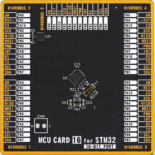
Type
8th Generation
Architecture
ARM Cortex-M4
MCU Memory (KB)
256
Silicon Vendor
STMicroelectronics
Pin count
32
RAM (Bytes)
65536
Used MCU Pins
mikroBUS™ mapper
Take a closer look
Click board™ Schematic
Step by step
Project assembly

Start by selecting your development board and Click board™. Begin with the Fusion for ARM v8 as your development board.


Track your results in real time
Application Output
1. Application Output - In Debug mode, the 'Application Output' window enables real-time data monitoring, offering direct insight into execution results. Ensure proper data display by configuring the environment correctly using the provided tutorial.

2. UART Terminal - Use the UART Terminal to monitor data transmission via a USB to UART converter, allowing direct communication between the Click board™ and your development system. Configure the baud rate and other serial settings according to your project's requirements to ensure proper functionality. For step-by-step setup instructions, refer to the provided tutorial.

3. Plot Output - The Plot feature offers a powerful way to visualize real-time sensor data, enabling trend analysis, debugging, and comparison of multiple data points. To set it up correctly, follow the provided tutorial, which includes a step-by-step example of using the Plot feature to display Click board™ readings. To use the Plot feature in your code, use the function: plot(*insert_graph_name*, variable_name);. This is a general format, and it is up to the user to replace 'insert_graph_name' with the actual graph name and 'variable_name' with the parameter to be displayed.

Software Support
Library Description
This library contains API for 2x4 RGB Click driver.
Key functions:
c2x4rgb_set_leds_intensity- This function sets the brightness and current gain level of all LEDs in the led matrix.c2x4rgb_set_led_color- This function sets the color of the selected LED in the LED matrix.c2x4rgb_write_led_matrix- This function writes the LED matrix data from the click context object.
Open Source
Code example
The complete application code and a ready-to-use project are available through the NECTO Studio Package Manager for direct installation in the NECTO Studio. The application code can also be found on the MIKROE GitHub account.
/*!
 * @file main.c
 * @brief 2x4 RGB Click Example.
 *
 * # Description
 * This example demonstrates the use of 2x4 RGB Click board by cycling through
 * a set of colors, gradually increasing the brightness of each LED in a sequence,
 * and then decreasing the brightness before moving on to the next color in the array.
 *
 * The demo application is composed of two sections :
 *
 * ## Application Init
 * Initializes the driver and performs the Click default configuration which sets
 * the LEDs brightness and current gain to a minimum and the color to black (all LEDs off).
 *
 * ## Application Task
 * Cycles through a set of colors, gradually increases the brightness of each LED
 * in a sequence, and then decreases the brightness before moving on to the next
 * color in the array. The current color's name and RGB value are logged to the USB UART.
 *
 * @author Stefan Filipovic
 *
 */

#include "board.h"
#include "log.h"
#include "c2x4rgb.h"
#include "c2x4rgb_delays.h"

static c2x4rgb_t c2x4rgb;   /**< 2x4 RGB Click driver object. */
static log_t logger;    /**< Logger object. */

static c2x4rgb_color_t color[ C2X4RGB_NUM_COLORS ] =
{
    { C2X4RGB_COLOR_BLACK, "BLACK" },
    { C2X4RGB_COLOR_WHITE, "WHITE" },
    { C2X4RGB_COLOR_RED, "RED" },
    { C2X4RGB_COLOR_LIME, "LIME" },
    { C2X4RGB_COLOR_BLUE, "BLUE" },
    { C2X4RGB_COLOR_YELLOW, "YELLOW" },
    { C2X4RGB_COLOR_CYAN, "CYAN" },
    { C2X4RGB_COLOR_MAGENTA, "MAGENTA" },
    { C2X4RGB_COLOR_SILVER, "SILVER" },
    { C2X4RGB_COLOR_GRAY, "GRAY" },
    { C2X4RGB_COLOR_MAROON, "MAROON" },
    { C2X4RGB_COLOR_OLIVE, "OLIVE" },
    { C2X4RGB_COLOR_GREEN, "GREEN" },
    { C2X4RGB_COLOR_PURPLE, "PURPLE" },
    { C2X4RGB_COLOR_TEAL, "TEAL" },
    { C2X4RGB_COLOR_NAVY, "NAVY" }
};

/**
 * @brief 2x4 RGB logic zero function.
 * @details This function toggles the data pin with exact high and low time pulse for logic zero.
 * @return None.
 * @note None.
 */
static void c2x4rgb_logic_zero ( void );

/**
 * @brief 2x4 RGB logic one function.
 * @details This function toggles the data pin with exact high and low time pulse for logic one.
 * @return None.
 * @note None.
 */
static void c2x4rgb_logic_one ( void );

void application_init ( void )
{
    log_cfg_t log_cfg;  /**< Logger config object. */
    c2x4rgb_cfg_t c2x4rgb_cfg;  /**< Click config object. */

    /**
     * Logger initialization.
     * Default baud rate: 115200
     * Default log level: LOG_LEVEL_DEBUG
     * @note If USB_UART_RX and USB_UART_TX
     * are defined as HAL_PIN_NC, you will
     * need to define them manually for log to work.
     * See @b LOG_MAP_USB_UART macro definition for detailed explanation.
     */
    LOG_MAP_USB_UART( log_cfg );
    log_init( &logger, &log_cfg );
    log_info( &logger, " Application Init " );

    // Click initialization.
    c2x4rgb_cfg_setup( &c2x4rgb_cfg );
    C2X4RGB_MAP_MIKROBUS( c2x4rgb_cfg, MIKROBUS_1 );
    if ( DIGITAL_OUT_UNSUPPORTED_PIN ==
         c2x4rgb_init( &c2x4rgb, &c2x4rgb_logic_zero, &c2x4rgb_logic_one, &c2x4rgb_cfg ) )
    {
        log_error( &logger, " Communication init." );
        for ( ; ; );
    }

    if ( C2X4RGB_ERROR == c2x4rgb_default_cfg ( &c2x4rgb ) )
    {
        log_error( &logger, " Default configuration." );
        for ( ; ; );
    }

    log_info( &logger, " Application Task " );
}

void application_task ( void )
{
    static uint32_t color_num = 0;
    static int8_t led_cnt = 0;
    static int8_t brightness = 0;
    log_printf( &logger, " Color: %s [%.6LX]\r\n\n", color[ color_num ].name, color[ color_num ].rgb );
    Delay_ms ( 100 );
    c2x4rgb_set_leds_intensity ( &c2x4rgb, C2X4RGB_LED_BRIGHTNESS_MIN, C2X4RGB_LED_CURRENT_GAIN_DEFAULT );
    for ( led_cnt = C2X4RGB_LED_7; led_cnt >= C2X4RGB_LED_0; led_cnt-- )
    {
        c2x4rgb_set_led_color ( &c2x4rgb, led_cnt, color[ color_num ].rgb );
        c2x4rgb_write_led_matrix ( &c2x4rgb );
        Delay_ms ( 100 );
    }
    for ( brightness = C2X4RGB_LED_BRIGHTNESS_MIN; brightness < C2X4RGB_LED_BRIGHTNESS_MAX; brightness++ )
    {
        c2x4rgb_set_leds_intensity ( &c2x4rgb, brightness, C2X4RGB_LED_CURRENT_GAIN_DEFAULT );
        c2x4rgb_write_led_matrix ( &c2x4rgb );
        Delay_ms ( 50 );
    }
    for ( brightness = C2X4RGB_LED_BRIGHTNESS_MAX; brightness >= C2X4RGB_LED_BRIGHTNESS_MIN; brightness-- )
    {
        c2x4rgb_set_leds_intensity ( &c2x4rgb, brightness, C2X4RGB_LED_CURRENT_GAIN_DEFAULT );
        c2x4rgb_write_led_matrix ( &c2x4rgb );
        Delay_ms ( 50 );
    }
    if ( ++color_num >= C2X4RGB_NUM_COLORS )
    {
        color_num = 0;
    }
}

int main ( void )
{
    /* Do not remove this line or clock might not be set correctly. */
    #ifdef PREINIT_SUPPORTED
    preinit();
    #endif

    application_init( );

    for ( ; ; )
    {
        application_task( );
    }

    return 0;
}

static void c2x4rgb_logic_zero ( void )
{
    hal_ll_gpio_set_pin_output( &c2x4rgb.din.pin );
    DELAY_TOH;
    hal_ll_gpio_clear_pin_output( &c2x4rgb.din.pin );
    DELAY_TOL;
}

static void c2x4rgb_logic_one ( void )
{
    hal_ll_gpio_set_pin_output( &c2x4rgb.din.pin );
    DELAY_T1H;
    hal_ll_gpio_clear_pin_output( &c2x4rgb.din.pin );
    DELAY_T1L;
}

// ------------------------------------------------------------------------ END
Additional Support
Resources
Category:LED Matrix