Enjoy in our power efficient, long range wireless communication solution based on 32001324 and TM4C129ENCPDT
Metering made easy: Your go-to solution
Published Nov 08, 2023
Click board™
M-BUS RF 4 Click
Dev. board
Fusion for Tiva v8
Compiler
NECTO Studio
MCU
TM4C129ENCPDT
Stay ahead in the world of metering solutions with the innovation and efficiency provided by our wireless M-Bus transceiver.
A
A
Hardware Overview
How does it work?
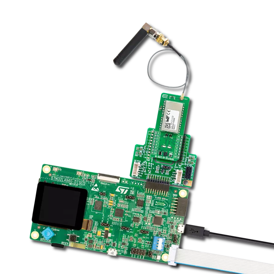
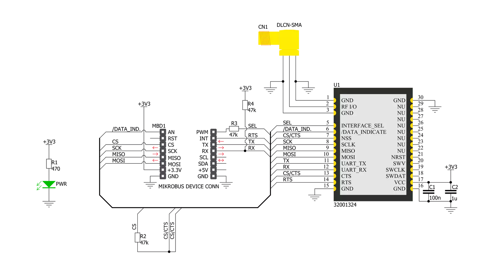
M-BUS RF 4 Click is based on the 32001324, an 868MHz band transceiver module from Mipot. The radio operates at the unlicensed 868 MHz SRD frequency band and has specified serial data rates of up to 115.2 Kbps. This M-BUS RF 4 click is ideal for developing various applications, mainly solutions for water or gas, as well as heat and electricity metering applications, and even on meter and concetrator devices. The module supports various operating modes (S, T, R, C) to meet the requirements of one-way and two-way data communication, in stationary and mobile systems. The embedded stack implemented according to EN13757-4 Standard provides the
physical access to the Wireless M-Bus communication. At startup time, the Module reads INTERFACE_SELECTION input pin state, which is routed to the PWM pin (marked SEL on Click board) of the mikroBUS™ socket. This pin should be left unconnected or set to high state to select the UART interface or set to low state to select the SPI interface for communicating with the main MCU. Widely used SPI and UART interfaces allow integration flexibility and easy development of customer products. The module meets all the requirements in the industrial temperature range -40/+85°C. Besides that, the module is also certified according to R&TTED 1999/05/EC
and is compliant with the ReACH And ROHS directives. The embedded stack implemented in the module according to EN13757-4 Standard provides the physical access to the Wireless M-Bus communication. M-BUS RF 4 click communicates with the target MCU through the mikroBUS™ UART or SPI interface, with additional functionality provided by IND, SEL, and RTS CS/CTS pins. This Click Board™ is designed to be operated only with 3.3V logic level. A proper logic voltage level conversion should be performed before the Click board™ is used with MCUs with logic levels of 5V.

Features overview
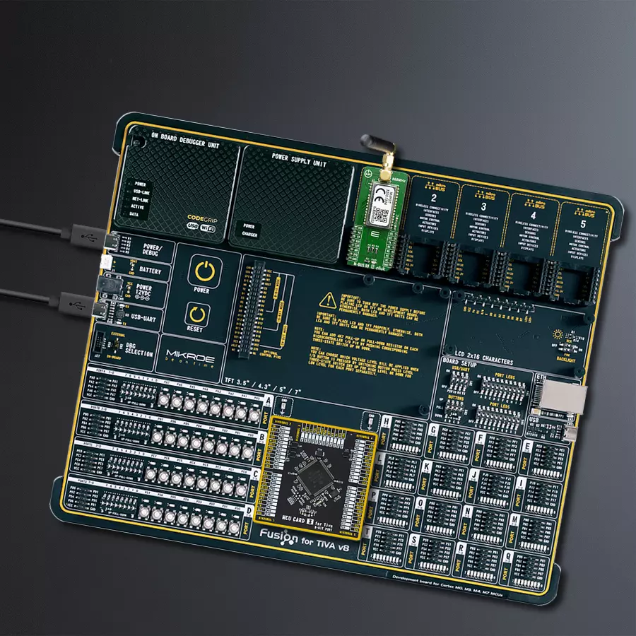
Development board
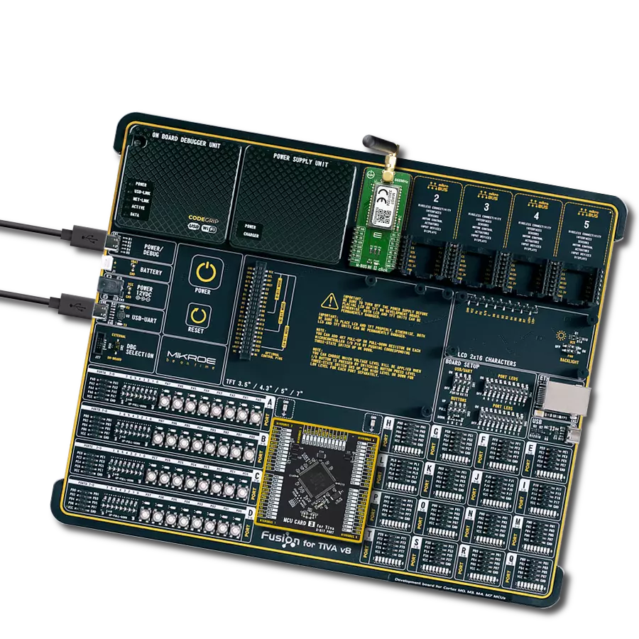
Fusion for TIVA v8 is a development board specially designed for the needs of rapid development of embedded applications. It supports a wide range of microcontrollers, such as different 32-bit ARM® Cortex®-M based MCUs from Texas Instruments, regardless of their number of pins, and a broad set of unique functions, such as the first-ever embedded debugger/programmer over a WiFi network. The development board is well organized and designed so that the end-user has all the necessary elements, such as switches, buttons, indicators, connectors, and others, in one place. Thanks to innovative manufacturing technology, Fusion for TIVA v8 provides a fluid and immersive working experience, allowing access
anywhere and under any circumstances at any time. Each part of the Fusion for TIVA v8 development board contains the components necessary for the most efficient operation of the same board. An advanced integrated CODEGRIP programmer/debugger module offers many valuable programming/debugging options, including support for JTAG, SWD, and SWO Trace (Single Wire Output)), and seamless integration with the Mikroe software environment. Besides, it also includes a clean and regulated power supply module for the development board. It can use a wide range of external power sources, including a battery, an external 12V power supply, and a power source via the USB Type-C (USB-C) connector.
Communication options such as USB-UART, USB HOST/DEVICE, CAN (on the MCU card, if supported), and Ethernet is also included. In addition, it also has the well-established mikroBUS™ standard, a standardized socket for the MCU card (SiBRAIN standard), and two display options for the TFT board line of products and character-based LCD. Fusion for TIVA v8 is an integral part of the Mikroe ecosystem for rapid development. Natively supported by Mikroe software tools, it covers many aspects of prototyping and development thanks to a considerable number of different Click boards™ (over a thousand boards), the number of which is growing every day.

Microcontroller Overview
MCU Card / MCU

Type
8th Generation
Architecture
ARM Cortex-M4
MCU Memory (KB)
1024
Silicon Vendor
Texas Instruments
Pin count
128
RAM (Bytes)
262144
You complete me!
Accessories
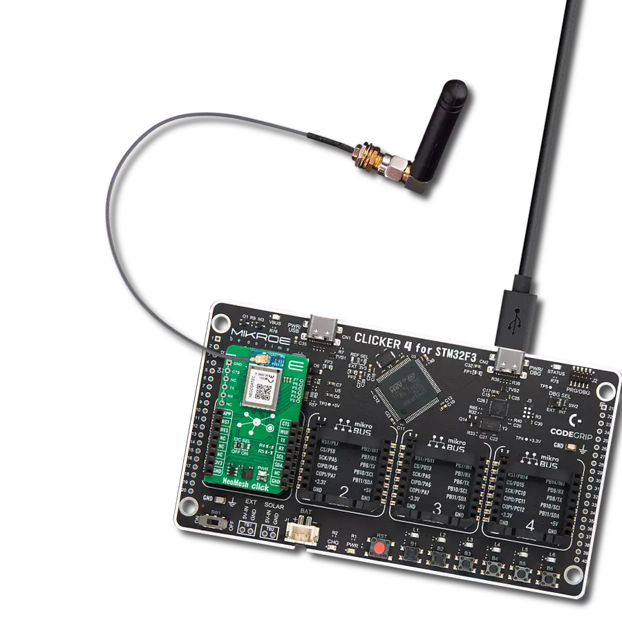
868MHz right-angle rubber antenna is a compact and versatile solution for wireless communication. Operating within the frequency range of 868-915MHz, it ensures optimal signal reception and transmission. With a 50-ohm impedance, it's compatible with various devices and systems. This antenna boasts a 2dB gain, enhancing signal strength and extending communication range. Its vertical polarization further contributes to signal clarity. Designed to handle up to 50W of input power, it's a robust choice for various applications. Measuring just 48mm in length, this antenna is both discreet and practical. Its SMA male connector ensures a secure and reliable connection to your equipment. Whether you're working with IoT devices, remote sensors, or other wireless technologies, the 868MHz right-angle antenna offers the performance and flexibility you need for seamless communication.

Used MCU Pins
mikroBUS™ mapper
Take a closer look
Click board™ Schematic
Step by step
Project assembly

Start by selecting your development board and Click board™. Begin with the Fusion for Tiva v8 as your development board.


Track your results in real time
Application Output
1. Application Output - In Debug mode, the 'Application Output' window enables real-time data monitoring, offering direct insight into execution results. Ensure proper data display by configuring the environment correctly using the provided tutorial.

2. UART Terminal - Use the UART Terminal to monitor data transmission via a USB to UART converter, allowing direct communication between the Click board™ and your development system. Configure the baud rate and other serial settings according to your project's requirements to ensure proper functionality. For step-by-step setup instructions, refer to the provided tutorial.

3. Plot Output - The Plot feature offers a powerful way to visualize real-time sensor data, enabling trend analysis, debugging, and comparison of multiple data points. To set it up correctly, follow the provided tutorial, which includes a step-by-step example of using the Plot feature to display Click board™ readings. To use the Plot feature in your code, use the function: plot(*insert_graph_name*, variable_name);. This is a general format, and it is up to the user to replace 'insert_graph_name' with the actual graph name and 'variable_name' with the parameter to be displayed.

Software Support
Library Description
This library contains API for M-BUS RF 4 Click driver.
Key functions:
mbusrf4_send_command- Header and checksum are calculated and sent at the beginning (header) and finally (checksum)mbusrf4_generic_write- This function write specific number of data.mbusrf4_generic_read- This function read data of maximum length.
Open Source
Code example
The complete application code and a ready-to-use project are available through the NECTO Studio Package Manager for direct installation in the NECTO Studio. The application code can also be found on the MIKROE GitHub account.
/*!
 * \file
 * \brief MBusRf4 Click example
 *
 * # Description
 * This example reads and processes data from M-BUS RF 4 Clicks.
 *
 * The demo application is composed of two sections :
 *
 * ## Application Init
 * Initializes driver init, reads basic information and checks communication
 *
 * ## Application Task
 *  In the RX mode it is waiting to receive data from another module...
 *  In the TX mode sends the data packet....
 *
 * ## Additional Function
 * - mbusrf4_process ( ) - The general process of collecting data and adding it to application buffer;
 *
 * - mbrusrf4_clear_buff ( void ) - Clear application buffer data;
 *
 * - mbusrf4_parser_tx ( void ) - Transmit data status parser;
 *
 * - mbusrf4_parser_rx ( uint8_t logg_type ) - Receiver data parser;
 *
 * - mbusrf4_log_data ( uint8_t log_type, uint8_t *log_buf, int32_t log_len ) - Log application buffer;
 *
 * ## Note: You can't send less then 10 data byte!
 *
 *
 * \author MikroE Team
 *
 */
// ------------------------------------------------------------------- INCLUDES

#include "board.h"
#include "log.h"
#include "mbusrf4.h"
#include "string.h"
#include "generic_pointer.h"

#define PROCESS_COUNTER 10
#define PROCESS_RX_BUFFER_SIZE 256
#define PROCESS_PARSER_BUFFER_SIZE 256

#define LOG_HEX 0
#define LOG_STR 1
#define LOG_DEC 2

// ------------------------------------------------------------------ VARIABLES

#define DEMO_APP_RECEIVER
// #define DEMO_APP_TRANSMITER

static mbusrf4_t mbusrf4;
static log_t logger;

static char parser_buf[ PROCESS_PARSER_BUFFER_SIZE ];
static int32_t parser_cnt = 0;

static uint8_t * __generic_ptr parser_ptr;

uint8_t msg[ ] = "MikroE -  FW team";

// ------------------------------------------------------- ADDITIONAL FUNCTIONS


static void mbrusrf4_clear_buff ( void );

static void mbusrf4_parser_tx ( void );

static void mbusrf4_parser_rx ( uint8_t logg_type );

static void mbusrf4_process ( void );

static void mbusrf4_log_data ( uint8_t log_type, uint8_t *log_buf, int32_t log_len );


static void mbusrf4_process ( void )
{
    int32_t rsp_size;

    char uart_rx_buffer[ PROCESS_RX_BUFFER_SIZE ] = { 0 };
    uint16_t check_buf_cnt;
    uint8_t process_cnt = PROCESS_COUNTER;


    rsp_size = mbusrf4_generic_read( &mbusrf4, uart_rx_buffer, PROCESS_RX_BUFFER_SIZE );

    if ( rsp_size > 0 )
    {
        if ( parser_cnt + rsp_size >= PROCESS_PARSER_BUFFER_SIZE )
        {
            log_info( &logger, "Buffer Overflow!" );
            mbrusrf4_clear_buff(  );
        }
        else
        {
            for( int32_t rsp_cnt = 0; rsp_cnt < rsp_size; rsp_cnt++ )
            {
                parser_buf[ parser_cnt ] = uart_rx_buffer[ rsp_cnt ];
                parser_cnt++;
                if ( parser_cnt >= parser_cnt + rsp_size )
                    break;
            }
        }
    }
}

static void mbusrf4_parser_rx ( uint8_t logg_type )
{
    const int32_t RSP_LEN = 2;
    const int32_t TIMEOUT_EXIT = 10000;
    uint8_t * __generic_ptr rsp_start;
    uint8_t full_rsp = 0;
    int32_t timeout_cnt = 0;
    int32_t rsp_len = 0;
    int32_t rsp_start_index = 0;

    for ( ; ; )
    {
        rsp_start = strchr( parser_ptr, MBUSRF4_HEADER );
        if (rsp_start != 0)
            break;
        else
            mbusrf4_process();

        timeout_cnt++;
        Delay_ms ( 1 );
        if ( timeout_cnt >= TIMEOUT_EXIT )
        {
            log_error( &logger, "TIMEOUT!( Header not found )" );
            mbrusrf4_clear_buff();
            return;
        }
    }

    timeout_cnt = 0;

    for ( ; ; )
    {
        for ( int32_t cnt = 0; cnt < parser_cnt; cnt++ )
        {
            if ( rsp_start == ( parser_ptr + cnt ) )
            {
                if ( cnt + RSP_LEN <= parser_cnt )
                {
                    rsp_start_index = cnt;
                    full_rsp = 1;
                }
                else
                    full_rsp = 0;
            }
        }

        if ( full_rsp == 1 )
            break;
        else
            mbusrf4_process();

        timeout_cnt++;
        Delay_ms ( 1 );
        if ( timeout_cnt >= TIMEOUT_EXIT )
        {
            log_error( &logger, "TIMEOUT! ( Response length not found )" );
            return;
        }
    }

    timeout_cnt = 0;

    rsp_len = ( int32_t )parser_buf[ rsp_start_index + 2 ];

    if ( rsp_len <= 0 )
    {
        mbrusrf4_clear_buff();
        return;
    }

    for ( ; ; )
    {
        if ( ( rsp_start_index + RSP_LEN + rsp_len + 1 ) <= parser_cnt )
            full_rsp = 1;
        else
            full_rsp = 0;

        if ( full_rsp == 1 )
            break;
        else
            mbusrf4_process();

        timeout_cnt++;
        Delay_ms ( 1 );
        if ( timeout_cnt >= TIMEOUT_EXIT )
        {
            log_error( &logger, "TIMEOUT! ( Response not found )" );
            return;
        }
    }

    rsp_start_index += 3;
    mbusrf4_log_data( logg_type, &parser_buf[ rsp_start_index ], rsp_len );
    mbrusrf4_clear_buff();
}

static void mbusrf4_parser_tx ( void )
{
    const int32_t RSP_LEN = 4;
    const int32_t STATUS_DIFF = 3;
    const int32_t TIMEOUT_EXIT = 5000;

    uint8_t * __generic_ptr rsp_start;
    uint8_t full_rsp = 0;
    int32_t timeout_cnt = 0;

    for ( ; ; )
    {
        rsp_start = strchr( parser_ptr, MBUSRF4_HEADER );
        if ( rsp_start != 0 )
            break;
        else
            mbusrf4_process();

        timeout_cnt++;
        Delay_ms ( 1 );
        if ( timeout_cnt >= TIMEOUT_EXIT )
        {
            log_error( &logger, "TIMEOUT!( Header not found )" );
            return;
        }
    }

    timeout_cnt = 0;

    for ( ; ; )
    {
        for ( int32_t cnt = 0; cnt < parser_cnt; cnt++ )
        {
            if ( rsp_start == ( parser_ptr + cnt ) )
            {
                if ( cnt + RSP_LEN <= parser_cnt )
                {
                    full_rsp = 1;
                }
                else
                {
                    full_rsp = 0;
                }
            }
        }

        if ( full_rsp == 1 )
            break;
        else
            mbusrf4_process();

        timeout_cnt++;
        Delay_ms ( 1 );
        if ( timeout_cnt >= TIMEOUT_EXIT )
        {
            log_error( &logger, "TIMEOUT! ( Response not found )" );
            return;
        }
    }

    rsp_start += STATUS_DIFF;

    if ( *rsp_start == 0x00 )
        log_info( &logger, "TX OK" );
    else if ( *rsp_start == 0xFF )
        log_info( &logger, "TX ERROR" );
    else
        log_error( &logger, "TX PARSER ERROR" );
}

static void mbrusrf4_clear_buff ( void )
{
    memset( parser_buf, 0, parser_cnt );
    parser_cnt = 0;
}

static void mbusrf4_log_data ( uint8_t log_type, uint8_t *log_buf, int32_t log_len )
{
    if ( LOG_HEX == log_type )
    {
        for ( int32_t data_cnt = 0; data_cnt < log_len; data_cnt++ )
        {
            log_printf( &logger, "[ 0x%.02X ]", ( int32_t )( *( log_buf + data_cnt ) ) );
        }
    }
    else if( LOG_STR == log_type )
    {
        for ( int32_t data_cnt = 0; data_cnt < log_len; data_cnt++ )
        {
            log_printf( &logger, "%c", *( log_buf + data_cnt ) );
        }
    }
    else if( LOG_DEC == log_type )
    {
        for ( int32_t data_cnt = 0; data_cnt < log_len; data_cnt++ )
        {
            log_printf( &logger, "%d", ( int32_t )( *( log_buf + data_cnt ) ) );
        }
    }
    else
    {
        log_error( &logger, "Log type error!" );
    }
    log_printf( &logger, "\r\n" );
}

// ------------------------------------------------------ APPLICATION FUNCTIONS

void application_init ( void )
{
    log_cfg_t log_cfg;
    mbusrf4_cfg_t cfg;

    uint8_t payload_buff[ 20 ] = { 0 };

    /**
     * Logger initialization.
     * Default baud rate: 115200
     * Default log level: LOG_LEVEL_DEBUG
     * @note If USB_UART_RX and USB_UART_TX
     * are defined as HAL_PIN_NC, you will
     * need to define them manually for log to work.
     * See @b LOG_MAP_USB_UART macro definition for detailed explanation.
     */
    LOG_MAP_USB_UART( log_cfg );
    log_init( &logger, &log_cfg );
    log_info( &logger, "Application Init" );

    //  Click initialization.

    mbusrf4_cfg_setup( &cfg );
    MBUSRF4_MAP_MIKROBUS( cfg, MIKROBUS_1 );
    mbusrf4_init( &mbusrf4, &cfg );

    parser_cnt = 0;
    parser_ptr = &parser_buf[ 0 ];
    mbusrf4_process( );
    mbrusrf4_clear_buff();

    //Command SET mode
    payload_buff[ 0 ] = MBUSRF4_SET_VALUE_IN_EEPROM_MEMORY;
    payload_buff[ 1 ] = MBUSRF4_EEPARAM_WMBUS_MODE_S2_SHORT_PREAMBLE;

    mbusrf4_send_command( &mbusrf4, MBUSRF4_CMD_SET_MODE, 2, &payload_buff[ 0 ] );
    Delay_ms ( 500 );
    mbusrf4_process( );
    mbusrf4_parser_tx();
    mbrusrf4_clear_buff();

    // Reads FW version
    mbusrf4_send_command( &mbusrf4, MBUSRF4_CMD_GET_FW_VERSION, 0, &payload_buff[ 0 ] );
    Delay_ms ( 500 );
    mbusrf4_process( );
    log_info( &logger, "FW version:" );
    mbusrf4_parser_rx( LOG_HEX );
    log_printf( &logger, "-----------------------------------------------------------\r\n" );
    mbusrf4_process( );

    Delay_ms ( 1000 );
    log_info( &logger, "Application Task" );
}

void application_task ( void )
{
    // RX App mode
    #ifdef DEMO_APP_RECEIVER

    if ( mbusrf4_get_state_ind( &mbusrf4 ) == 0 )
    {
        Delay_ms ( 100 );
        mbusrf4_process( );

        mbusrf4_parser_rx( LOG_STR );
    }

    #endif

    // TX App Mode
    #ifdef DEMO_APP_TRANSMITER

    mbusrf4_transmit_data( &mbusrf4, msg, 17 );
    Delay_ms ( 100 );
    mbrusrf4_clear_buff();
    mbusrf4_parser_tx();
    Delay_ms ( 1000 );
    Delay_ms ( 1000 );

    #endif
}

int main ( void )
{
    /* Do not remove this line or clock might not be set correctly. */
    #ifdef PREINIT_SUPPORTED
    preinit();
    #endif

    application_init( );

    for ( ; ; )
    {
        application_task( );
    }

    return 0;
}


// ------------------------------------------------------------------------ END
Additional Support
Resources
Category:Sub-1 GHz Transceievers