Achieve unparalleled control and responsiveness in your systems using ICM-20649 and STM32F756ZG
Gyro + Accel = 6-axis excellence!

Published Oct 07, 2023
Click board™
6DOF IMU 7 Click
Dev. board
UNI-DS v8
Compiler
NECTO Studio
MCU
STM32F756ZG
Enhance augmented reality (AR) experiences by accurately tracking user movements and surroundings, providing more realistic and interactive applications
A
A
Hardware Overview
How does it work?
6DOF IMU 7 Click is based on the ICM-20649, a high-performance, 6-axis MEMS MotionTracking™ from TDK InvenSense. It is an advanced, integrated microelectromechanical gyroscope and accelerometer sensor (MEMS). This allows very high integration and very small dimensions, at an affordable cost. The IC contains a MEMS structure hermetically sealed and bonded at wafer level. The ICM-20649 is the world’s first wide-range 6-axis MotionTracking device for Sports and other High Impact applications. It is available in a 3x3x0.9 mm 24-pin QFN package. Many of today’s wearable and sports solutions, which analyze the motion of a user’s golf or tennis swings, soccer ball kicks, or basketball activities, require higher than currently available ±2000 dps (degrees per second) FSR for gyroscope and ±16g FSR for accelerometer to better insure that critical data is not lost at the point of high impact or high speed rotation. The
ICM-20649 - 6-axis inertial sensor used on the 6DOF IMU 7 click offers the smallest size, lowest profile and lowest power in conjunction with industry leading high FSR. With an extended FSR range of ±4000 dps for gyroscope and ±30g for accelerometer, it enables precise analysis of contact sports applications providing continuous motion sensor data before, during and after impact providing more accurate feedback. ICM-20649 devices, with their 6-axis integration, on-chip DMP, and run-time calibration firmware, enable manufacturers to eliminate the costly and complex selection, qualification, and system level integration of discrete devices, guaranteeing optimal motion performance for consumers. The gyroscope has a programmable full-scale range up to ±4000 dps. The accelerometer has a user-programmable accelerometer full-scale range up to ±30g. Factory-calibrated initial sensitivity of
both sensors reduces production-line calibration requirements. Other key features include on-chip 16-bit ADCs, programmable digital filters, an embedded temperature sensor, and programmable interrupts. The embedded Digital Motion Processor (DMP) within the ICM-20649 offloads computation of motion processing algorithms from the host processor. The DMP acquires data from accelerometers, gyroscopes, and additional third party sensors such as magnetometers, and processes the data. The resulting data can be read from the 512 bytes FIFO that is accessible via the I2C Serial Interface. The FIFO configuration register determines which data is written into the FIFO. The interrupt function may be used to determine when new data is available.


Features overview
Development board
UNI-DS v8 is a development board specially designed for the needs of rapid development of embedded applications. It supports a wide range of microcontrollers, such as different STM32, Kinetis, TIVA, CEC, MSP, PIC, dsPIC, PIC32, and AVR MCUs regardless of their number of pins, and a broad set of unique functions, such as the first-ever embedded debugger/programmer over WiFi. The development board is well organized and designed so that the end-user has all the necessary elements, such as switches, buttons, indicators, connectors, and others, in one place. Thanks to innovative manufacturing technology, UNI-DS v8 provides a fluid and immersive working experience, allowing access anywhere and under any
circumstances at any time. Each part of the UNI-DS v8 development board contains the components necessary for the most efficient operation of the same board. An advanced integrated CODEGRIP programmer/debugger module offers many valuable programming/debugging options, including support for JTAG, SWD, and SWO Trace (Single Wire Output)), and seamless integration with the Mikroe software environment. Besides, it also includes a clean and regulated power supply module for the development board. It can use a wide range of external power sources, including a battery, an external 12V power supply, and a power source via the USB Type-C (USB-C) connector. Communication options such as USB-UART, USB
HOST/DEVICE, CAN (on the MCU card, if supported), and Ethernet is also included. In addition, it also has the well-established mikroBUS™ standard, a standardized socket for the MCU card (SiBRAIN standard), and two display options for the TFT board line of products and character-based LCD. UNI-DS v8 is an integral part of the Mikroe ecosystem for rapid development. Natively supported by Mikroe software tools, it covers many aspects of prototyping and development thanks to a considerable number of different Click boards™ (over a thousand boards), the number of which is growing every day.

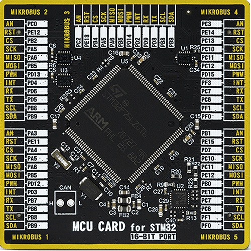
Microcontroller Overview
MCU Card / MCU
Type
8th Generation
Architecture
ARM Cortex-M7
MCU Memory (KB)
1024
Silicon Vendor
STMicroelectronics
Pin count
144
RAM (Bytes)
327680
Used MCU Pins
mikroBUS™ mapper
Take a closer look
Click board™ Schematic

Step by step
Project assembly

Start by selecting your development board and Click board™. Begin with the UNI-DS v8 as your development board.


Track your results in real time
Application Output
1. Application Output - In Debug mode, the 'Application Output' window enables real-time data monitoring, offering direct insight into execution results. Ensure proper data display by configuring the environment correctly using the provided tutorial.

2. UART Terminal - Use the UART Terminal to monitor data transmission via a USB to UART converter, allowing direct communication between the Click board™ and your development system. Configure the baud rate and other serial settings according to your project's requirements to ensure proper functionality. For step-by-step setup instructions, refer to the provided tutorial.

3. Plot Output - The Plot feature offers a powerful way to visualize real-time sensor data, enabling trend analysis, debugging, and comparison of multiple data points. To set it up correctly, follow the provided tutorial, which includes a step-by-step example of using the Plot feature to display Click board™ readings. To use the Plot feature in your code, use the function: plot(*insert_graph_name*, variable_name);. This is a general format, and it is up to the user to replace 'insert_graph_name' with the actual graph name and 'variable_name' with the parameter to be displayed.

Software Support
Library Description
This library contains API for 6DOF IMU 7 Click driver.
Key functions:
c6dofimu7_get_gyro_data- This function reads gyroscope axis data and configures the gyro axis structc6dofimu7_get_accel_data- This function reads accelerometer axis data and configures the accel axis structc6dofimu7_get_temp_data- This function reads and returns temperature data
Open Source
Code example
The complete application code and a ready-to-use project are available through the NECTO Studio Package Manager for direct installation in the NECTO Studio. The application code can also be found on the MIKROE GitHub account.
/*!
 * \file
 * \brief 6DofImu7 Click example
 *
 * # Description
 * This example showcases how to initialize and configure the logger and Click modules and read
 * and display temperature measurements and axis data from the gyroscope and accelerometer.
 *
 * The demo application is composed of two sections :
 *
 * ## Application Init
 * This function initializes and configures the logger and Click modules.
 *
 * ## Application Task
 * This function reads and displays accelerometer, gyroscope and temperature data every second.
 *
 * \author MikroE Team
 *
 */
// ------------------------------------------------------------------- INCLUDES

#include "board.h"
#include "log.h"
#include "c6dofimu7.h"

// ------------------------------------------------------------------ VARIABLES

static c6dofimu7_t c6dofimu7;
static log_t logger;
static c6dofimu7_axis_t gyro;
static c6dofimu7_axis_t accel;

// ------------------------------------------------------ APPLICATION FUNCTIONS

void application_init ( )
{
    log_cfg_t log_cfg;
    c6dofimu7_cfg_t cfg;

    /**
     * Logger initialization.
     * Default baud rate: 115200
     * Default log level: LOG_LEVEL_DEBUG
     * @note If USB_UART_RX and USB_UART_TX
     * are defined as HAL_PIN_NC, you will
     * need to define them manually for log to work.
     * See @b LOG_MAP_USB_UART macro definition for detailed explanation.
     */
    LOG_MAP_USB_UART( log_cfg );
    log_init( &logger, &log_cfg );
    log_info( &logger, "---- Application Init ----" );

    //  Click initialization.

    c6dofimu7_cfg_setup( &cfg );
    C6DOFIMU7_MAP_MIKROBUS( cfg, MIKROBUS_1 );
    c6dofimu7_init( &c6dofimu7, &cfg );
    c6dofimu7_default_cfg( &c6dofimu7 );
}

void application_task ( )
{
    float temperature;

    c6dofimu7_get_gyro_data( &c6dofimu7, &gyro, C6DOFIMU7_GYRO_SENSITIVITY );

    log_printf( &logger, " * Gyro_X: %.5f * \r\n", gyro.x_axis );
    log_printf( &logger, " * Gyro_Y: %.5f * \r\n", gyro.y_axis );
    log_printf( &logger, " * Gyro_Z: %.5f * \r\n", gyro.z_axis );
    log_printf( &logger, " ---------------------------- \r\n" );

    c6dofimu7_get_accel_data( &c6dofimu7, &accel, C6DOFIMU7_ACCEL_SENSITIVITY );

    log_printf( &logger, " * Accel_X: %.5f * \r\n", accel.x_axis );
    log_printf( &logger, " * Accel_Y: %.5f * \r\n", accel.y_axis );
    log_printf( &logger, " * Accel_Z: %.5f * \r\n", accel.z_axis );
    log_printf( &logger, " ---------------------------- \r\n" );

    temperature = c6dofimu7_get_temp_data( &c6dofimu7, C6DOFIMU7_TEMPERATURE_SENSITIVITY,
                                                       C6DOFIMU7_TEMPERATURE_OFFSET );

    log_printf( &logger, " * Temperature: %.5f C * \r\n\r\n", temperature );
    Delay_ms ( 1000 );
}

int main ( void )
{
    /* Do not remove this line or clock might not be set correctly. */
    #ifdef PREINIT_SUPPORTED
    preinit();
    #endif

    application_init( );

    for ( ; ; )
    {
        application_task( );
    }

    return 0;
}

// ------------------------------------------------------------------------ END


