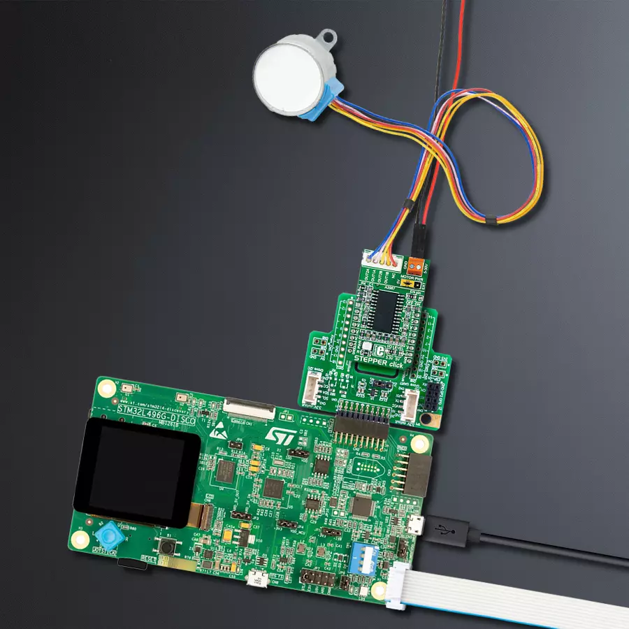
Make controlling a bipolar stepper motor easier and more efficient with A3967 and STM32L496AG
Ideal solution for small stepping motors in office automation, as well as commercial and industrial equipment
Published Jul 22, 2025
Click board™
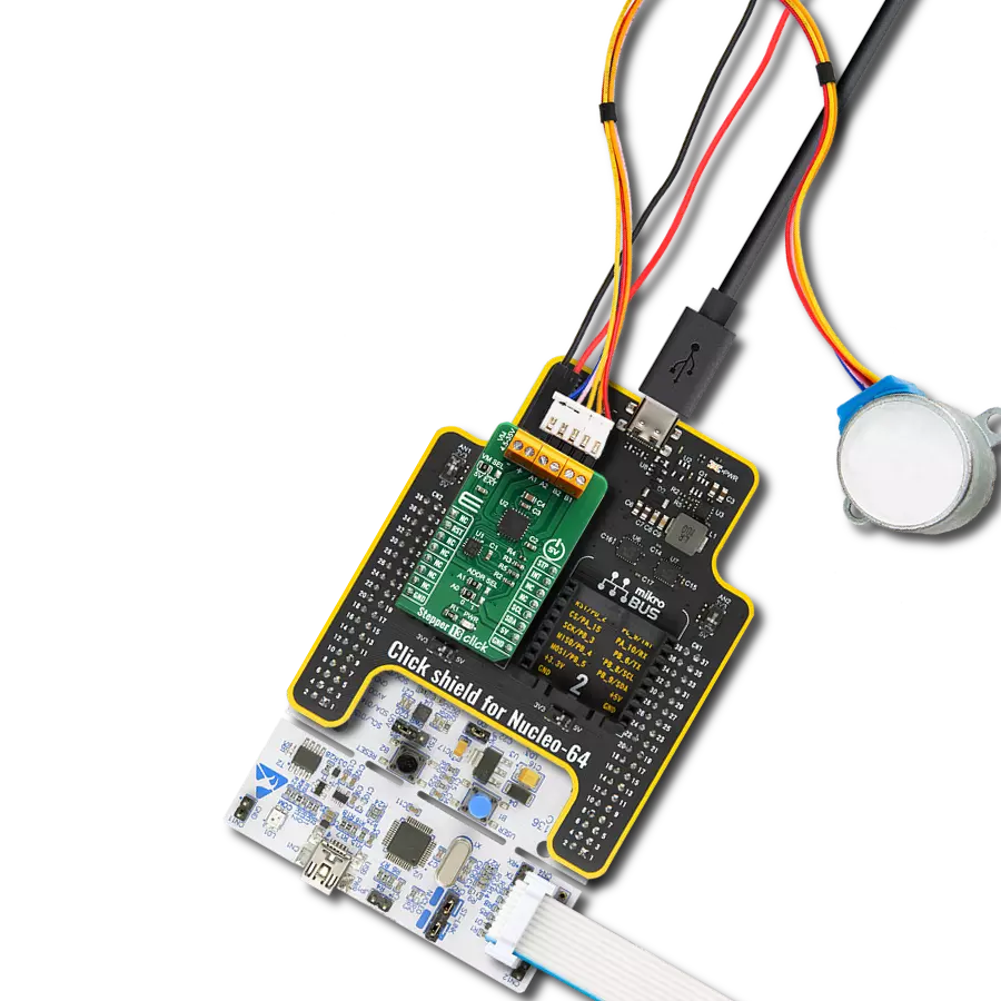
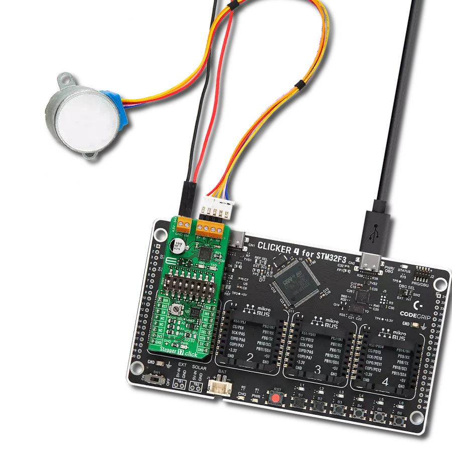
STEPPER Click
Dev. board
Discovery kit with STM32L496AG MCU
Compiler
NECTO Studio
MCU
STM32L496AG
Control the bipolar stepper motor's movement in both directions using simple step control inputs from your host MCU
A
A
Hardware Overview
How does it work?
Stepper Click is based on the A3967, a micro-stepping driver with a translator from Allegro Microsystems. This highly integrated IC offers a simple bipolar stepper motor control interface, thanks to the integrated translator section. This section controls the output drivers, providing smooth action of the stepper motor. By controlling the current intensity throughout the rotation cycle, a constant torque is achieved for every position. The current regulator uses an internal comparator, DA converter, and external sensing resistor. The sensing resistor value determines the maximum current during the operation, limiting it to 568mA when using 5V or 350mA when using 3.3V as the reference voltage. Additional features of the Stepper Click include under-voltage, shoot-through, and thermal protection so the Click board™ can operate reliably. Its input voltage range of up to 25V can drive a wide range of stepper motors with
up to 750mA max. The Click board™ offers a choice to use a power source for driving the motor: one is the external voltage routed to the input connector, while the other is a 5V power rail from the mikroBUS™. While using the external connector, the voltage of the external power supply should remain below 25V. Selection between the external power supply and 5V rail from the mikroBUS™ can be made by moving the jumper labeled as MOTOR PWR to either the 5V position or EXT position. The stepper motor can be connected via the disconnectable crimp style XH connector with 2.5mm pitch, usually found on many small-size stepper motors. This header is optional and comes unsoldered in case some other type of header or connector needs to be used instead. Stepper Click uses GPIO pins to communicate with the host MCU. A LOW to HIGH transition on the STP pin will perform one rotational step. The logic
state on the DIR pin controls the direction of the rotation. The step size is determined by two pins: MS1 and MS2. It is possible to work with full steps (using two phases), half, quarter, and eighth steps. The SMD jumper labeled as the EN pin can be used to route the #EN pin of the IC to the EN pin of the mikroBUS™. This allows the host MCU to turn the A3967 ON or OFF. By default, this jumper is positioned to route the #EN pin to the GND directly, permanently enabling the IC. This Click board™ can operate with either 3.3V or 5V logic voltage levels selected via the I/O LEVEL jumper. This way, both 3.3V and 5V capable MCUs can use the communication lines properly. Also, this Click board™ comes equipped with a library containing easy-to-use functions and an example code that can be used as a reference for further development.

Features overview
Development board
The 32L496GDISCOVERY Discovery kit serves as a comprehensive demonstration and development platform for the STM32L496AG microcontroller, featuring an Arm® Cortex®-M4 core. Designed for applications that demand a balance of high performance, advanced graphics, and ultra-low power consumption, this kit enables seamless prototyping for a wide range of embedded solutions. With its innovative energy-efficient
architecture, the STM32L496AG integrates extended RAM and the Chrom-ART Accelerator, enhancing graphics performance while maintaining low power consumption. This makes the kit particularly well-suited for applications involving audio processing, graphical user interfaces, and real-time data acquisition, where energy efficiency is a key requirement. For ease of development, the board includes an onboard ST-LINK/V2-1
debugger/programmer, providing a seamless out-of-the-box experience for loading, debugging, and testing applications without requiring additional hardware. The combination of low power features, enhanced memory capabilities, and built-in debugging tools makes the 32L496GDISCOVERY kit an ideal choice for prototyping advanced embedded systems with state-of-the-art energy efficiency.

Microcontroller Overview
MCU Card / MCU

Architecture
ARM Cortex-M4
MCU Memory (KB)
1024
Silicon Vendor
STMicroelectronics
Pin count
169
RAM (Bytes)
327680
You complete me!
Accessories
The 28BYJ-48 is an adaptable 5VDC stepper motor with a compact design, ideal for various applications. It features four phases, a speed variation ratio of 1/64, and a stride angle of 5.625°/64 steps, allowing precise control. The motor operates at a frequency of 100Hz and has a DC resistance of 50Ω ±7% at 25°C. It boasts an idle in-traction frequency greater than 600Hz and an idle out-traction frequency exceeding 1000Hz, ensuring reliability in different scenarios. With a self-positioning torque and in-traction torque both exceeding 34.3mN.m at 120Hz, the 28BYJ-48 offers robust performance. Its friction torque ranges from 600 to 1200 gf.cm, while the pull-in torque is 300 gf.cm. This motor makes a reliable and efficient choice for your stepper motor needs.

Used MCU Pins
mikroBUS™ mapper
Take a closer look
Click board™ Schematic

Step by step
Project assembly

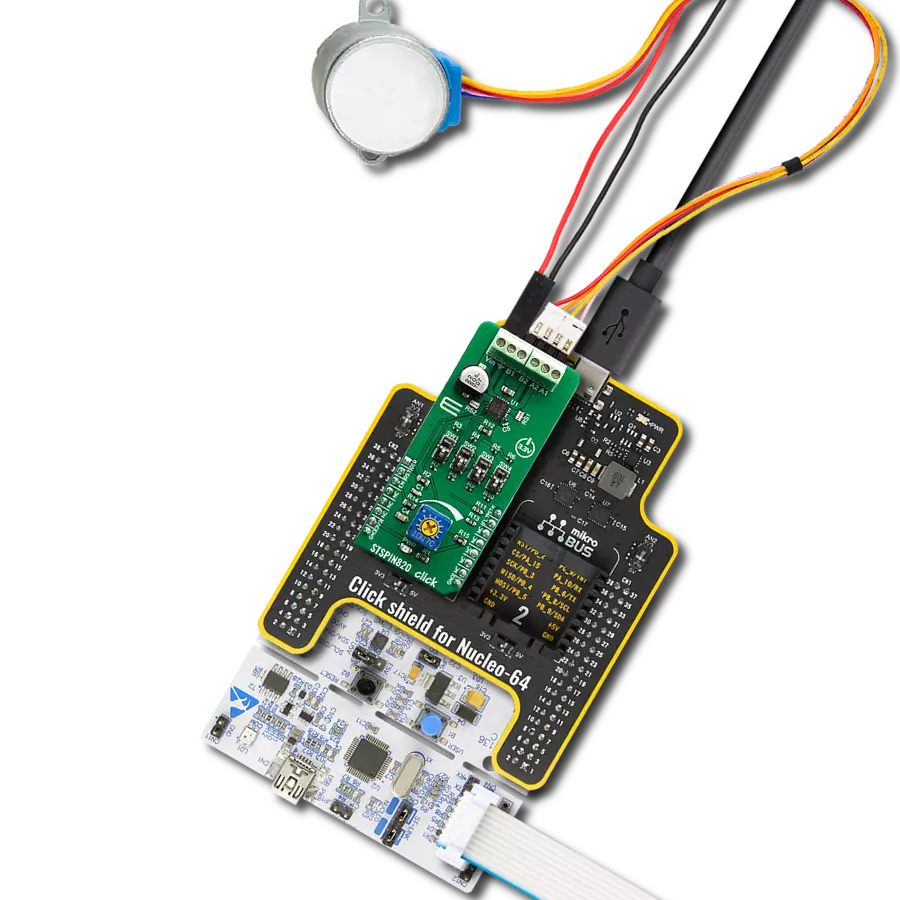
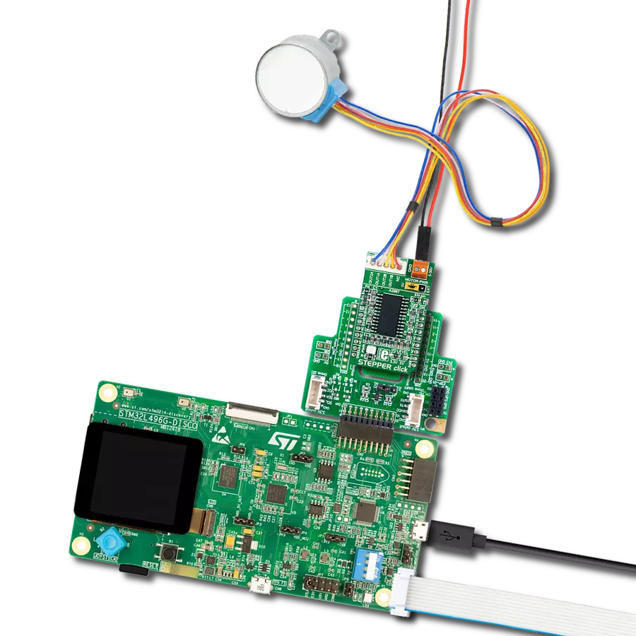
Start by selecting your development board and Click board™. Begin with the Discovery kit with STM32L496AG MCU as your development board.


Software Support
Library Description
This library contains API for STEPPER Click driver.
Key functions:
stepper_set_step_mode- This function sets the step mode resolution settingsstepper_set_direction- This function sets the motor direction by setting the DIR pin logic statestepper_drive_motor- This function drives the motor for the specific number of steps at the selected speed
Open Source
Code example
The complete application code and a ready-to-use project are available through the NECTO Studio Package Manager for direct installation in the NECTO Studio. The application code can also be found on the MIKROE GitHub account.
/*!
 * @file main.c
 * @brief Stepper Click Example.
 *
 * # Description
 * This example demonstrates the use of the Stepper Click board by driving the
 * motor in both directions for a desired number of steps.
 *
 * The demo application is composed of two sections :
 *
 * ## Application Init
 * Initializes the driver and performs the Click default configuration.
 *
 * ## Application Task
 * Drives the motor clockwise for 64 full steps and then counter-clockiwse for 128 half
 * steps with 2 seconds delay before changing the direction. All data is being logged on
 * the USB UART where you can track the program flow.
 *
 * @note
 * Step Motor 5v [MIKROE-1530] is a fully compatible stepper motor for this Click board:
 * https://www.mikroe.com/step-motor-5v
 *
 * @author Stefan Filipovic
 *
 */

#include "board.h"
#include "log.h"
#include "stepper.h"

static stepper_t stepper;   /**< Stepper Click driver object. */
static log_t logger;    /**< Logger object. */

void application_init ( void )
{
    log_cfg_t log_cfg;  /**< Logger config object. */
    stepper_cfg_t stepper_cfg;  /**< Click config object. */

    /**
     * Logger initialization.
     * Default baud rate: 115200
     * Default log level: LOG_LEVEL_DEBUG
     * @note If USB_UART_RX and USB_UART_TX
     * are defined as HAL_PIN_NC, you will
     * need to define them manually for log to work.
     * See @b LOG_MAP_USB_UART macro definition for detailed explanation.
     */
    LOG_MAP_USB_UART( log_cfg );
    log_init( &logger, &log_cfg );
    log_info( &logger, " Application Init " );

    // Click initialization.
    stepper_cfg_setup( &stepper_cfg );
    STEPPER_MAP_MIKROBUS( stepper_cfg, MIKROBUS_1 );
    if ( DIGITAL_OUT_UNSUPPORTED_PIN == stepper_init( &stepper, &stepper_cfg ) )
    {
        log_error( &logger, " Communication init." );
        for ( ; ; );
    }

    stepper_default_cfg ( &stepper );

    log_info( &logger, " Application Task " );
}

void application_task ( void )
{
    log_printf ( &logger, " Move 64 full steps clockwise \r\n\n" );
    stepper_set_step_mode ( &stepper, STEPPER_MODE_FULL_STEP );
    stepper_set_direction ( &stepper, STEPPER_DIR_CW );
    stepper_drive_motor ( &stepper, 64, STEPPER_SPEED_FAST );
    Delay_ms ( 1000 );
    Delay_ms ( 1000 );

    log_printf ( &logger, " Move 128 half steps counter-clockwise \r\n\n" );
    stepper_set_step_mode ( &stepper, STEPPER_MODE_HALF_STEP );
    stepper_set_direction ( &stepper, STEPPER_DIR_CCW );
    stepper_drive_motor ( &stepper, 128, STEPPER_SPEED_VERY_FAST );
    Delay_ms ( 1000 );
    Delay_ms ( 1000 );
}

int main ( void )
{
    /* Do not remove this line or clock might not be set correctly. */
    #ifdef PREINIT_SUPPORTED
    preinit();
    #endif

    application_init( );

    for ( ; ; )
    {
        application_task( );
    }

    return 0;
}

// ------------------------------------------------------------------------ END
Additional Support
Resources
Category:Stepper