Deliver smooth, silent motion of the bipolar stepper motors with TMC2660 and STM32G474RE
Universal stepper driver for two-phase bipolar motors with up to 4A motor current per coil
Published Nov 08, 2024
Click board™
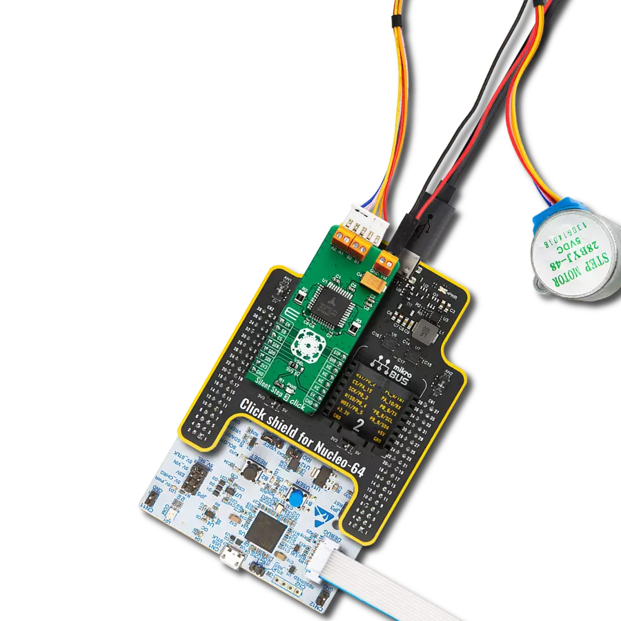
Silent Step 3 Click
Dev. board
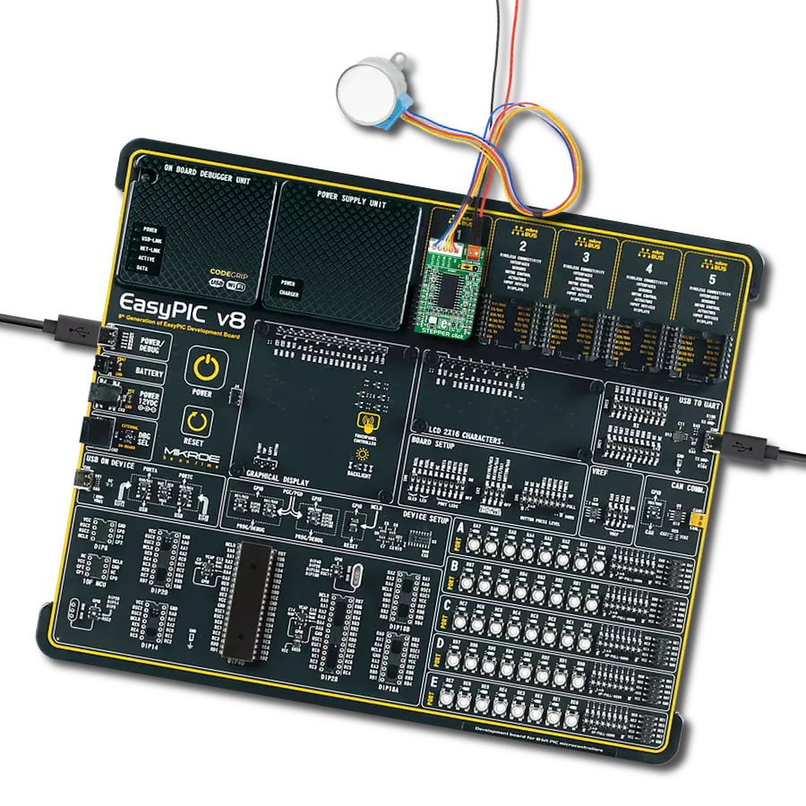
Nucleo 64 with STM32G474RE MCU
Compiler
NECTO Studio
MCU
STM32G474RE
Leap forward in stepper motor control technology, combining high power and advanced features for smooth and silent operation
A
A
Hardware Overview
How does it work?
Silent Step 3 Click is based on the TMC2660, a highly integrated bipolar step motor power driver from Analog Devices. As mentioned, this device has many different features, allowing the driver to be used almost autonomously. Two control interfaces exist: the SPI serial interface and the STEP/DIR interface. The SPI interface writes control information to the chip and returns status information. This interface must be used to initialize the parameters and modes necessary to enable driving the motor. The motion of the motor can be controlled by using the STEP and DIR signals or through the SPI interface alone. Technologies, such as stallGuard2™, spreadCycle™, coolStep™, spreadCycle™, and microPlayer™, help to achieve high autonomy and smooth motion of the driven motor, even by using the STEP and DIR input pins to set the direction and step propagation. The internal micro step table maps the sine function from 0° to 90°. Symmetries allow mapping of the sine and cosine functions from 0° to 360° with this table. The TMC2660 supports two motor driver control modes: STEP/DIR and SPI modes. STEP/DIR mode is also referred to as the legacy mode. The device is operated similarly to other pin-driven step motor controllers/drivers – the step propagation is controlled by pulses on the STEP
input, and the DIR pin determines the direction. In SPI mode, the user can directly access the motor's current sign and magnitude by setting the parameters in the DRVCTRL Register. All working parameters can be configured and controlled via the SPI interface in both modes. Also, the power and thermal data can be returned to the MCU for further analysis and optimization. In STEP/DIR mode, the microPlyer STEP pulse interpolator brings the smooth motor operation of high-resolution micro-stepping to applications originally designed for coarser stepping and reduces pulse bandwidth. MicroPlyer produces 16 micro steps at 256x resolution for each active edge on the STP pin of the Silent Step 3 Click. The currents through both motor coils are controlled using choppers, which work independently of each other. Two chopper modes are available: a new high-performance chopper algorithm called spreadCycle and a proven constant off-time chopper mode. The constant off-time mode cycles through three phases: on, fast decay, and slow decay. The spreadCycle mode cycles through four phases: on, slow decay, fast decay, and a second slow decay. The current through the motor coils has to be measured to achieve all the previously mentioned features. Because of the high power output of the
TMC2660, external shunt resistors are required. Therefore, the Silent Step 3 Click has onboard carefully selected, low-inductance type 0.1 Ohm shunt resistors. This minimizes measurement imperfections caused by the switching spikes from the MOSFET bridges, for example, and maximizes the efficiency of the TMC2660. The STEP, DIR, and ENN pins of the TMC2660 are directly routed to the mikroBUS™ pins PWM, INT, and AN and marked as STP, DIR, and EN, respectively. The digital I/O pins' logic levels are easily adjustable by setting the desired voltage to the VCC_IO pin. Therefore, the interface logic level on the Silent Step 3 click can be easily configured for 3.3 V or 5 V logic by moving the VSEL jumper to the respective voltage, which allows both 3.3V and 5V MCUs to be interfaced with this Click board™. The power supply for the bipolar stepper motor can be connected to the terminal's VM and GND inputs. The connected voltage should stay within the range between 9V and 29V. The rest of the terminals allow bipolar stepper motor coils to be connected: A1 and A2 terminal inputs connect the first coil, while the B1 and B2 inputs connect the second motor coil.

Features overview
Development board
Nucleo-64 with STM32G474R MCU offers a cost-effective and adaptable platform for developers to explore new ideas and prototype their designs. This board harnesses the versatility of the STM32 microcontroller, enabling users to select the optimal balance of performance and power consumption for their projects. It accommodates the STM32 microcontroller in the LQFP64 package and includes essential components such as a user LED, which doubles as an ARDUINO® signal, alongside user and reset push-buttons, and a 32.768kHz crystal oscillator for precise timing operations. Designed with expansion and flexibility in mind, the Nucleo-64 board features an ARDUINO® Uno V3 expansion connector and ST morpho extension pin
headers, granting complete access to the STM32's I/Os for comprehensive project integration. Power supply options are adaptable, supporting ST-LINK USB VBUS or external power sources, ensuring adaptability in various development environments. The board also has an on-board ST-LINK debugger/programmer with USB re-enumeration capability, simplifying the programming and debugging process. Moreover, the board is designed to simplify advanced development with its external SMPS for efficient Vcore logic supply, support for USB Device full speed or USB SNK/UFP full speed, and built-in cryptographic features, enhancing both the power efficiency and security of projects. Additional connectivity is
provided through dedicated connectors for external SMPS experimentation, a USB connector for the ST-LINK, and a MIPI® debug connector, expanding the possibilities for hardware interfacing and experimentation. Developers will find extensive support through comprehensive free software libraries and examples, courtesy of the STM32Cube MCU Package. This, combined with compatibility with a wide array of Integrated Development Environments (IDEs), including IAR Embedded Workbench®, MDK-ARM, and STM32CubeIDE, ensures a smooth and efficient development experience, allowing users to fully leverage the capabilities of the Nucleo-64 board in their projects.

Microcontroller Overview
MCU Card / MCU

Architecture
ARM Cortex-M4
MCU Memory (KB)
512
Silicon Vendor
STMicroelectronics
Pin count
64
RAM (Bytes)
128k
You complete me!
Accessories
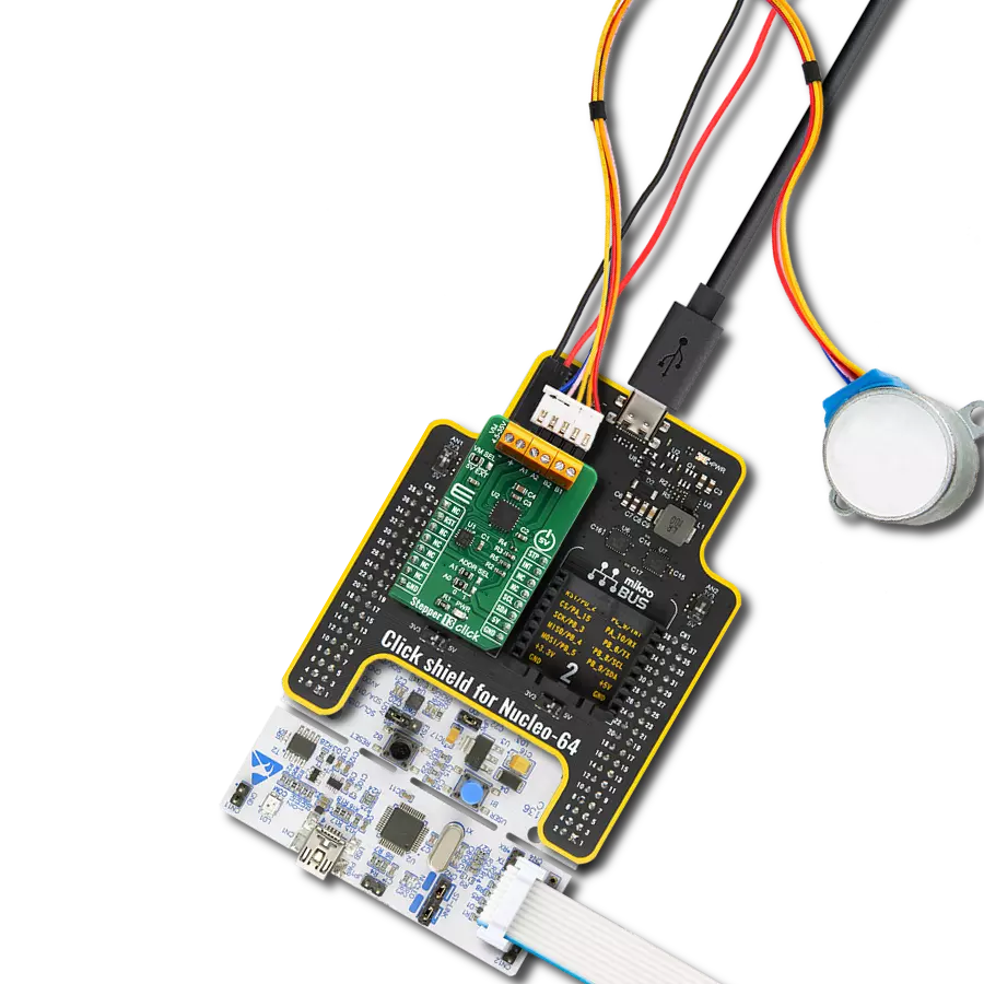
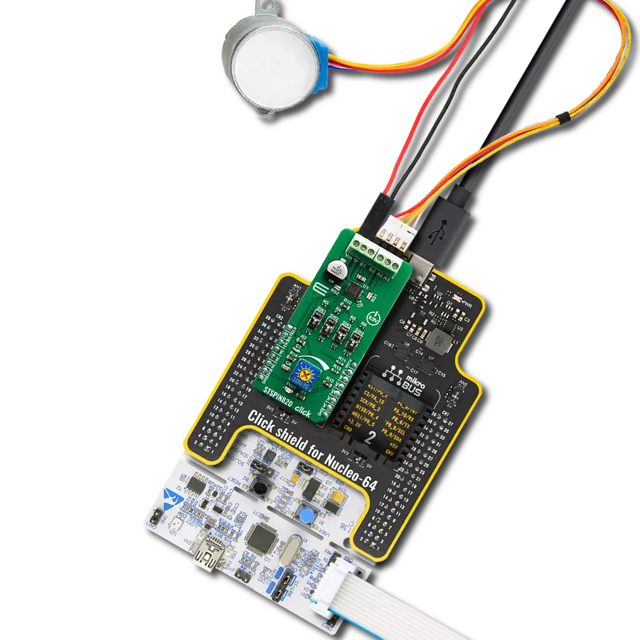
Click Shield for Nucleo-64 comes equipped with two proprietary mikroBUS™ sockets, allowing all the Click board™ devices to be interfaced with the STM32 Nucleo-64 board with no effort. This way, Mikroe allows its users to add any functionality from our ever-growing range of Click boards™, such as WiFi, GSM, GPS, Bluetooth, ZigBee, environmental sensors, LEDs, speech recognition, motor control, movement sensors, and many more. More than 1537 Click boards™, which can be stacked and integrated, are at your disposal. The STM32 Nucleo-64 boards are based on the microcontrollers in 64-pin packages, a 32-bit MCU with an ARM Cortex M4 processor operating at 84MHz, 512Kb Flash, and 96KB SRAM, divided into two regions where the top section represents the ST-Link/V2 debugger and programmer while the bottom section of the board is an actual development board. These boards are controlled and powered conveniently through a USB connection to program and efficiently debug the Nucleo-64 board out of the box, with an additional USB cable connected to the USB mini port on the board. Most of the STM32 microcontroller pins are brought to the IO pins on the left and right edge of the board, which are then connected to two existing mikroBUS™ sockets. This Click Shield also has several switches that perform functions such as selecting the logic levels of analog signals on mikroBUS™ sockets and selecting logic voltage levels of the mikroBUS™ sockets themselves. Besides, the user is offered the possibility of using any Click board™ with the help of existing bidirectional level-shifting voltage translators, regardless of whether the Click board™ operates at a 3.3V or 5V logic voltage level. Once you connect the STM32 Nucleo-64 board with our Click Shield for Nucleo-64, you can access hundreds of Click boards™, working with 3.3V or 5V logic voltage levels.

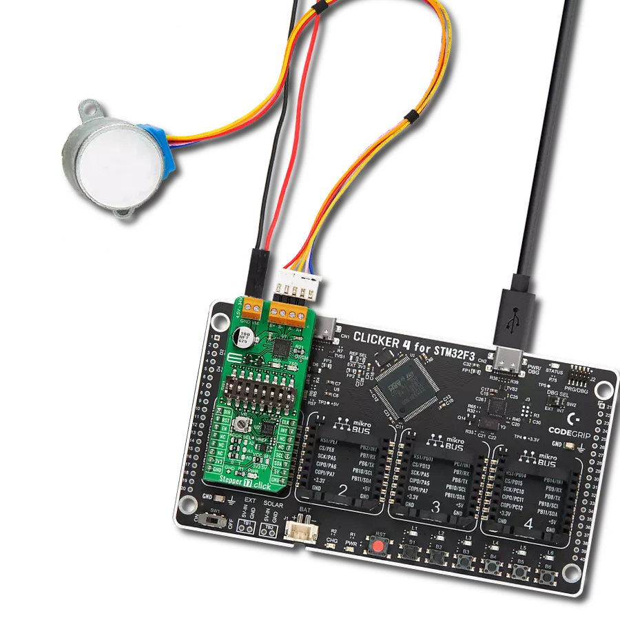
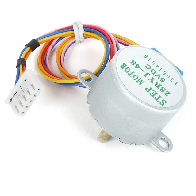
The 28BYJ-48 is an adaptable 5VDC stepper motor with a compact design, ideal for various applications. It features four phases, a speed variation ratio of 1/64, and a stride angle of 5.625°/64 steps, allowing precise control. The motor operates at a frequency of 100Hz and has a DC resistance of 50Ω ±7% at 25°C. It boasts an idle in-traction frequency greater than 600Hz and an idle out-traction frequency exceeding 1000Hz, ensuring reliability in different scenarios. With a self-positioning torque and in-traction torque both exceeding 34.3mN.m at 120Hz, the 28BYJ-48 offers robust performance. Its friction torque ranges from 600 to 1200 gf.cm, while the pull-in torque is 300 gf.cm. This motor makes a reliable and efficient choice for your stepper motor needs.
Used MCU Pins
mikroBUS™ mapper
Take a closer look
Click board™ Schematic

Step by step
Project assembly
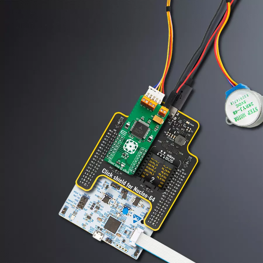
Start by selecting your development board and Click board™. Begin with the Nucleo 64 with STM32G474RE MCU as your development board.


Software Support
Library Description
This library contains API for Silent Step 3 Click driver.
Key functions:
silentstep3_set_step_mode- This function sets the microstep resolution bits in DRVCTRL registersilentstep3_set_direction- This function sets the motor direction by setting the DIR pin logic statesilentstep3_drive_motor- This function drives the motor for the specific number of steps at the selected speed
Open Source
Code example
The complete application code and a ready-to-use project are available through the NECTO Studio Package Manager for direct installation in the NECTO Studio. The application code can also be found on the MIKROE GitHub account.
/*!
 * @file main.c
 * @brief Silent Step 3 Click example
 *
 * # Description
 * This example demonstrates the use of the Silent Step 3 Click board by driving the
 * motor in both directions for a desired number of steps.
 *
 * The demo application is composed of two sections :
 *
 * ## Application Init
 * Initializes the driver and performs the Click default configuration.
 *
 * ## Application Task
 * Drives the motor clockwise for 200 full steps and then counter-clockiwse for 200 half
 * steps and 400 quarter steps with 2 seconds delay on driving mode change. All data is
 * being logged on the USB UART where you can track the program flow.
 *
 * @author Stefan Filipovic
 *
 */

#include "board.h"
#include "log.h"
#include "silentstep3.h"

static silentstep3_t silentstep3;
static log_t logger;

void application_init ( void )
{
    log_cfg_t log_cfg;  /**< Logger config object. */
    silentstep3_cfg_t silentstep3_cfg;  /**< Click config object. */

    /**
     * Logger initialization.
     * Default baud rate: 115200
     * Default log level: LOG_LEVEL_DEBUG
     * @note If USB_UART_RX and USB_UART_TX
     * are defined as HAL_PIN_NC, you will
     * need to define them manually for log to work.
     * See @b LOG_MAP_USB_UART macro definition for detailed explanation.
     */
    LOG_MAP_USB_UART( log_cfg );
    log_init( &logger, &log_cfg );
    log_info( &logger, " Application Init " );

    // Click initialization.
    silentstep3_cfg_setup( &silentstep3_cfg );
    SILENTSTEP3_MAP_MIKROBUS( silentstep3_cfg, MIKROBUS_1 );
    if ( SPI_MASTER_ERROR == silentstep3_init( &silentstep3, &silentstep3_cfg ) )
    {
        log_error( &logger, " Communication init." );
        for ( ; ; );
    }

    if ( SILENTSTEP3_ERROR == silentstep3_default_cfg ( &silentstep3 ) )
    {
        log_error( &logger, " Default configuration." );
        for ( ; ; );
    }

    log_info( &logger, " Application Task " );
}

void application_task ( void )
{
    log_printf ( &logger, " Move 200 full steps clockwise, speed: slow\r\n\n" );
    silentstep3_set_direction ( &silentstep3, SILENTSTEP3_DIR_CW );
    silentstep3_set_step_mode ( &silentstep3, SILENTSTEP3_MODE_FULL_STEP );
    silentstep3_drive_motor ( &silentstep3, 200, SILENTSTEP3_SPEED_SLOW );
    Delay_ms ( 1000 );
    Delay_ms ( 1000 );

    log_printf ( &logger, " Move 200 half steps counter-clockwise, speed: medium\r\n\n" );
    silentstep3_set_direction ( &silentstep3, SILENTSTEP3_DIR_CCW );
    silentstep3_set_step_mode ( &silentstep3, SILENTSTEP3_MODE_HALF_STEP );
    silentstep3_drive_motor ( &silentstep3, 200, SILENTSTEP3_SPEED_MEDIUM );
    Delay_ms ( 1000 );
    Delay_ms ( 1000 );

    log_printf ( &logger, " Move 400 quarter steps counter-clockwise, speed: fast\r\n\n" );
    silentstep3_set_direction ( &silentstep3, SILENTSTEP3_DIR_CCW );
    silentstep3_set_step_mode ( &silentstep3, SILENTSTEP3_MODE_QUARTER_STEP );
    silentstep3_drive_motor ( &silentstep3, 400, SILENTSTEP3_SPEED_FAST );
    Delay_ms ( 1000 );
    Delay_ms ( 1000 );
}

int main ( void )
{
    /* Do not remove this line or clock might not be set correctly. */
    #ifdef PREINIT_SUPPORTED
    preinit();
    #endif

    application_init( );

    for ( ; ; )
    {
        application_task( );
    }

    return 0;
}

// ------------------------------------------------------------------------ END
Additional Support
Resources
Category:Stepper