Maximize efficiency in circuit calibration and tuning with AD5231 and STM32L496AG
Calibration at the speed of light
Published Jul 22, 2025
Click board™
DIGI POT 3 Click
Dev. board
Discovery kit with STM32L496AG MCU
Compiler
NECTO Studio
MCU
STM32L496AG
Replace traditional analog counterparts with our digital potentiometer, ensuring longevity, reliability, and adaptability for evolving applications
A
A
Hardware Overview
How does it work?
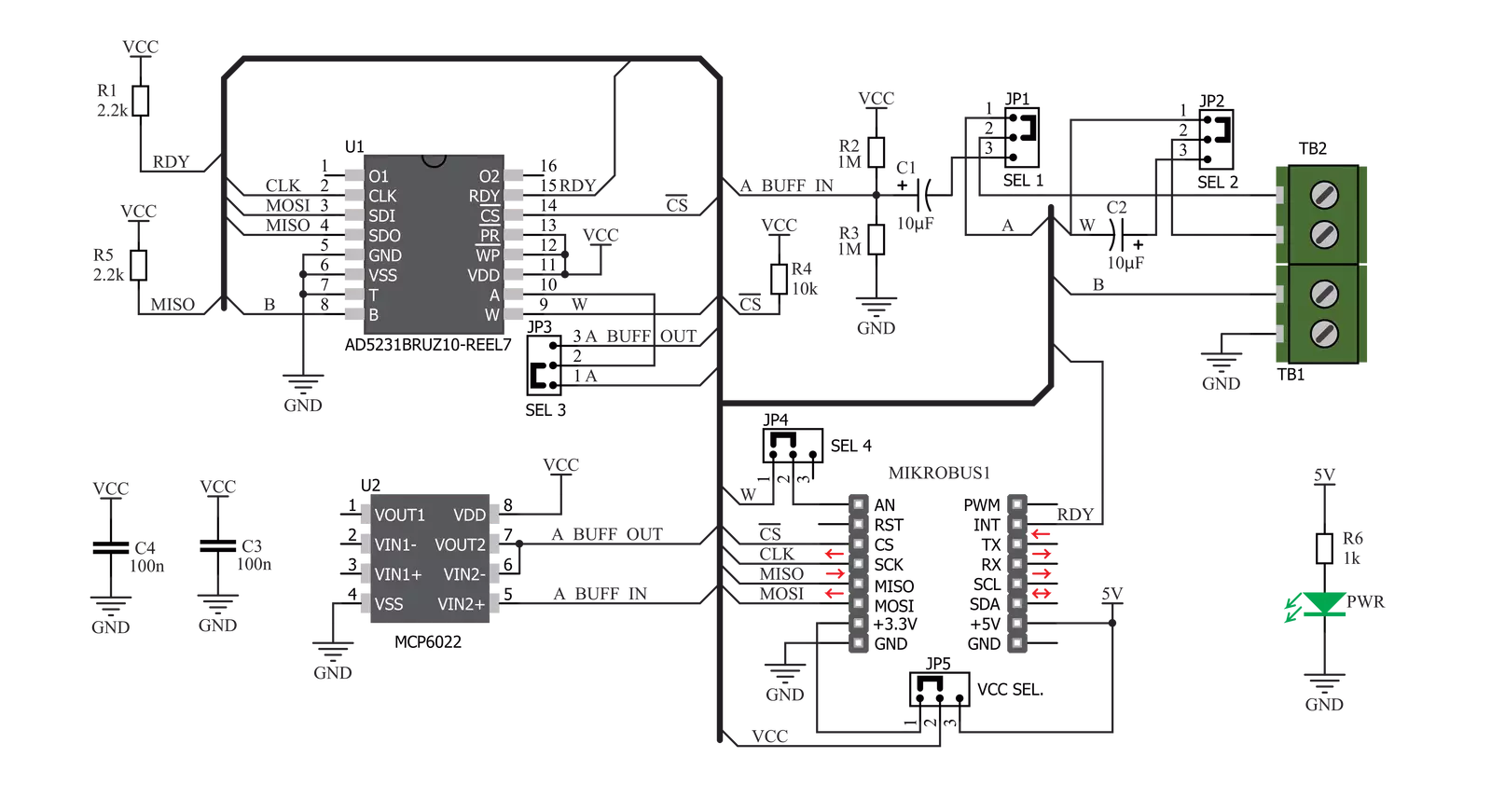
DIGI POT 3 Click is based on the AD5231, a 1024-position (10bit) digital potentiometer with a non-volatile memory (EEMEM) from Analog Devices. As mentioned, this digital potentiometer has many features, making it a superior choice over classic mechanical potentiometers. It offers solid state reliability, high precision, additional storage of non-volatile (NV) memory cells, and, most importantly - it can be digitally controlled by an MCU via the high-speed SPI interface, with its pins routed to the mikroBUS™. Analog Devices Inc. offers several sub-types of the same IC, but the DIGI POT 3 click uses the one labeled AD5231BRUZ10, meaning it has 10KΩ of resistance between the potentiometer endpoints. One of its distinctive features is to refresh its wiper register (called RDAC in the device datasheet) after the power is on, making it possible to restore the wiper position on power-up, just like the mechanical counterpart. The wiper position register (RDAC) is not automatically written to the EEMEM because this type of memory has a limited number of write cycles, which is the limitation of the technology itself. For this reason, once the position has been established, it can be stored in EEMEM by a command (Command 0x2 - Store RDAC setting to EEMEM). The AD5231 IC is factory pre-programmed to set the wiper at the middle position after the power-on, but this can be overwritten by storing a custom position with the command mentioned above. Besides storing the RDAC register to the EEMEM, it is possible to store 14 more words, each 16 bits long. This EEMEM area can be used for any purpose - lookup tables, data for other components, or system identification information. Writing to EEMEM takes some time, and the AD5231 IC is non-
responsive. This time is about 25ms, and the end of this operation is signaled by the RDY pin of the AD5231 IC, routed to the INT pin of the mikroBUS™ - labeled as the RDY. When the read-to or write from the EEMEM cycle is done, this pin pulses to a LOW logic level. It is otherwise pulled to a HIGH logic level by an onboard pull-up resistor. For the complete list of commands and addresses, please refer to the AD5231 datasheet. However, MikroElektronika provides a library containing functions compatible with the MIKROE compilers, which can be used for simplified DIGI POT 3 Click programming. The library also contains an example application that demonstrates its use. This example application can be used as a reference for custom designs. The Click board™ is equipped with edge screw terminals, which connect the Click board™ to the external electrical circuit. They offer a secure connection to the external electrical circuit. A small print of a potentiometer electrical symbol illustrates how to connect these terminals properly: Inputs labeled as A and B are the endpoints of the digital potentiometer, while W is the wiper. Lastly, the GND symbol connects the circuit's ground where the potentiometer will be used. DIGI POT 3 Click allows using of both unipolar and bipolar signals. The potential across the positive and the negative power supply pins define the boundary conditions for a proper digital potentiometer operation. The internal forward-biased diodes clamp supply signals on the A, B, and W terminals that exceed this range. Since this Click board™ is intended to be used on the mikroBUS™, the power supply voltage of the AD5231 is +3.3V or +5V, selectable by an onboard SMD jumper labeled as VCC SEL. This makes working with the voltage range between 0
and VCC possible. By utilizing additional circuitry, it is also possible to work with the bipolar signals, which can be useful for interfacing the digit to an audio source. Since no negative power supplies are available on the mikroBUS™, the Click board™ uses the MCP6022, a rail-to-rail, 10 MHz onboard operational amplifier from Microchip, to support operation with bipolar signals. It is a non-inverting amplifier with a unity gain - a buffer. Several onboard SMD jumpers are used to route the signal so it passes through the buffer instead of being fed directly to the AD5231 IC. A group of SMD jumpers labeled as SIGNAL POLARITY is used to patch the signal to a proper route: setting all these jumpers to the LEFT position will connect the terminal inputs directly to the AD5231 IC, allowing unipolar signals ranging from 0 to VCC to be connected. Moving all these jumpers to the RIGHT position will route the input signal through the decoupling capacitor and the buffer, allowing bipolar signals to be used and introducing an offset of VCC/2. This allows the signal to swing between VCC/2 and GND for the negative half-cycle and between VCC/2 and VCC for the positive half-cycle. The offset is then removed by a decoupling capacitor at the W terminal. The SMD jumpers should be moved to the LEFT or the RIGHT position, as leaving some of them in the opposite position may render the device unresponsive. The AN pin can be used as an auxiliary wiper output if routing of the wiper back to the mikroBUS™ is required. This pin can be completely disconnected from the mikroBUS™ by moving the appropriate SMD jumper labeled as AN to the RIGHT position. This will not affect the presence of the wiper output on the output terminal.

Features overview
Development board
The 32L496GDISCOVERY Discovery kit serves as a comprehensive demonstration and development platform for the STM32L496AG microcontroller, featuring an Arm® Cortex®-M4 core. Designed for applications that demand a balance of high performance, advanced graphics, and ultra-low power consumption, this kit enables seamless prototyping for a wide range of embedded solutions. With its innovative energy-efficient
architecture, the STM32L496AG integrates extended RAM and the Chrom-ART Accelerator, enhancing graphics performance while maintaining low power consumption. This makes the kit particularly well-suited for applications involving audio processing, graphical user interfaces, and real-time data acquisition, where energy efficiency is a key requirement. For ease of development, the board includes an onboard ST-LINK/V2-1
debugger/programmer, providing a seamless out-of-the-box experience for loading, debugging, and testing applications without requiring additional hardware. The combination of low power features, enhanced memory capabilities, and built-in debugging tools makes the 32L496GDISCOVERY kit an ideal choice for prototyping advanced embedded systems with state-of-the-art energy efficiency.

Microcontroller Overview
MCU Card / MCU

Architecture
ARM Cortex-M4
MCU Memory (KB)
1024
Silicon Vendor
STMicroelectronics
Pin count
169
RAM (Bytes)
327680
Used MCU Pins
mikroBUS™ mapper
Take a closer look
Click board™ Schematic
Step by step
Project assembly

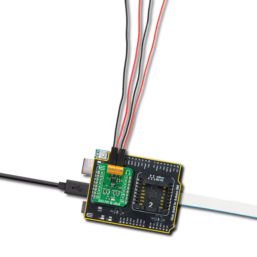
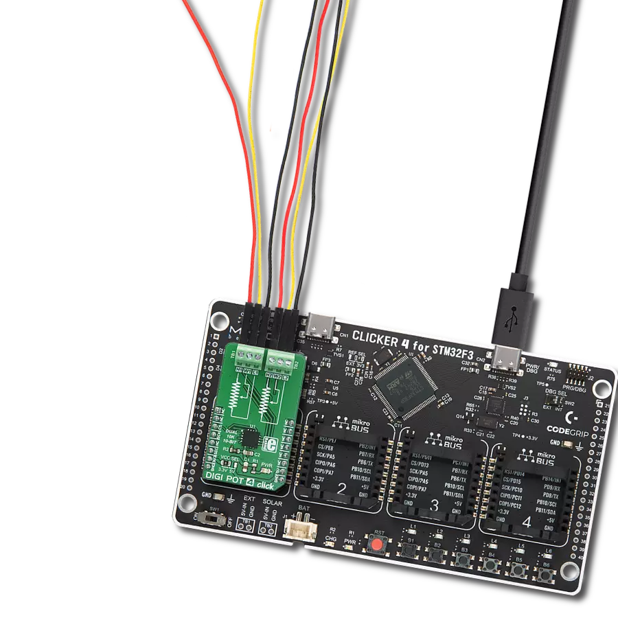
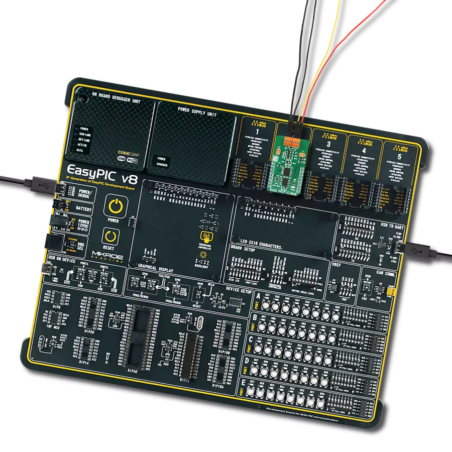
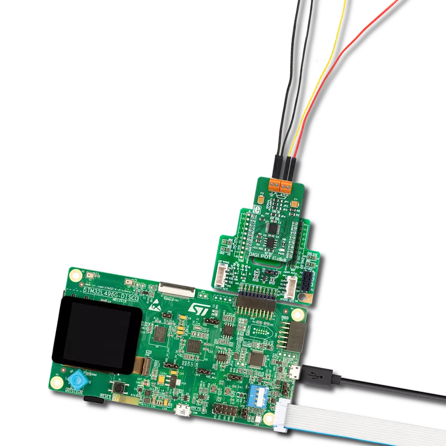
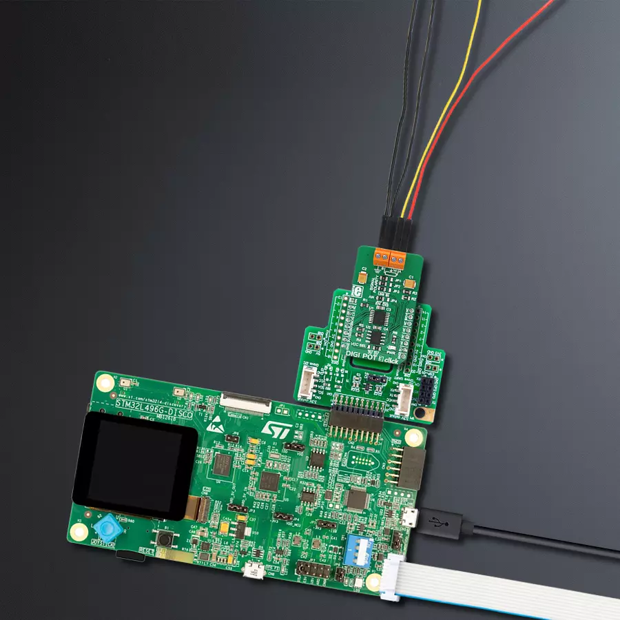
Start by selecting your development board and Click board™. Begin with the Discovery kit with STM32L496AG MCU as your development board.


Track your results in real time
Application Output
1. Application Output - In Debug mode, the 'Application Output' window enables real-time data monitoring, offering direct insight into execution results. Ensure proper data display by configuring the environment correctly using the provided tutorial.

2. UART Terminal - Use the UART Terminal to monitor data transmission via a USB to UART converter, allowing direct communication between the Click board™ and your development system. Configure the baud rate and other serial settings according to your project's requirements to ensure proper functionality. For step-by-step setup instructions, refer to the provided tutorial.

3. Plot Output - The Plot feature offers a powerful way to visualize real-time sensor data, enabling trend analysis, debugging, and comparison of multiple data points. To set it up correctly, follow the provided tutorial, which includes a step-by-step example of using the Plot feature to display Click board™ readings. To use the Plot feature in your code, use the function: plot(*insert_graph_name*, variable_name);. This is a general format, and it is up to the user to replace 'insert_graph_name' with the actual graph name and 'variable_name' with the parameter to be displayed.

Software Support
Library Description
This library contains API for DIGI POT 3 Click driver.
Key functions:
digipot3_store_eemem- This function stores 16-bit data to the desired EEMEM (non volatile) memory locationdigipot3_send_command- This function executes the desired commanddigipot3_write_dac- This function writes 10-bit value to DAC register and determines the wiper position
Open Source
Code example
The complete application code and a ready-to-use project are available through the NECTO Studio Package Manager for direct installation in the NECTO Studio. The application code can also be found on the MIKROE GitHub account.
/*!
 * \file
 * \brief DigiPot3 Click example
 *
 * # Description
 * This app get value from digital potentiometer and stored to the EEMEM memory.
 *
 * The demo application is composed of two sections :
 *
 * ## Application Init
 * Initializes device.
 *
 * ## Application Task
 * Increments the wiper position by 6dB every 2 seconds. When wiper position
 * reaches the desired value (0x0200), then the wiper position be decremented by 6dB every 2 seconds, until position
 * value reaches the new desired value (0x0002). After that the new position value will be stored to the EEMEM memory,
 * if that value does not already exist in the EEMEM memory.
 *
 * \author MikroE Team
 *
 */
// ------------------------------------------------------------------- INCLUDES

#include "board.h"
#include "log.h"
#include "digipot3.h"

// ------------------------------------------------------------------ VARIABLES

static digipot3_t digipot3;
static log_t logger;

uint16_t digital_value;
uint16_t eemem_value;

// ------------------------------------------------------ APPLICATION FUNCTIONS

void application_init ( void )
{
    log_cfg_t log_cfg;
    digipot3_cfg_t cfg;

    /**
     * Logger initialization.
     * Default baud rate: 115200
     * Default log level: LOG_LEVEL_DEBUG
     * @note If USB_UART_RX and USB_UART_TX
     * are defined as HAL_PIN_NC, you will
     * need to define them manually for log to work.
     * See @b LOG_MAP_USB_UART macro definition for detailed explanation.
     */
    LOG_MAP_USB_UART( log_cfg );
    log_init( &logger, &log_cfg );
    log_info( &logger, "---- Application Init ----" );


    //  Click initialization.

    digipot3_cfg_setup( &cfg );
    DIGIPOT3_MAP_MIKROBUS( cfg, MIKROBUS_1 );
    digipot3_init( &digipot3, &cfg );

    Delay_ms ( 200 );

    digipot3_read_dac(  &digipot3, &digital_value );
    digipot3_read_eemem( &digipot3, DIGIPOT3_RDAC_EEMEM_LOC, &eemem_value );

    if ( eemem_value != digital_value )
    {
        digipot3_send_command( &digipot3, DIGIPOT3_RESTORE_EEMEM_TO_RDAC_COMM );
    }

    log_printf( &logger, "DIGI POT 3 is initialized \r\n" );
    Delay_ms ( 200 );
}

void application_task ( void )
{
    while ( digital_value < 0x0200 )
    {
        digipot3_send_command( &digipot3, DIGIPOT3_INCREMENT_RDAC_6DB_COMM );
        digipot3_read_dac( &digipot3, &digital_value );
        log_printf( &logger, "DAC value is: %u \r\n", digital_value );
        Delay_ms ( 1000 );
        Delay_ms ( 1000 );
    }

    while ( digital_value > 0x0002 )
    {
        digipot3_send_command( &digipot3, DIGIPOT3_DECREMENT_RDAC_6DB_COMM );
        digipot3_read_dac( &digipot3, &digital_value );
        log_printf( &logger, "DAC value is: %u \r\n", digital_value );
        Delay_ms ( 1000 );
        Delay_ms ( 1000 );
    }

    if ( eemem_value != digital_value )
    {
        digipot3_send_command( &digipot3, DIGIPOT3_STORE_RDAC_TO_EEMEM_COMM );
        eemem_value = digital_value;
    }
}

int main ( void )
{
    /* Do not remove this line or clock might not be set correctly. */
    #ifdef PREINIT_SUPPORTED
    preinit();
    #endif

    application_init( );

    for ( ; ; )
    {
        application_task( );
    }

    return 0;
}

// ------------------------------------------------------------------------ END
Additional Support
Resources
Category:Digital potentiometer