Explore the flexibility of digital potentiometer with AD5175 and STM32F031K6
Experience smooth digital voltage control

Published Oct 01, 2024
Click board™
DIGI POT 7 Click
Dev. board
Nucleo 32 with STM32F031K6 MCU
Compiler
NECTO Studio
MCU
STM32F031K6
Facilitate precise control and adjustment of resistance values in a wide range of applications
A
A
Hardware Overview
How does it work?
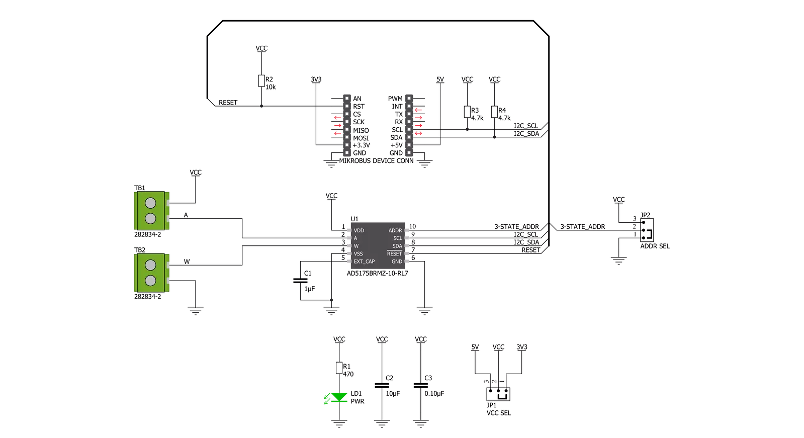
DIGI POT 7 Click is based on the AD5175, a single-channel 1024-position digital rheostat, with less than ±1% end-to-end resistor tolerance error and a 50-time programmable (50-TP) wiper memory from Analog Devices. It possesses one RDAC register that determines the resistor Wiper position and acts as a scratchpad register allowing unlimited resistance settings. The RDAC register can be programmed with any position set using the serial interface. When a desirable Wiper position is found, this value can be stored in a 50-TP memory register. Besides, the Wiper position is always restored to that position for subsequent Power-Up. The storing of 50-TP data takes approximately 350 ms, and during this time, the AD5175 is locked and doesn't acknowledge any new command preventing any changes from taking place. The nominal resistance between terminal W and terminal A is 10kΩ with 1024-tap
points accessed by the Wiper terminal, while in the Zero-Scale condition, a total Wiper resistance of 120Ω is present. The 10-bit data inside the RDAC register is decoded to select one of the 1024 possible Wiper settings. The AD5175 also provides the possibility of the Shutdown feature by executing the software shutdown command. This feature places the RDAC register in a Zero-Power-Consumption state where terminal A is disconnected from the Wiper terminal. The AD5175 can be removed from Shutdown Mode by executing Software Shutdown Command or performing the Hardware Reset feature. DIGI POT 7 click communicates with MCU using the standard I2C 2-Wire interface, with a clock frequency up to 100kHz in the Standard and 400kHz in the Fast Mode. Besides, it also allows the choice of the least significant bit (LSB) of its I2C slave address by positioning the SMD jumper
labeled as ADDR SEL to an appropriate position marked as 0 and 1. This Click board™ can be reset via software by calling the Reset command that loads the RDAC register with the contents of the most recently programmed 50-TP memory location. This register loads with mid-scale if no 50-TP memory location has been previously programmed. It also can be reset through the Hardware Reset pin, labeled as RST on the mikroBUS™ socket, by putting this pin in a logic low state. This Click board™ can operate with either 3.3V or 5V logic voltage levels selected via the VCC SEL jumper. This way, both 3.3V and 5V capable MCUs can use the communication lines properly. Also, this Click board™ comes equipped with a library containing easy-to-use functions and an example code that can be used, as a reference, for further development.

Features overview
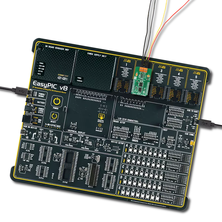
Development board
Nucleo 32 with STM32F031K6 MCU board provides an affordable and flexible platform for experimenting with STM32 microcontrollers in 32-pin packages. Featuring Arduino™ Nano connectivity, it allows easy expansion with specialized shields, while being mbed-enabled for seamless integration with online resources. The
board includes an on-board ST-LINK/V2-1 debugger/programmer, supporting USB reenumeration with three interfaces: Virtual Com port, mass storage, and debug port. It offers a flexible power supply through either USB VBUS or an external source. Additionally, it includes three LEDs (LD1 for USB communication, LD2 for power,
and LD3 as a user LED) and a reset push button. The STM32 Nucleo-32 board is supported by various Integrated Development Environments (IDEs) such as IAR™, Keil®, and GCC-based IDEs like AC6 SW4STM32, making it a versatile tool for developers.

Microcontroller Overview
MCU Card / MCU

Architecture
ARM Cortex-M0
MCU Memory (KB)
32
Silicon Vendor
STMicroelectronics
Pin count
32
RAM (Bytes)
4096
You complete me!
Accessories
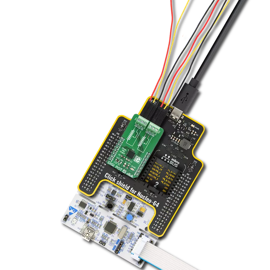
Click Shield for Nucleo-32 is the perfect way to expand your development board's functionalities with STM32 Nucleo-32 pinout. The Click Shield for Nucleo-32 provides two mikroBUS™ sockets to add any functionality from our ever-growing range of Click boards™. We are fully stocked with everything, from sensors and WiFi transceivers to motor control and audio amplifiers. The Click Shield for Nucleo-32 is compatible with the STM32 Nucleo-32 board, providing an affordable and flexible way for users to try out new ideas and quickly create prototypes with any STM32 microcontrollers, choosing from the various combinations of performance, power consumption, and features. The STM32 Nucleo-32 boards do not require any separate probe as they integrate the ST-LINK/V2-1 debugger/programmer and come with the STM32 comprehensive software HAL library and various packaged software examples. This development platform provides users with an effortless and common way to combine the STM32 Nucleo-32 footprint compatible board with their favorite Click boards™ in their upcoming projects.

Used MCU Pins
mikroBUS™ mapper
Take a closer look
Click board™ Schematic
Step by step
Project assembly

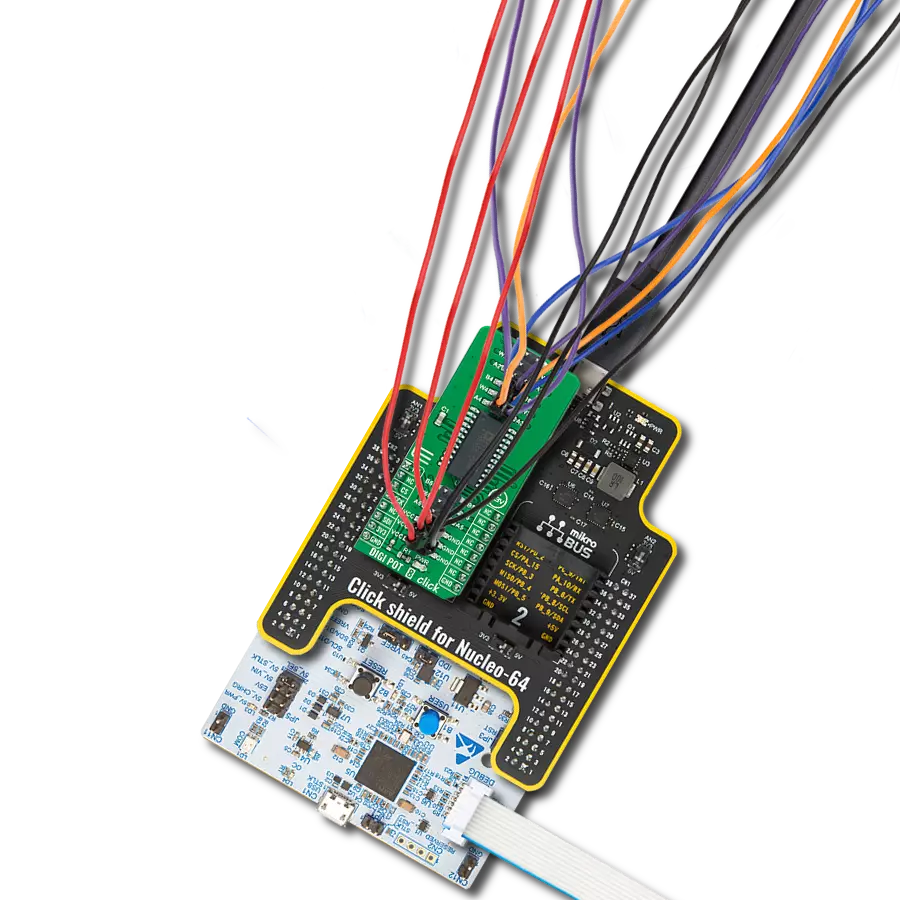
Start by selecting your development board and Click board™. Begin with the Nucleo 32 with STM32F031K6 MCU as your development board.


Software Support
Library Description
This library contains API for DIGI POT 7 Click driver.
Key functions:
digipot7_hw_reset- Hardware reset functiondigipot7_read_rdac- The function read a 10-bit RDAC datadigipot7_write_rdac- The function writes a 10-bit RDAC data
Open Source
Code example
The complete application code and a ready-to-use project are available through the NECTO Studio Package Manager for direct installation in the NECTO Studio. The application code can also be found on the MIKROE GitHub account.
/*!
 * @file main.c
 * @brief DIGIPOT7 Click example
 *
 * # Description
 * This is an example that demonstrate the use of the DIGI POT 7 Click board.
 *
 * The demo application is composed of two sections :
 *
 * ## Application Init
 * Initialization enables I2C, perform a hardware reset, enable write and set to normal operating mode,
 * also write log.
 *
 * ## Application Task
 * In this example we set different resistance values:
 * 1.024 kOhm, 2.048 kOhm, 4.096 kOhm and 8.192 kOhm.
 * Results are being sent to the Usart Terminal where you can track their changes.
 * All data logs write on USB uart changes approximately for every 5 sec.
 *
 * @author Stefan Ilic
 *
 */

#include "board.h"
#include "log.h"
#include "digipot7.h"

static digipot7_t digipot7;
static log_t logger;

void application_init ( void ) {
    log_cfg_t log_cfg;  /**< Logger config object. */
    digipot7_cfg_t digipot7_cfg;  /**< Click config object. */

    /**
     * Logger initialization.
     * Default baud rate: 115200
     * Default log level: LOG_LEVEL_DEBUG
     * @note If USB_UART_RX and USB_UART_TX
     * are defined as HAL_PIN_NC, you will
     * need to define them manually for log to work.
     * See @b LOG_MAP_USB_UART macro definition for detailed explanation.
     */
    LOG_MAP_USB_UART( log_cfg );
    log_init( &logger, &log_cfg );
    log_info( &logger, " Application Init " );

    // Click initialization.
    digipot7_cfg_setup( &digipot7_cfg );
    DIGIPOT7_MAP_MIKROBUS( digipot7_cfg, MIKROBUS_1 );
    err_t init_flag = digipot7_init( &digipot7, &digipot7_cfg );
    if ( I2C_MASTER_ERROR == init_flag ) {
        log_error( &logger, " Application Init Error. " );
        log_info( &logger, " Please, run program again... " );

        for ( ; ; );
    }
    log_printf( &logger, "----------------------------\r\n" );
    log_printf( &logger, " Hardware Reset \r\n" );
    digipot7_hw_reset( &digipot7 );
    Delay_ms ( 100 );

    log_printf( &logger, "----------------------------\r\n" );
    log_printf( &logger, " Enable Write \r\n" );
    digipot7_enable_write( &digipot7 );
    Delay_ms ( 100 );

    log_printf( &logger, "----------------------------\r\n" );
    log_printf( &logger, " Set normal operating mode \r\n" );
    digipot7_operating_mode( &digipot7, DIGIPOT7_NORMAL_MODE );
    Delay_ms ( 100 );

    log_printf( &logger, "----------------------------\r\n" );
    log_info( &logger, " Application Task " );
    log_printf( &logger, "----------------------------\r\n" );
}

void application_task ( void ) {
    log_printf( &logger, " Set Resistance: 1.024 kOhm \r\n" );
    log_printf( &logger, "----------------------------\r\n" );
    digipot7_set_resistance( &digipot7, 1024 );
    Delay_ms ( 1000 );
    Delay_ms ( 1000 );
    Delay_ms ( 1000 );
    Delay_ms ( 1000 );
    Delay_ms ( 1000 );

    log_printf( &logger, " Set Resistance: 2.048 kOhm \r\n" );
    log_printf( &logger, "----------------------------\r\n" );
    digipot7_set_resistance( &digipot7, 2048 );
    Delay_ms ( 1000 );
    Delay_ms ( 1000 );
    Delay_ms ( 1000 );
    Delay_ms ( 1000 );
    Delay_ms ( 1000 );

    log_printf( &logger, " Set Resistance: 4.096 kOhm \r\n" );
    log_printf( &logger, "----------------------------\r\n" );
    digipot7_set_resistance( &digipot7, 4096 );
    Delay_ms ( 1000 );
    Delay_ms ( 1000 );
    Delay_ms ( 1000 );
    Delay_ms ( 1000 );
    Delay_ms ( 1000 );

    log_printf( &logger, " Set Resistance: 8.192 kOhm \r\n" );
    log_printf( &logger, "----------------------------\r\n" );
    digipot7_set_resistance( &digipot7, 8192 );
    Delay_ms ( 1000 );
    Delay_ms ( 1000 );
    Delay_ms ( 1000 );
    Delay_ms ( 1000 );
    Delay_ms ( 1000 );
}

int main ( void )
{
    /* Do not remove this line or clock might not be set correctly. */
    #ifdef PREINIT_SUPPORTED
    preinit();
    #endif

    application_init( );

    for ( ; ; )
    {
        application_task( );
    }

    return 0;
}

// ------------------------------------------------------------------------ END
Additional Support
Resources
Category:Digital potentiometer